Article

Deep Learning-Assisted Index Estimator for Generalized LED Index Modulation OFDM in Visible Light Communication

Department of Electrical, Electronic and Computer Engineering, University of Ulsan, Ulsan 44610, Korea
*
Author to whom correspondence should be addressed.
These authors contributed equally to this work.
Photonics 2021, 8(5), 168; https://doi.org/10.3390/photonics8050168
Submission received: 1 April 2021 / Revised: 16 May 2021 / Accepted: 17 May 2021 / Published: 19 May 2021
(This article belongs to the Special Issue Visible Light Communication (VLC))

Abstract

:
In this letter, we present the first attempt of active light-emitting diode (LED) indexes estimating for the generalized LED index modulation optical orthogonal frequency-division multiplexing (GLIM-OFDM) in visible light communication (VLC) system by using deep learning (DL). Instead of directly estimating the transmitted binary bit sequence with DL, the active LEDs at the transmitter are estimated to maintain acceptable complexity and improve the performance gain compared with those of previously proposed receivers. Particularly, a novel DL-based estimator termed index estimator-based deep neural network (IE-DNN) is proposed, which can employ three different DNN structures with fully connected layers (FCL) or convolution layers (CL) to recover the indexes of active LEDs in a GLIM-OFDM system. By using the received signal dataset generated in simulations, the IE-DNN is first trained offline to minimize the index error rate (IER); subsequently, the trained model is deployed for the active LED index estimation and signal demodulation of the GLIM-OFDM system. The simulation results show that the IE-DNN significantly improves the IER and bit error rate (BER) compared with those of conventional detectors with acceptable run time.

1. Introduction

Visible light communication (VLC) is a promising alternative for complementing the overcrowded radio frequency bandwidth of wireless communication owing to its license-free operations, relative low cost, high spatial diversity, high bandwidth efficiency, and electromagnetic interference-free transmission [1,2,3,4,5,6,7]. Orthogonal frequency division multiplexing (OFDM) has been extensively used in VLC to maintain a better transmission rate due to its high spectral efficiency and low-complexity implementation to achieve better transmission rates [8,9]. Recently, the combination of multiple-input multiple-output (MIMO) and index modulation [10,11,12,13] to convey additional bits has gained a lot of attention in VLC literature. There are several published papers that investigated different aspects of the index modulation technique, such as non-coherent detection [14], low complexity detection [15], or precoding [16]. In addition, index modulation was proposed in optical communication [17] and later in [18] to implement generalized 4 × 4 light-emitting diode (LED) index modulation (GLIM-OFDM); in which the four transmitter side LEDs were divided into groups to transmit real-imaginary and positive-negative signals separately. As a result, depending on every OFDM symbol, just one LED in each group was chosen to convey the OFDM symbol parts. In [19], an LED selection algorithm for GLIM-OFDM was introduced to determine the best active LED combination to improve the system performance.
In general, a maximum likelihood (ML) detector is cost-ineffective and unpractical for an OFDM-based communication system. According to [18,19], maximum a posteriori (MAP) detectors are better than zero-forcing (ZF) and minimum mean square error (MMSE) detectors because of their better bit error rate (BER) performance and reasonable demodulation complexity. However, because all previously mentioned detectors only consider the instantaneous signal received at the receiver, the underlying relationship between the generated OFDM symbols is not fully exploited in the demodulation process.
Deep learning (DL) has had an enormous impact on various research fields over the last couple of years; it has been applied in wireless communication since then [20,21,22,23]. Many researchers have already suggested DL solutions to wireless communication problems, e.g., modulation detection and signal detection [24]. VLC channel models, similar to radio frequency channel models, have been developed according to probability and signal processing theories. Furthermore, DL techniques have recently made a number of advancements in the VLC system. Since the VLC transmission must be able to support a variety of constraints, such as dimming and lighting, according to user preferences in practical applications, the implementation of DL becomes more challenging. In [25], a data-driven approach based on DL was proposed to predict the outage events in a line-of-sight link. In [23], DL-based constellation design scheme for MIMO-VLC systems was introduced, which can significantly reduce complexity compared to existing schemes while maintaining a near-optimal performance. Despite a wide range of promising applications, the performance of VLC systems has been impaired by the high SNR required to achieve a low error rate for a variety of scenarios. Therefore, DL approach can be applied to VLC systems to improve performances in practical high-speed and low error-rate indoor transmission application, such as hospital facility. To the best of the authors’ knowledge, no researcher has used DL to improve the BER performance of the GLIM-OFDM system.
In this paper, a deep neural network (DNN)-aided active LED index estimator (IE) for improving the GLIM-OFDM detector performance in the VLC system is proposed. Unlike traditional DNN-based detectors, which directly estimate the transmitted bits at the transmitter side, the proposed method extracts the feature of the active LED index set with the time-domain signal of the receiver. Estimating the GLIM system’s active LED indexes is crucial for detecting the transmitted signal; this step has usually been performed by the ZF, MMSE, and MAP detectors in previous studies [18,19]. Although an ML-based detector is performance-optimal but impractical, a DNN-based solution is complexity-efficient and still useful for performance enhancement. Briefly, the key contributions of the proposed method are as follows:
  • An IE-based DNN (IE-DNN) is introduced into the GLIM (multiple-input multiple-output) MIMO-VLC demodulator;
  • Only a single IE-DNN module without the need to change the transmitter and the signal demodulation part in the receiver structure;
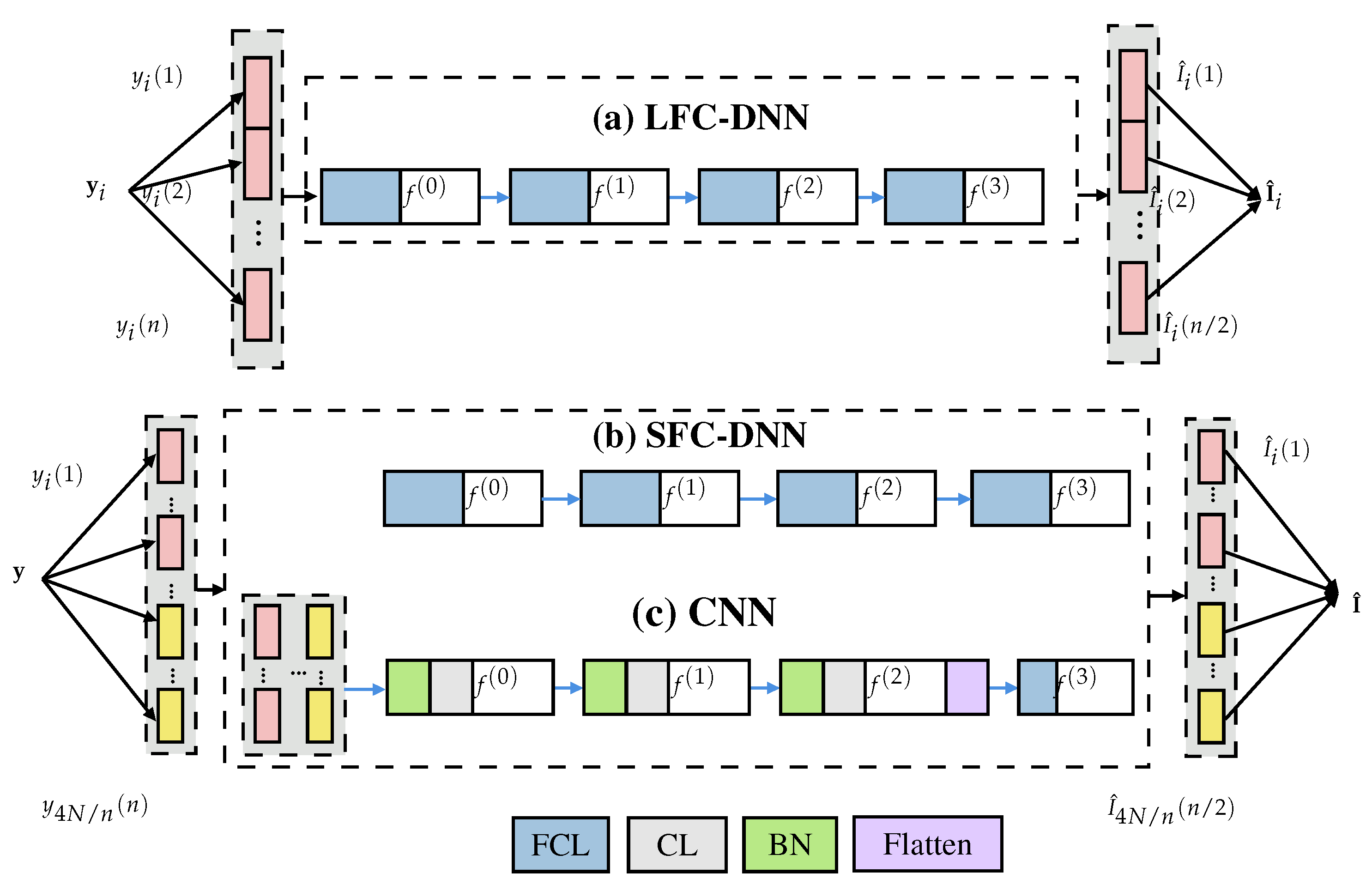
  • Three different structures of the IE-DNN are proposed and compared to demonstrate that the CNN-based estimator delivers the best performance;
  • In comparison with conventional detectors, a remarkable active LED index estimation accuracy significantly improves the BER performance at acceptable complexity costs.
This paper is organized as the following. In Section 2, we describe the system model of the GLIM with the mention of conventional detection techniques. In Section 3, we present the proposed DL-based index estimator include different network structures, the sample generation, and training specification stages. In Section 4, we provide the simulation results to demonstrate the advantage of the proposed index estimator in comparison with the previous ones. Finally, we provide the concluding remark in Section 5.

2. GLIM System Model

This section presents the GLIM system model in Figure 1, which focuses on the MIMO transmission of n T × n R ; n T are n R are the numbers of LEDs and PDs, respectively. Without loss of generality, it can be assumed that n T = n R = n , where n is an even number. In the GLIM, the OFDM modulator directly processes the complex frequency-domain OFDM frame through inverse fast Fourier transform (IFFT) operation. After the parallel-to-serial (P/S) operation, the time-domain OFDM signals x l ( l = 1 , , N ) are separated into their real and imaginary parts ( x l = x l , R + j x l , I ) and converted into the time-domain signal vector t = x 1 , R , x 1 , I , x 2 , R , x 2 , I , , x N , R , x N , I of length 2 N . Therefore, the GLIM technique transmission can help to convey complex and bipolar signal to the real and unipolar signal to be transmitted through the VLC channel. Consequently, the vector z = [ z 1 z n ] T is the signal transmitted by the LEDs. In the receiver side, after estimating the active LEDs and recovering the transmitted signal, the serial-to-parallel (S/P) and fast Fourier transform (FFT) operations convert the received signal to the estimated symbol. More specifically, N is the number of subcarriers and 4 N is divisible by n; consequently, the vector t is transformed into a matrix T of size 4 N / n × n / 2 . At each time instant i, each column of T (a signal vector of length n / 2 ) ) is transmitted by all n LEDs as z i . More specifically, let
s g n ( a ) = 1 , if a 0 1 , if a < 0 ,
the j-th signal of the i-th column of T can be transmitted with all n LEDs as
z i 2 j 1 + 1 = s g n ( T i , j ) + 1 2 T i , j , z i 2 j = s g n ( T i , j ) 1 2 T i , j .
Consequently, by activating a half number of LEDs while the other half are inactive, the signal z i is transmitted over the n × n optical MIMO channel as
y i = Hz i + n i ,
where y i = [ y i 1 , , y i n ] is the received signal, H R n × n is the optical communication channel matrix, and n i is real-valued additive white Gaussian noise with elements distributed as N ( 0 , σ w 2 ) . In addition, a flat fading channel is considered in this letter [18].
Among the three detection techniques, e.g., ZF, MMSE, and MAP, MAP is regarded as the preferred receiver as it can achieve the best BER performance [18]. Moreover, the number of transmitted signals ( 4 N ) is generally high owing to a large number of subcarriers ( N ) used for transmission. For example, in the OFDM modulation of eight subcarriers, the transmitted signal vector at the LEDs has a size of 32 and this number is 128 with 32 subcarriers. Meanwhile, a small number of LEDs in MIMO-VLC systems, usually four LEDs [18], or eight LEDs [19], are used in transmission, leads to only four or eight signals that are simultaneously transmitted by LEDs and detected by the MAP detectors at the same time. To improve the demodulation performance, all the received signals (e.g., the vector y = y 1 , y i , y 4 N / n ) instead of only the n-length received signals y i should be simultaneously considered in the demodulation process. In the next section, three model-driven DNN architectures as alternatives to conventional receivers (e.g., ZF, MMSE, and MAP detectors) are proposed; the methods combine DNN with expert knowledge for wireless communication.

3. Structure and Operation of DL-Based Index Estimator

3.1. Proposed DL-Based Index Estimator

To consider the BER and computational complexity of different network structures and parameters for the active LED IE, three IE-DNN structures are considered. The three IE-DNN structures are constructed with an LED-based fully connected DNN (LFC-DNN), a subcarrier-based fully connected DNN (SFC-DNN), and a convolutional neural network (CNN), respectively. The DNNs contain several sub-blocks that are sequentially connected (the so-called hidden layers). The three IE-DNNs are presented in Figure 2.
More specifically, for a 4 × 4 system and OFDM symbols with 16 subcarriers, the size of the time-domain signal vector t is 32 because the real and imaginary parts are transmitted separately. Thus, for the LFC-DNN in Figure 2, the input is a vector of length four, and the output is a vector of length two. For the SFC-DNN and CNN, the outputs are vectors of length 16; the inputs are vectors of length 64 and matrices of size 16 × 4 , respectively.

3.1.1. LFC-DNN

The LFC-DNN takes the instantaneous received signal at the PDs ( y i ) as the input. The predicted instantaneous active LED index vector for the corresponding input is obtained as a vector of length n / 2 at the output. For a 4 × 4 system, the received signal vector of length four ( y i ) is taken as the DNN network input. Subsequently, the LFC-DNN outputs a vector of length two as the estimated LED index value, for example, I ˜ i = I ˜ i 1 I ˜ i 2 T with I ˜ 1 i as the estimated active index for the T i , 1 signal. The estimated active index I ^ i can be derived with hard decision decoding as
I ^ i j = 1 , I ˜ i j 0.5 0 , I ˜ i j < 0.5 ,
If I ^ i 1 = 1 , the signal T i , 1 has a positive value and was transmitted by the first LED. If I ^ i 1 = 0 , the signal T i , 1 has a negative value and was transmitted by the second LED. For i = 1 , , 4 N / n , the estimated active index vectors I ^ i are concatenated to determine the estimated vector I ^ = I ^ 1 , I ^ i , I ^ 4 N / n . Finally, with the estimated active LED indexes, the demodulation process is generally conducted with FFT and QAM demodulation steps to obtain the original binary information sequence, similar to the previous demodulator [18]. All four sub-blocks are composed of fully connected layers (FCLs) and activation functions f 0 , , f 3 . The numbers of neurons in the FCLs are 32, 16, 16, and 2, respectively. Moreover, the activation functions for the first three sub-blocks f 0 , f 1 , f 2 are “ReLU” activation functions, while the activation function for the last sub-block f 3 is a “Sigmoid” activation function. The “ReLU” function is as following form
ReLU ( x ) = x , x 0 0 , x < 0 ,
while the “Sigmoid” function has the following form
S ( x ) = 1 1 + e x .

3.1.2. SFC-DNN

Because the time-domain signal t after the IFFT step is a vector that the elements contain underlying information about the relationship between the QAM symbols mapped onto the OFDM subcarriers, the input for the network should be the entire received time-domain signal vector y = [ y 1 y 4 N / n ] to exploit the underlying features of the time-domain generated signals. Intuitively, a structure that uses the received signal vector y at once is more complex and requires higher computational complexity cost. Nevertheless, it will be demonstrated in the simulation section that this cost will be accommodated by the performance gains, which is of most importance since the computational capacity of recent mobile devices has been enormously enlarged. The SFC-DNN is identical to the LFC-DNN, except that the input of the network is the vector y , which is composed of all time-domain received signal at all LEDs (it is a vector of length 4 N ) . To facilitate the increase in the number of inputs, the numbers of neurons in the FCLs are 48, 32, 32, and 16, respectively. The remaining parameters (e.g., the activation functions) are identical to those of the proposed LFC-DNN.

3.1.3. CNN

The CNN structure contains four sub-blocks, such as the previously presented DNN structures. However, instead of using the FCL in all sub-blocks, a batch normalization (BN), convolution layer (CL), and an activation function are employed in the first three sub-blocks while the last sub-block remains identical to those of the previously proposed structures. The CL contains 16 kernels with sizes of 1; the number of neurons in the last FCL is 16. Such as the SFC-DNN structure, the CNN structure receives the received time-domain signal [ y 1 , , y 4 N / n ] T as the network input in the form of a matrix to exploit the underlying features of the received signals. It is well known that the CL can perform neighborhood filtering on the inputs to capture the input features [26]. Moreover, to ensure that the inputs in the consecutive layer follow the same distribution, to improve the speed of CNN training significantly, and to alleviate the initial parameter dependency of the learning process, BN is considered before using the CL in each sub-block.

3.2. Sample Generation

Training samples are obtained by randomly generating information bits and processing according to the system model as QAM mapping, IFFT. Then, the cyclic prefix (CP) is added to IFFT symbols to effectively mitigate multipath which induces intersymbol interference. Subsequently, the time-domain OFDM symbols are mapped onto the corresponding active and inactive LEDs; for each signal, a positive value indicates that the index value is one and vice versa. More specifically, one training sample can be denoted as u = y , I . It should be mentioned that due to the difference between the proposed networks, the sizes of input vectors are different. However, a similar process of training and testing sample set generation can be applied. Moreover, to speed up the training process and improve the prediction performance, we usually notice that a small number of layers will outperform the more complicated network when the i-th element of l-th normalization training sample d i l [23] is expressed as
d i l = u i ( l ) E u i max u i min u i .

3.3. Training Specification

The proposed IE-DNN estimators need to be trained offline prior to the online deployment stage. The parameters of the IE-DNN network are optimized during offline training. The binary cross-entropy loss function [26] is used to quantify the difference between the predicted and actual training indexes as
L I , I ^ = τ = 1 N I τ log I ^ τ + 1 I τ log 1 I ^ τ N ,
where N = n / 2 for the LFC-DNN network and N = 4 N / n for the SFC-DNN and CNN networks, respectively. In the next step, the network parameters can be optimized with the adaptive moment estimation optimizer (ADAM), with early termination and ReduceLROnPlateau callbacks in Keras. More specifically, ADAM [27] is an algorithm based on adaptive estimates of lower-order moments to first-order gradient-based optimize stochastic objective function. After offline training, the optimal parameters for the IE-DNN estimator can be used to estimate the active LED index at the receiver side. If the received time-domain OFDM symbols are input into the trained IE-DNN estimator, the active LED index can be estimated in accordance with the framework defined in Section 2. With the estimated active LED indexes, the demodulation is similar to that of the conventional demodulators [18].

3.4. Complexity Analysis

The computational complexity is generally measured by the number of operations based on the active LED index detector and the OFDM algorithm [18]. The required number of FLOPs operations of the algebraic expressions [28] can be summarized in Table 1. Moreover, the real operations for GLIM with MAP detector consist of 76 N + 4 N log 2 ( N ) real multiplications and 32 N + 4 log 2 ( N ) real additions, which can be approximated as O N log 2 N [18]. On the other hand, the computational complexity of the proposed active LED index detectors is dominated by the structure of the networks, such as the dimension of each input, output of layer, and the number of hidden layers. More specifically, the operations for the GLIM with SFC-DNN also consist of 98 N + 4 N log 2 ( N ) real multiplications and 64 N + 4 log 2 ( N ) real additions, while the operations for the GLIM with CNN can be composed of 80 N + 2 N 2 + 4 N log 2 ( N ) real multiplications and 48 N + N 2 + 4 log 2 ( N ) real additions. However, most of the network operations are the feed-forward computations with sparse vector-matrix and matrix-matrix multiplications. Therefore, the asymptotic complexity for the proposed SFC-DNN and CNN detectors can be similarly expressed as O N log 2 N and O N 2 , respectively.

4. Results and Discussion

In this section, the estimation accuracy of the active LED indexes is evaluated with the index error rate (IER), and the BER characteristics of the proposed methods (LFC-DNN, SFC-DNN, and CNN) are compared with those of the conventional index estimation algorithms (the best method is MAP detection). Besides, the complexity costs are also compared in terms of the run time measurement. More specifically, a MIMO VLC system’s performance composed of 4 LEDs and 4 PDs are shown. For convenience, the system configurations of the simulation are similar to those in [18]: a 5 m × 5 m × 3 m room, positions of LEDs, PDs, and the channel gain matrix are similar to the physical channel C in [18] is used for the simulation. At the transmitter, OFDM is employed with two cases. Case 1 and 2 have N = 8 and N = 32 subcarriers, respectively. In both cases, 4-QAM symbols are mapped onto the subcarrier before the IFFT. A CP length of six is chosen for the computer simulation to ensure that it covers the maximal delay spread of the channel.
Subsequently, the IE-DNNs are trained over 200 iterations with a batch size of 400 samples. Moreover, the networks are trained with 200 epochs during each iteration. When the validation loss value stops improving, the iteration can be terminated early. When the validation loss does not improve after 50 epochs, the learning rate is reduced by 1/3 until it reaches the minimum (0.0002).
Figure 3 compares the index error rates (IER) of the different algorithms. Nevertheless, the MAP estimator only achieves an IER below 0.1 while the proposed SFC-DNN and CNN are better in estimating the active LED index. More specifically, an accuracy of 0.001 can be obtained in the high SNR regime. In addition, the higher the number of subcarriers is, the better the index accuracy is. Because the LFC-DNN and MAP detection have similar results, the simultaneous extraction of all received signals at the PDs and the additional signal features remarkably improve the index estimation accuracy.
Figure 4 presents the BERs of Case 1. As the IER values of the MAP detection and LFC-DNN are similar, their BERs are the worst among those of all compared estimators. The CNN-based estimator exhibits significantly better BERs than the others. More specifically, at the SNR value of 10 dB, the proposed CNN, FCN, and the conventional MAP detector achieve a BER value of 10 4 , 10 3 , and 10 2 , respectively. Nevertheless, the SNR gain in the BER is only 4 dB when a CNN instead of MAP detection is used. This is because the total number of correctly estimated active LED indexes is not the sole dominant factor that affects the BERs of the demodulator. Because the estimator only estimates the active LED index, after the CNN-based and other estimators, the signal magnitude of the active LEDs is also an essential factor that impacts the BER. With its lower IER, MAP detection can estimate a good number of active LEDs with large signal magnitudes, which leads to an acceptable BER. Moreover, owing to the remarkably high accuracy of SFC-DNN and CNN regarding the IER, the additional correct LED index estimation usually lower in signal magnitude and not as important as the higher ones. Therefore, only an SNR gain of 4 dB can be achieved with the CNN-based estimator. On the other hand, with lower complexity cost, the proposed FCN can only provide a SNR gain of 3 dB at the BER value of 10 6 .
The same observation is made in Case 2. In Figure 5, the CNN-based estimator achieves an SNR gain of approximately 3 dB, and SFC-DNN achieves an SNR gain of only 2 dB. More specifically, the proposed PCN provides a same performance with the conventional MAP detector in almost all SNR regions, except the SNR value between 0 and 5 dB. Additionally, in comparison with Case 1, due to a large number of employed subcarriers, an additional SNR increment of around 3 dB is required to maintain same value of 10 6 BER. Therefore, the performance observed in all figures demonstrates the advantage of the proposed detector over the conventional MAP detector in terms of error rate performance, which is most important to the reliability of VLC systems.
In Table 2, the complexity costs of the compared estimators are analyzed. To evaluate the run time of both IE-DNN estimators and the MAP estimator, we use MATLAB to convert the trained model from Keras and estimate the run time for each sample. It should be noted that only the active LED index estimation results are evaluated in this simulation because all other operations (e.g., the costly IFFT computation) are the whole part and identical for all estimators. For all cases, the run time increases with the number of subcarriers hence the number of trainable parameters. The MAP estimator with its simple algorithm and poorer performance has the shortest estimation time; by contrast, the SFC-DNN with the highest number of trainable parameters has the longest estimation time. Interestingly, the CNN exhibits the best performance. At first glance, it seems that the SFC-DNN and CNN estimators are computational costly for GLIM-VLC systems. However, compared with other operations, such as IFFT and QAM demodulation (which significantly increase complexity), the active LED index estimation increase does not significantly impact the total complexity cost. Moreover, with the ever-growing computational power of mobile devices and required quality of services, the BER improvement is much more important than complexity costs.

5. Conclusions

This paper presents an IE-DNN for active LED index estimation in GLIM-MIMO-VLC demodulation. The proposed network structure promotes signal demodulation by estimating the correct active LED indexes. Moreover, the simulation results of the proposed LFC-DNN, SFC-DNN, and CNN are compared. According to the results, the relationship between the time-domain OFDM signals can be exploited to a higher extent with the IE-DNN structures. Especially, with an acceptable complexity cost, the network with CNN one is the one that can provide the best IER and BER performance improvement.

Author Contributions

All authors discussed the contents of the manuscript and contributed to its presentation. M.L.-T. designed and implemented the proposed scheme, analyzed the simulation results and wrote the paper under the supervision of S.K. All authors have read and agreed to the published version of the manuscript.

Funding

This work was supported by the 2021 Research Fund of University of Ulsan.

Institutional Review Board Statement

Not applicable.

Informed Consent Statement

Not applicable.

Data Availability Statement

Not applicable.

Conflicts of Interest

The authors declare no conflict of interest.

Abbreviations

The following abbreviations are used in this manuscript:
AWGNAdditive white Gaussian noise
CLConvolution layers
CNNConvolutional neural network
DNNDeep neural network
FCLFully connected layers
MIMOMultiple-input multiple-output
LEDLight emitting diode
GLIMGeneralized LED index modulation optical orthogonal frequency-division multiplexing
PDPhoto detector
MAPMaximum a posteriori
ZFZero-forcing
VLCVisible light communication

References

  1. Komine, T.; Nakagawa, M. Fundamental Analysis for Visible-Light Communication System Using LED Lights. IEEE Trans. Consum. Electron. 2004, 50, 100–107. [Google Scholar] [CrossRef]
  2. Matheus, L.E.M.; Vieira, A.B.; Vieira, L.F.M.; Vieira, M.A.M.; Gnawali, O. Visible Light Communication: Concepts, Applications and Challenges. IEEE Commun. Surv. Tutor. 2019, 21, 3204–3237. [Google Scholar] [CrossRef]
  3. Gong, C. Visible Light Communication and Positioning: Present and Future. Electronics 2019, 8, 788. [Google Scholar] [CrossRef] [Green Version]
  4. Le Tran, M.; Kim, S. Effective Receiver Design for MIMO Visible Light Communication with Quadrichromatic LEDs. Electronics 2019, 8, 1383. [Google Scholar] [CrossRef] [Green Version]
  5. Guo, J.N.; Zhang, J.; Xin, G.; Li, L. Constant Transmission Efficiency Dimming Control Scheme for VLC Systems. Photonics 2021, 8, 7. [Google Scholar] [CrossRef]
  6. Wang, Q.; Giustiniano, D.; Zuniga, M. In Light and in Darkness, in Motion and in Stillness: A Reliable and Adaptive Receiver for the Internet of Lights. IEEE J. Sel. Areas Commun. 2018, 36, 149–161. [Google Scholar] [CrossRef] [Green Version]
  7. Li, D.C.; Chen, C.C.; Liaw, S.K.; Afifah, S.; Sung, J.Y.; Yeh, C.H. Performance Evaluation of Underwater Wireless Optical Communication System by Varying the Environmental Parameters. Photonics 2021, 8, 74. [Google Scholar] [CrossRef]
  8. Armstrong, J. OFDM for Optical Communications. J. Light. Technol. 2009, 27, 189–204. [Google Scholar] [CrossRef]
  9. Pathak, P.H.; Feng, X.; Hu, P.; Mohapatra, P. Visible Light Communication, Networking, and Sensing: A Survey, Potential and Challenges. IEEE Commun. Surv. Tutor. 2015, 17, 2047–2077. [Google Scholar] [CrossRef]
  10. Basar, E.; Aygolu, U.; Panayirci, E.; Poor, H.V. Orthogonal Frequency Division Multiplexing With Index Modulation. IEEE Trans. Signal Process. 2013, 61, 5536–5549. [Google Scholar] [CrossRef]
  11. Basar, E. Reconfigurable Intelligent Surface-Based Index Modulation: A New Beyond MIMO Paradigm for 6G. IEEE Trans. Commun. 2020, 68, 3187–3196. [Google Scholar] [CrossRef] [Green Version]
  12. Mao, T.; Wang, Q.; Wang, Z.; Chen, S. Novel Index Modulation Techniques: A Survey. IEEE Commun. Surv. Tutor. 2018, 21, 1. [Google Scholar] [CrossRef] [Green Version]
  13. Ishikawa, N.; Sugiura, S.; Hanzo, L. 50 Years of Permutation, Spatial and Index Modulation: From Classic RF to Visible Light Communications and Data Storage. IEEE Commun. Surv. Tutor. 2018, 20, 1905–1938. [Google Scholar] [CrossRef] [Green Version]
  14. Fazeli, A.; Nguyen, H.H.; Hanif, M. Generalized OFDM-IM with Noncoherent Detection. IEEE Trans. Wirel. Commun. 2020, 4, 1323–1337. [Google Scholar] [CrossRef]
  15. Zheng, J.; Liu, Q. Low-Complexity Soft-Decision Detection of Coded OFDM with Index Modulation. IEEE Trans. Veh. Technol. 2018, 67, 7759–7763. [Google Scholar] [CrossRef]
  16. Belaoura, W.; Althunibat, S.; Qaraqe, K.A.; Ghanem, K. Precoded Index Modulation Based Multiple Access Scheme. IEEE Trans. Veh. Technol. 2020, 69, 12912–12920. [Google Scholar] [CrossRef]
  17. Mesleh, R.; Elgala, H.; Haas, H. Optical Spatial Modulation. J. Opt. Commun. Netw. 2011, 3, 234. [Google Scholar] [CrossRef]
  18. Yesilkaya, A.; Basar, E.; Miramirkhani, F.; Panayirci, E.; Uysal, M.; Haas, H. Optical MIMO-OFDM with Generalized LED Index Modulation. IEEE Trans. Commun. 2017, 65, 3429–3441. [Google Scholar] [CrossRef] [Green Version]
  19. Le Tran, M.; Kim, S.; Ketseoglou, T.; Ayanoglu, E. LED Selection and MAP Detection for Generalized LED Index Modulation. IEEE Photon. Technol. Lett. 2018, 30, 1695–1698. [Google Scholar] [CrossRef]
  20. Chen, M.; Challita, U.; Saad, W.; Yin, C.; Debbah, M. Artificial Neural Networks-Based Machine Learning for Wireless Networks: A Tutorial. IEEE Commun. Surv. Tutor. 2019, 21, 3039–3071. [Google Scholar] [CrossRef] [Green Version]
  21. Luong, T.V.; Ko, Y.; Vien, N.A.; Nguyen, D.H.N.; Matthaiou, M. Deep Learning-Based Detector for OFDM-IM. IEEE Wireless Commun. Lett. 2019, 8, 1159–1162. [Google Scholar] [CrossRef] [Green Version]
  22. Wang, J.; Jiang, C.; Zhang, H.; Ren, Y.; Chen, K.C.; Hanzo, L. Thirty Years of Machine Learning: The Road to Pareto-Optimal Wireless Networks. IEEE Commun. Surv. Tutor. 2020, 22, 1472–1514. [Google Scholar] [CrossRef] [Green Version]
  23. Le-Tran, M.; Kim, S. Deep Learning-Based Collaborative Constellation Design for Visible Light Communication. IEEE Commun. Lett. 2020, 24, 2522–2526. [Google Scholar] [CrossRef]
  24. Sun, L.; Wang, Y. CTBRNN: A Novel Deep-Learning Based Signal Sequence Detector for Communications Systems. IEEE Signal Process. Lett. 2019, 27, 21–25. [Google Scholar] [CrossRef]
  25. Wu, Z.Y.; Ismail, M.; Serpedin, E.; Wang, J. Efficient Prediction of Link Outage in Mobile Optical Wireless Communications. IEEE Trans. Wirel. Commun. 2020, 20, 882–896. [Google Scholar] [CrossRef]
  26. Goodfellow, I.; Bengio, Y.; Courville, A. Deep Learning Adaptive Computation and Machine Learning; The MIT Press: Cambridge, MA, USA, 2016. [Google Scholar]
  27. Kingma, D.P.; Ba, J. Adam: A Method for Stochastic Optimization. arXiv 2017, arXiv:cs/1412.6980. [Google Scholar]
  28. Golub, G.H.; Loan, C.F.V. Matrix Computations, 4th ed.; Johns Hopkins Studies in the Mathematical Sciences; Johns Hopkins University Press: Baltimore, MD, USA, 2012. [Google Scholar]
Figure 1. System model with proposed estimator.
Photonics 08 00168 g001
Figure 2. IE-DNN-assisted active LED IE structures for GLIM-MIMO system: (a) LFC-DNN, (b) SFC-DNN, (c) CNN.
Photonics 08 00168 g002
Figure 3. Comparison of IER: (a) Case 1 and (b) Case 2.
Photonics 08 00168 g003
Figure 4. Comparison of BERs for Case 1.
Photonics 08 00168 g004
Figure 5. Comparison of BERs for Case 2.
Photonics 08 00168 g005
Table 1. Complexity cost of matrix-vector operations [28].
ExpressionDescriptionMultiplicationsSummationsTotal Flops
α a Vector ScalingN N
α A Matrix Scaling M N M N
AbMatrix-Vector Prod. M N M ( N 1 ) 2 M N M
ABMatrix-Matrix Prod. M N L M L ( N 1 ) 2 M N L M L
ADMatrix-Diagonal Prod. M N M N
a H b Inner Prod.N N 1 2 N 1
ac H Outer Prod. M N M N
A H A Gram M N ( N + 1 ) 2 N ( M 1 ) ( N + 1 ) 2 M N 2 + N M N 2 N 2
A 2 Euclidean norm M N M N 1 2 M N 1
Q 1 Inverse of Pos. Definite N 3 2 + 3 N 2 2 N 3 2 N 2 2 N 3 + N 2 + N Including N roots
Table 2. Comparison of run time of active LED IEs.
DetectorNumbers of Trainable ParametersEstimation Time
   (Case 1/Case 2)(Case 1/Case 2)
LFC-DNN994/99413 ms/44 ms
SFC-DNN4736/954428 ms/78 ms
CNN3096/632822 ms/67 ms
MAP-/-6 ms/23 ms
Publisher’s Note: MDPI stays neutral with regard to jurisdictional claims in published maps and institutional affiliations.

