Article

Hybrid POF/VLC Links Based on a Single LED for Indoor Communications

Instituto de Telecomunicaciones y Aplicaciones Multimedia, ITEAM, Universitat Politècnica de València, Camino de Vera, 46022 Valencia, Spain
*
Author to whom correspondence should be addressed.
Photonics 2021, 8(7), 254; https://doi.org/10.3390/photonics8070254
Submission received: 25 May 2021 / Revised: 21 June 2021 / Accepted: 29 June 2021 / Published: 2 July 2021
(This article belongs to the Special Issue Visible Light Communication (VLC))

Abstract

:
A hybrid fiber/wireless link based on a single visible LED and free of opto-electronic intermediate conversion stages has been demonstrated for indoor communications. This paper shows the main guidelines for proper coupling in fiber/air/detector interfaces. Experimental demonstration has validated the design results with very good agreement between geometrical optics simulation and received optical power measurements. Different signal bandwidths and modulation formats, i.e., QPSK, 16-QAM, and 64-QAM, have been transmitted over 1.5 m polymer optical fiber (POF) and 1.5 m free-space optics (FSO). Throughputs up to 294 Mb/s using a 64-QAM signal have been demonstrated using a commercial LED, which paves the way for massive deployment in industrial applications.
Keywords:
POF; FSO; LiFi; LED

1. Introduction

Future smart factories in Industry 4.0 will require fast and reliable wireless connectivity to provide automation and real-time control of equipment [1]. Optical wireless communication (OWC) is a promising technology for enabling such industrial transformation [2,3] since it offers a huge amount of unregulated bandwidth, high security, low latency, and immunity to electromagnetic interference. However, OWC links are based on line-of-sight (LOS) signal reception, and therefore the blockage of direct transmission by shadowing or obstacles is its main disadvantage. Current OWC solutions utilize multiple-input multiple-out (MIMO) schemes where several transmitters and receivers are employed [4,5].
Among the OWC approaches, visible light communication (VLC) is an attractive choice for indoor networks because of its capability to combine lighting and communications while using low-cost narrow bandwidth light-emitting diodes (LEDs), also known as light-fidelity (Li-Fi) [6]. Recent works have demonstrated the feasibility of OFDM transmission with data rates of 15.7 Gbps, employing off-the-shelf LEDs [7]; allowing multiuser access, interference mitigation, and mobility support [8,9]; and enabling 100 Gbps LiFi access network [10] when laser-based lighting or micro-LEDs are considered.
Furthermore, recent works demonstrated the interest in heterogeneous networks based on hybrid polymer optical fiber (POF)/VLC links as a converged solution to integrate fiber backbone and in-building networks [11,12] where large core diameter and small bending radius of POFs lead to low cost and easy installation. These systems include a photodiode (PD) to provide opto-electrical conversion of the signal transmitted over the POF before supplying the recovered electrical signal to the VLC optical source, i.e., an LED as an illuminating source or a laser diode (LDs) if larger bandwidths and collimated beams are required.
Among different types of POFs, the 1-mm core size poly-methyl methacrylate (PMMA) step-index (SI)-POF is the most popular for indoor communications, whose major drawback is a low transmission bandwidth due to intermodal dispersion. However, in [13] a transmission rate of 14.77 Gb/s was demonstrated by using wavelength division multiplexed (WDM) signals emitted by several LDs. Moreover, bandwidth efficient advanced modulation formats, i.e., multilevel pulsed amplitude modulation (M-PAM) signals modulating a micro-LED, with larger bandwidth than conventional LEDs, allowed 5 Gb/s transmission over 10 m [14].
As an attractive simple high capacity indoor communication system, Correa et al. have recently proposed using large core optical fibers acting as the light source in a luminaire-free scheme for VLC transmission; 2 Gb/s was achieved using two WDM LDs over 1.6 m [15].
In this paper, we propose, for the first time to the authors’ knowledge, the use of low-cost centralized LEDs to feed the fiber network with no further opto-electrical conversions after the fiber section to wirelessly connect the user equipment. Hence, no light source is required for the VLC link; in this way, an optical network industrial infrastructure can be significantly simplified.
The paper is organized as follows: Section 2 describes the VLC solution over POF. Section 3 reports the experimental results of the single LED hybrid POF/VLC link. Finally, conclusions are presented in Section 4.

2. Description of a Single LED Hybrid POF/VLC Link

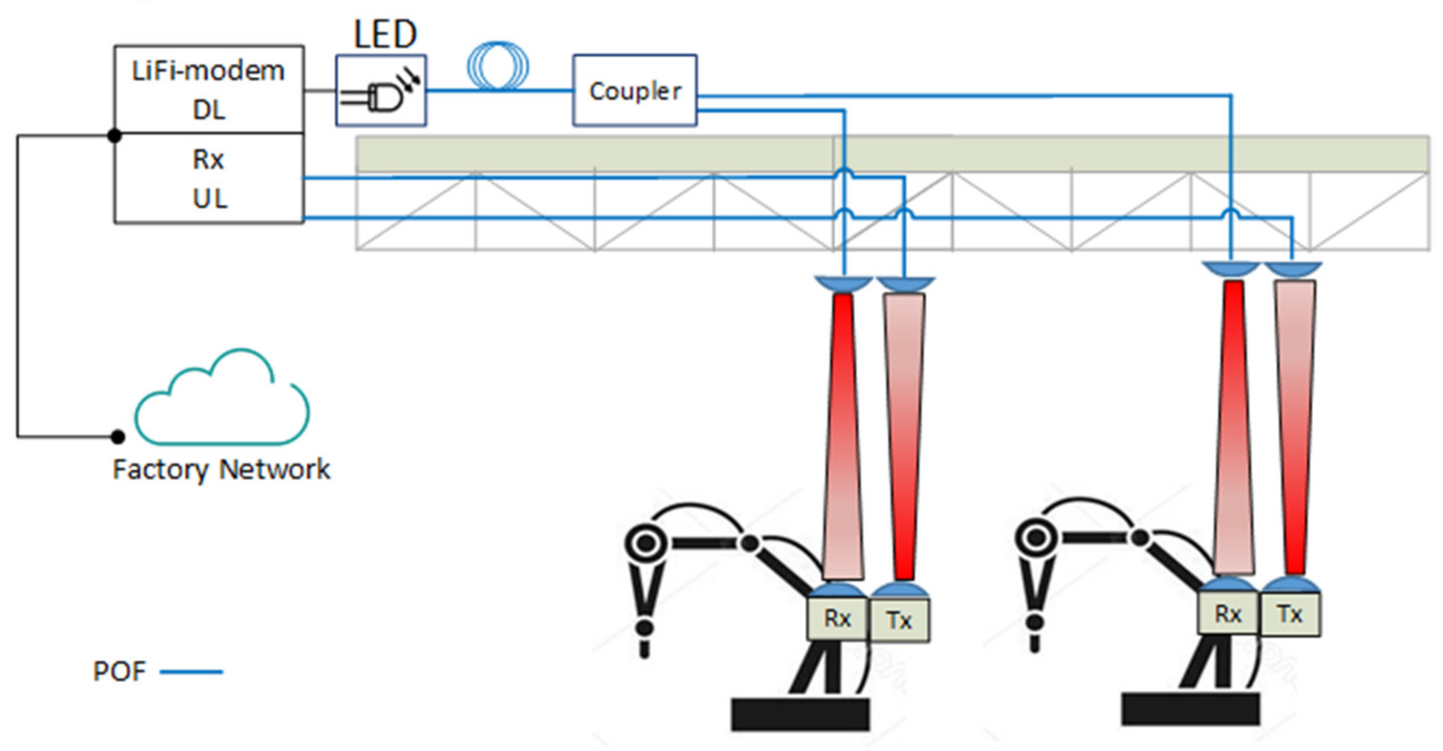
Figure 1 shows the proposal for Li-Fi wireless communication between a factory network and fixed arms of robots, i.e., users, where both uplink and downlink could employ VLC technology with POF cabling providing multiple signal access points. The network wireless infrastructure may consist of multiple distributed access points with no overlapping coverage despite the proximity between users. As a result, interference is avoided, and the spectrum can be reused efficiently. Moreover, MIMO techniques with diversity receiver designs [16] can be employed in advanced implementations in order to prevent link blockage.
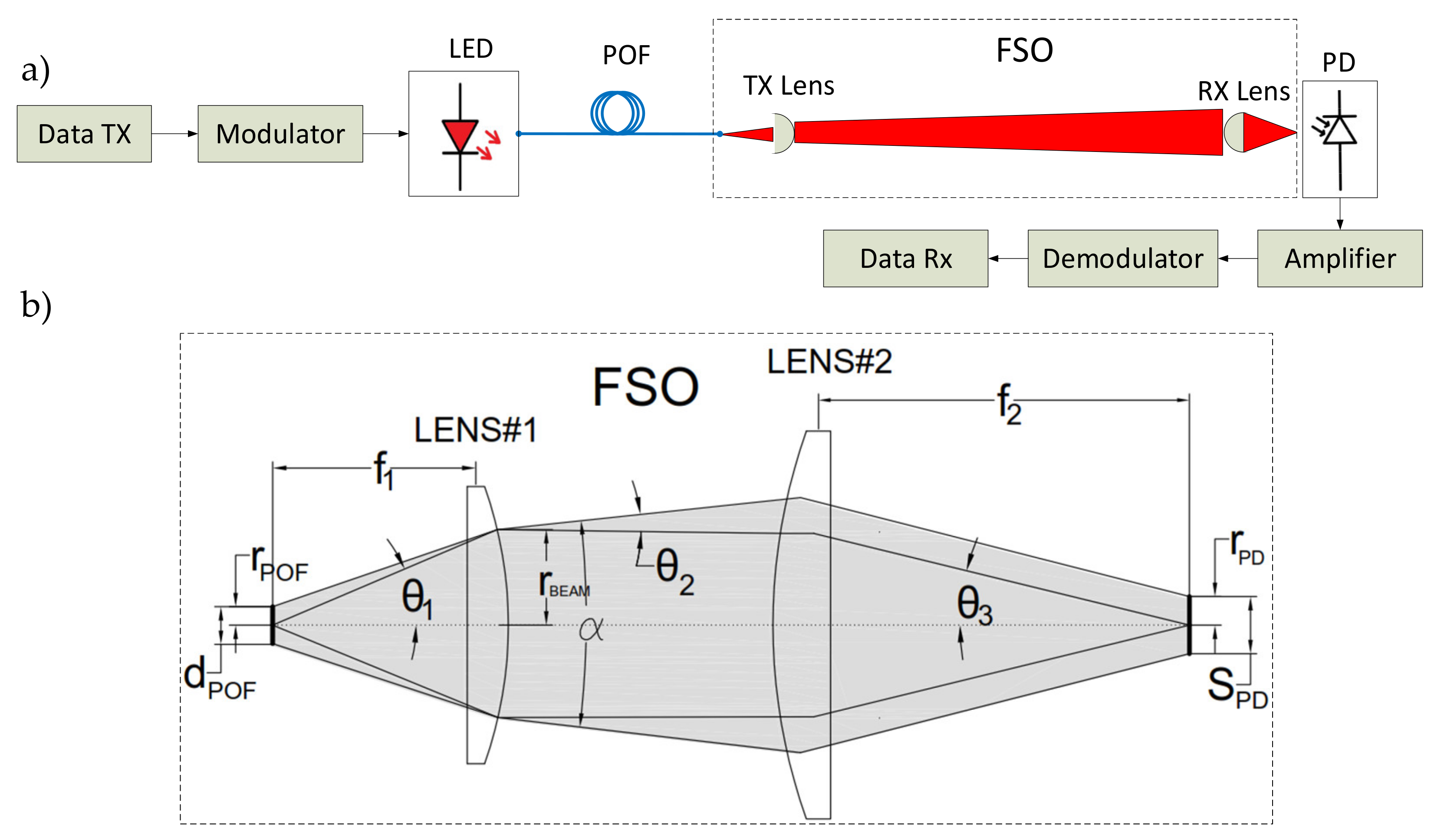
Therefore, a new hybrid POF/VLC link based on a single LED for indoor communications is proposed, as shown in Figure 2a. In this paper, we describe the implementation of a POF link as a front-haul downlink solution for feeding the LiFi system. The passive optical front-end at the ceiling only includes an optical lens with no optical-to-electric converter (O/E), i.e., optical source.
The transmitter consists of a low-cost commercial LED emitting light in the visible spectral range with directly modulated intensity. The output light is launched into the 1 mm diameter POF whose fiber-output is attached to a collimating lens to create the wireless interface. A lens is attached to the receiver input to focus the light onto a Ø1 mm photodetector. Then, a trans-impedance amplifier (TIA) is used as an amplification stage.
Collimators are often used to modify the divergent light emission from an optical fiber into a parallel light beam. Most commercial fiber optic collimators are designed for 125 μm diameter silica fibers with low numerical aperture (NA). However, an appropriate collimation system is essential to maximize the received optical power and ensure system operation. Moreover, a smaller collimator optic is preferred as it is cheaper to manufacture and requires less space for installation. Figure 2b shows the schematic of the free-space optics (FSO) link, including the geometrical optics and ray tracing, which are based on two lenses for proper light collimation as described below.
The purpose is to have efficient coupling (i.e., reduced insertion losses) and small collimator optics that minimizes cost. The numerical aperture provides the angle of acceptance of light from an optical system, i.e., the POF:
N A = n   s i n θ 1
where n is the refractive index of the propagation medium and θ 1 is the angle of light emission from the optical element.
The fiber core size has a significant effect on the divergence angle of the collimated output beam, θ 2 . Consider a nonpoint light source placed at the focal point of the lens, f 1 , where the fiber diameter gives the size of the optical source, d P O F = 2 · r P O F . Using the paraxial approximation, the divergence angle of the output beam at lens #1 can be calculated as follows:
θ 2 r a d = r P O F / f 1
and the resulting beam radius at the exit of lens #1 corresponds to:
r B E A M = θ 1 f 1
In general, POFs have a relatively large core size to be considered as a point source. Therefore, the collimated beam will not be of constant diameter but will expand slightly as it propagates according to a beam divergence given by α = 2 θ 2 . To reduce this divergence, lenses with a longer focal length are required while maintaining the numerical aperture condition, N A l e n s > N A P O F , since lenses with smaller numerical aperture than the fiber would imply coupling losses. No matter which lens is used, for a given optical source, the smaller beam that is desired, the greater divergence that is obtained.
We investigated the use of different lens combinations at both transmitter and receiver sides. Available commercial solutions, such as Prizmatix (Prizmatix Ltd. Azrieli Center. Building B, 7th Floor 26 Harokmim St. Holon 5885849, Israel) [17], offer 1/2′ and 1′ diameter POF collimators. Concretely, FCM1-05 offers the smallest divergence when using a 1 mm diameter and 0.5 NA POF, which has a full emission cone of 0.05 rad (2.86 deg).
We aim to reduce the beam divergence by optimizing the beam collimation in our system. According to Equation (2), a reduction down to α = 0.035 rad (2 deg) leads to a focal length of the collimating lens f 1 larger than 28.5 mm for r P O F = 0.5   m . It is also necessary to satisfy the condition of NA > 0.5. Our analysis is limited to low-cost commercial lenses, aiming to find the smallest lens with the lowest divergence while maintaining the lens numerical aperture condition. Table 1 summarizes the optical characteristics of three commercial lenses and one Prizmatix solution that were selected to evaluate their performance.
In an optical system only composed of lenses; the optical invariant, also called Lagrange invariant, states that the product of the object height and the marginal ray angle is constant [18]. From Figure 2b, the following expression can be obtained:
θ 3 = r BEAM f 2
since the product θ 1 r P O F = θ 3 r P D is invariant, the beam radius at the PD input is given by:
r P D = ( θ 1 r P O F ) / θ 3
Replacing Equations (3) and (4) in (5), we obtain r P D = r P O F f 2 / f 1 and the spot size S P D = 2 r P D is expressed as:
S P D = ( d P O F f 2 ) / f 1
where the focal distance of Lens #2 is f 2 and the PD is located at the focal point. Therefore, the minimum spot size is limited by the fiber diameter and the focal lengths of both lenses in the system. A shorter focal length in the receiver is required to reduce the spot size at photodetection. An aberration-free optical system is assumed. Aberrations introduced by the optical elements of the system may cause exceptions to these simple rules.
An optimized design of the FSO link requires the simulation of the system optical components. In this work, Zemax software (Zemax, LLC 10230 NE Points Drive, Suite 500 Kirkland, Washington 98033)
USA is employed to simulate nine different setups, which are summarized in Table 2. The simulator workspace is configured by placing the LED at the fiber input and the fiber-output at the focal distance of the collimating lens, ensuring proper face orientation, as depicted in Figure 2b. The distance between the collimating lens and the receiver lens is set from 0.25 m to 2 m, and the lenses are fully aligned. The optical power of the LED is set to –5.5 dBm according to the manufacturer parameters and experimental measurements.
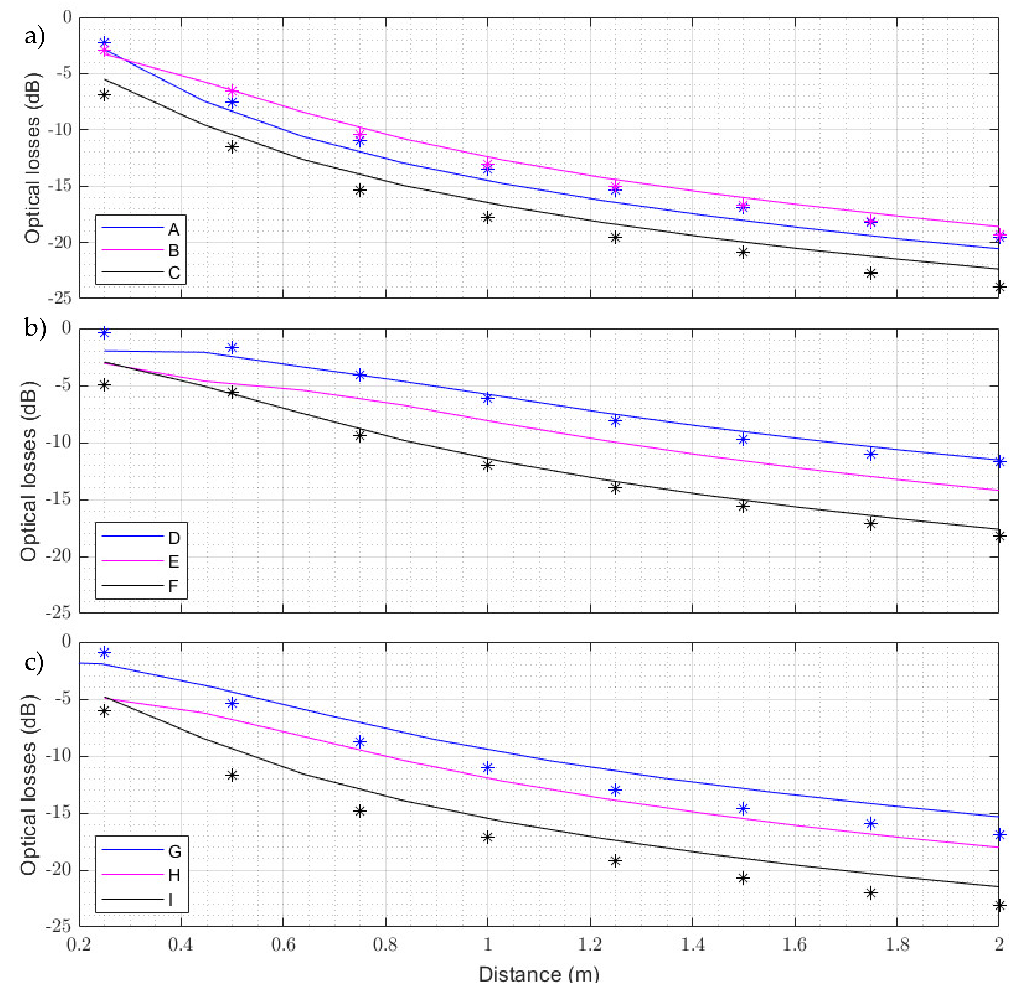
According to the simulation, with specific lenses at the fiber-output and at the photodetector input, signal losses can be obtained as a distance function. Figure 3a compares the optical losses as a function of distance using different lenses in the transmitter, whereas no lens is employed at the detector (setups A, B, and C). As expected from the theoretical predictions, the lens with the longest focal length produces the least beam divergence and therefore the divergence losses over the distance will be lower (setup B). Figure 3b shows the simulated optical losses as a function of distance by using the optimal lens for collimation (LA1951-A) and different lenses at the detector input (setups D, E and F). The aspheric lens ACL25416U-A (setup D) better concentrates the input beam on the photodetector due to the size of the focusing point (0.62 mm), small enough for the photodetector to capture it without power reduction. Besides, an aspheric lens introduces less loss in the detection system than a spherical lens due to the correction of the aberrations inherent to the geometry of spherical lenses. Lastly, the Prizmatix FCM05-05 collimator is tested at the fiber-output and different lenses are used at the detector input (G, H, and I setups), as shown in Figure 3c. In all cases, lower optical power is collected than in setups D, E, and F. Note that G setup leads to higher received optical power, although setup I shows the smallest spot size (1 mm), but higher losses are introduced due to the reduced lens size (1/2′).
Experimental measurements were done by using Thorlabs (Thorlabs Inc. Newton, New Jersey, USA) S130C photodiode power sensor and the PM100D power meter console under several setups for the sake of validation of simulation results. As shown in Figure 3, there is good agreement between theoretical results and experimental measurements in spite of differences between simulated models and real components. Therefore, setup D has been proved to be as the best option for the transmission system employed in this work.
Moreover, irradiance distribution is evaluated by nonsequential ray tracing in ZEMAX. The irradiance distribution variation can be shown as incoherent irradiance as a function of spatial position on the detector, as shown in Figure 4. The cross section corresponds to the photodetector (Ø1 mm). Three different cases are shown for the sake of comparison. First, no optics are used in the FSO link; second, only one collimating lens at the fiber-output is evaluated and no lens is employed at the receiver-end (setup B); finally, lens LA1951-A is employed at the fiber-output and lens ACL25416U-A at the receiver-end (setup D).
As shown in Figure 4a, the lack of an optical element at the fiber-output produces a highly divergent beam. The optical power incident on the photodiode over the distance is inadequate to establish communication. However, adding an optical element at the fiber-output to collimate the beam and homogenize the ray trajectories, as shown in Figure 4b, increases the incident power on the surface of the photodiode. Finally, by incorporating an optical element at the photodetector input, the collimated beam is concentrated (see Figure 4c) and thus the performance of the system is improved, as will be shown in the next section.

3. Transmission Measurements

3.1. Experimental Setup

In this section, we describe the experimental implementation of the single LED hybrid POF/VLC link. The basic blocks are shown in Figure 2a, where a digital QPSK or M-QAM signal is transmitted through a POF section followed by an OWC link. A low-cost LED (AVAGO SFH757) that emits light at a wavelength of 650 nm was employed as a transmitter. The LED is directly modulated in intensity over the linear region, with information-carrying signals generated by an arbitrary waveform generator (AWG, Tektronix 7122C). A carrier frequency of 60 MHz was chosen for all the employed modulation formats, while the signal bandwidth was modified between 10 and 115 MHz. This AWG generates a fixed electrical power of –1.5dBm, regardless of the modulation bandwidth. A Bias Tee (Mini-Circuit ZFBT-6GW+) is used to combine the DC bias current produced by a DC power supply (Keithley 2231A-30-3) and data signal from the AWG. The LED output is coupled into a 1.5 m long 1 mm step-index plastic fiber with 0.5 NA. The bare fiber is inserted directly into the LED housing. A collimating lens is placed at the fiber-output to create the wireless interface where an FC connector is employed at the fiber end. At the receiver-end, a lens is used to focus the light onto a Ø1 mm photodiode (Thorlabs, PDA10A) where the detected power is regulated by 1–12 dB ND absorption filters (Thorlabs, NEXXB). This photodetector incorporates a fixed gain TIA. Finally, the data is real-time demodulated on a digital phosphor oscilloscope (DPO, Tektronix 72004C).

3.2. System Performance for Different Bandwidths and Modulation Formats

This section reports the system performance obtained under two different lenses setup for the sake of comparison, i.e., setup H based on a commercial collimating solution and setup D proposed as the optimal solution in the previous section. Figure 5 shows the transmission results of three modulation formats, i.e., QPSK, 16-, and 64-QAM signals with different bandwidths under setup H (see Table 2) over 1 and 1.5 m of FSO link. The error vector magnitude (EVM) of the recovered signals was measured in order to test the viability of the setups and evaluate the maximum achievable capacity. The RoP at the detector over 1 m distance was –22.65 dBm, and the measured EVM results for the transmitted QPSK, 16-, and 64-QAM signals were below their valid maximum levels, which are 17.5%, 12.5%, and 8% [19], respectively, as shown in Figure 5a. Higher modulation orders have not been evaluated since they require lower EVM thresholds (i.e., 3.5% for 256-QAM) that can only be attained for shorter distances.
Figure 5b shows the obtained EVM measurements over 1.5 m FSO link using the same setup, in this case the RoP was –26.23 dBm, and the estimated bandwidths satisfying the corresponding EVM levels were estimated to be around 55 MHz, 25 MHz, and 5 MHz for QPSK, 16-, and 64-QAM, respectively. Finally, some tests were done over 2 m (RoP of –28.58 dBm), but only 20 MHz QPSK and 5 MHz 16-QAM signals gave EVM measurements under their reference levels.
By using the same setup (H), the EVM performance of the system was characterized in terms of RoP. As depicted in Figure 6, the EVM increases significantly with the signal bandwidth and decreases for larger RoP values. Figure 6a shows EVM measurements for different bandwidths using QPSK modulation and demonstrates that the transmission of a 60 MHz QPSK signal requires a received optical power of –22.8 dBm, while –21.8 dBm and –21.3 dBm RoP are required for 50 MHz 16-QAM and 28 MHz 64-QAM signals, respectively. Signal constellations at the highest measured bandwidths are shown as insets for –20.76 dBm RoP. If we compare the curves obtained with 10 MHz and 20 MHz bandwidths (or 20 and 40 MHz) for a fixed EVM (equivalent to a fixed SNR), there is a 1.5 dB RoP penalty that corresponds to a 3 dB difference in electrical power that comes from doubling the noise when the bandwidth is doubled. However, this relationship does not hold for larger bandwidths where other channel distortions apart from noise are present; then, the RoP penalty increases.
The following experiments employed setup D, which leads to maximum RoP according to Figure 3, which increases the capacity of the system. Figure 6 shows the EVM performance for different modulation formats vs. RoP and, in this case, transmission of 115 MHz QPSK signals was demonstrated with –16 dBm RoP, 65 MHz 16-QAM signal with –16.6 dBm and 45 MHz 64-QAM with –16.2 dBm. According to Figure 3b where optical losses was experimentally and theoretically characterized for different setups in terms of distance, this optical power level is achieved in setup D after 1.70 m free space optics propagation that is suitable for industrial applications, as described above. Constellations of the highest bandwidth signals are included as insets in Figure 7 for −15.7 dBm RoP.
In accordance with results depicted in Figure 3, setup D gives higher received optical power values, and, therefore, higher throughputs can be achieved using larger bandwidths and higher order M-QAM signals. To give a better insight, Figure 8 compares maximum achievable throughputs in terms of distance for both H and D setups. With setup D, a maximum throughput of 294 Mb/s can be achieved at 1.5 m, but as distance is increased, the RoP worsens and, since the noise level is fixed, the modulation bandwidth must be reduced, accordingly, giving a reduced bit rate. It can be seen that up to 2 m distance, 64-QAM is the best option giving throughputs higher than 200 Mb/s. For longer distances, the SNR reduction requires the use of QPSK with lower bandwidths as the distance increases, giving at 2.8 m a bit rate of 80 Mb/s, which is also suitable for industrial connectivity. At lower distances the QPSK throughput is limited by the 110 MHz maximum bandwidth of the employed components. On the other hand, when the H setup is chosen, the lower RoP makes more interesting the use of 16-QAM instead of 64-QAM, and again, an increasing distance requires a reduction of bandwidth until 1.3 m; from this point, a QPSK modulation should be used.

4. Conclusions

In this paper, we have proposed the use of a centralized LED with no intermediate electro-optical conversion stages for optical fiber-wireless links. Simulations of the optics required in the interfaces have been carried out to provide the main guidelines for an optimized design, and the obtained results have been experimentally validated. As a result, we have experimentally demonstrated a 294 Mb/s VLC system using a hybrid POF/VLC link based on a single LED for indoor communications. The lack of optical sources in the fiber-to-LED interface, as well as the wired-wireless hybrid links, provides an attractive solution for massive low consumption and flexible implementation of communications links in Industry 4.0.

Author Contributions

Conceptualization, B.O. and V.A.; software, J.A.A.; validation, B.O.; data acquisition, J.A.A.; writing—original draft preparation, B.O. and J.A.A.; supervision, B.O. and V.A. All authors have read and agreed to the published version of the manuscript.

Funding

This work was supported by the Spanish Ministerio de Ciencia, Innovación y Universidades RTI2018-101658-B-I00 FOCAL project.

Institutional Review Board Statement

Not applicable.

Informed consent statement

Not applicable.

Data Availability Statement

Not applicable.

Acknowledgments

COST action NEWFOCUS (CA19111).

Conflicts of Interest

The authors declare no conflict of interest.

References

  1. Schwab, K. The Fourth Industrial Revolution; World Economic Forum: Geneva, Switzerland, 2016. [Google Scholar]
  2. Zhang, X.; Cao, Z.; Li, J.; Ge, D.; Chen, Z.; Vellekoop, I.M.; Koonen, A.M.J. Wide-Coverage Beam-Steered 40-Gbit/s Non-Line-of-Sight Optical Wireless Connectivity for Industry 4.0. J. Light. Technol. 2020, 38, 6801–6806. [Google Scholar] [CrossRef]
  3. Sabella, R.; Iovanna, P.; Bottari, G.; Cavaliere, F. Optical transport for Industry 4.0. J. Opt. Commun. Netw. 2020, 12, 264–276. [Google Scholar] [CrossRef]
  4. Kouhini, S.M.; Jarchlo, E.A.; Ferreira, R.; Khademi, S.; Maierbacher, G.; Siessegger, B.; Schulz, D.; Hilt, J.; Hellwig, P.; Jungnickel, V. Use of Plastic Optical Fibers for Distributed MIMO in Li-Fi Systems. In Proceedings of the 2019 Global LIFI Congress (GLC), Paris, France, 12–13 June 2019; pp. 1–5. [Google Scholar]
  5. Berenguer, P.W.; Schulz, D.; Hilt, J.; Hellwig, P.; Kleinpeter, G.; Fischer, J.K.; Jungnickel, V. Optical Wireless MIMO Experiments in an Industrial Environment. IEEE J. Sel. Areas Commun. 2018, 36, 185–193. [Google Scholar] [CrossRef]
  6. Haas, H. LiFi is a paradigm-shifting 5G technology. Rev. Phys. 2018, 3, 26–31. [Google Scholar] [CrossRef]
  7. Bian, R.; Tavakkolnia, I.; Haas, H. 15.73 Gb/s Visible Light Communication with off-the-shelf LEDs. J. Light. Technol. 2019, 37, 2418–2424. [Google Scholar] [CrossRef] [Green Version]
  8. Chen, Q.; Han, D.; Zhang, M.; Ghassemlooy, Z.; Boucouvalas, A.C.; Zhang, Z.; Li, T.; Jiang, X. Design and Demonstration of a TDD-Based Central-Coordinated Resource-Reserved Multiple Access (CRMA) Scheme for Bidirectional VLC Networking. IEEE Access 2021, 9, 7856–7868. [Google Scholar] [CrossRef]
  9. Younus, O.I.; Le Minh, H.; Dat, P.T.; Yamamoto, N.; Pham, A.T.; Ghassemlooy, Z. Dynamic Physical-Layer Secured Link in a Mobile MIMO VLC System. IEEE Photon. J. 2020, 12, 1–14. [Google Scholar] [CrossRef]
  10. Tsonev, D.; Videv, S.; Haas, H. Towards a 100 Gb/s visible light wireless access network. Opt. Exp. 2015, 23, 1627–1637. [Google Scholar] [CrossRef] [PubMed]
  11. Osahon, I.N.; Pikasis, E.; Rajbhandari, S.; Popoola, W.O. Hybrid POF/VLC link with M-PAM and MLP equaliser. In Proceedings of the 2017 IEEE International Conference on Communications (ICC), Paris, France, 21–25 May 2017; pp. 1–6. [Google Scholar]
  12. Lin, C.-Y.; Li, C.-Y.; Lu, H.-H.; Chang, C.-H.; Peng, P.-C.; Lin, C.-R.; Chen, J.-H. A Hybrid CATV/16-QAM-OFDM In-House Network Over SMF and GI-POF/VLC Transport. IEEE Photon. Technol. Lett. 2015, 27, 526–529. [Google Scholar] [CrossRef]
  13. Joncic, M.; Kruglov, R.; Haupt, M.; Caspary, R.; Vinogradov, J.; Fischer, U.H.P. Four-Channel WDM Transmission Over 50-m SI-POF at 14.77 Gb/s Using DMT Modulation. IEEE Photon. Technol. Lett. 2014, 26, 1328–1331. [Google Scholar] [CrossRef]
  14. Li, X.; Bamiedakis, N.; Wei, J.; McKendry, J.J.D.; Xie, E.; Ferreira, R.; Gu, E.; Dawson, M.D.; Penty, R.V.; White, I.H. μLED-Based Single-Wavelength Bi-directional POF Link with 10 Gb/s Aggregate Data Rate. J. Light. Technol. 2015, 33, 3571–3576. [Google Scholar] [CrossRef] [Green Version]
  15. Correa, C.; Huijskens, F.; Tangdiongga, E.; Koonen, A. Luminaire-Free Gigabits per second LiFi Transmission employing WDM-over-POF. In Proceedings of the 2020 European Conference on Optical Communications (ECOC), Brussels, Belgium, 6–10 December 2020; pp. 1–4. [Google Scholar]
  16. Nuwanpriya, A.; Ho, S.-W.; Chen, C.S. Indoor MIMO Visible Light Communications: Novel Angle Diversity Receivers for Mobile Users. IEEE J. Sel. Areas Commun. 2015, 33, 1780–1792. [Google Scholar] [CrossRef]
  17. Prizmatix Home Page. Available online: https://www.prizmatix.com/Optics/Collimator.htm (accessed on 28 April 2021).
  18. Mahajan, V.N. Fundamentals of Geometrical Optics; SPIE Press: Washington, WA, USA, 2014. [Google Scholar]
  19. TS 138.101-1 V15.5.0. User equipment (UE) radio transmission and reception: Part 2: Range 2 standalone, 2019. ETSI Home Page. Available online: https://www.etsi.org/deliver/etsi_ts/138100_138199/13810102/15.05.00_60/ts_13810102v150500p.pdf (accessed on 10 April 2021).
Figure 1. VLC-based infrastructure proposed for factory networks. DL: downlink, UL: uplink.
Photonics 08 00254 g001
Figure 2. General scheme of the hybrid link: (a) block diagram of the experimental setup for the POF-VLC system, and (b) detail of FSO block: ray tracing diagram.
Photonics 08 00254 g002
Figure 3. Experimental (symbols) and simulated (solid lines) optical losses vs. distance for different setups at the VLC link (defined in Table 2): (a) different lenses at the fiber-output and no lens at the receiver; (b) setups D, E, and F (Lens LA1951 is employed at the fiber-output in all of them); and (c) setups G, H, and I (FCM05-05 is employed at the fiber-output in all of them).
Photonics 08 00254 g003
Figure 4. Rays trajectory and the corresponding cross section at the receiver: (a) no lenses are employed, (b) lens LA1951-A is employed at the fiber-output and no lens at the receiver-end (setup B), and (c) lens LA1951-A is employed at the fiber-output and ACL25416U-A at the receiver-end (setup D).
Photonics 08 00254 g004
Figure 5. EVM measurements for setup H under different bandwidths and modulation formats at different distances: (a) 1 m, (b) 1.5 m.
Photonics 08 00254 g005
Figure 6. EVM performance vs RoP for different bandwidth signals (Setup H): (a) QPSK modulation, (b) 16-QAM modulation, and (c) 64-QAM modulation.
Photonics 08 00254 g006
Figure 7. EVM performance vs RoP for different bandwidth signals (setup D): (a) QPSK modulation, (b) 16-QAM modulation, and (c) 64-QAM modulation.
Photonics 08 00254 g007
Figure 8. Throughput vs. FSO distance for different modulation formats in setups D and H.
Photonics 08 00254 g008
Table 1. Optical characteristics of the employed lenses.
Commercial
Lenses
Diameter
(mm)
Focal Length
(mm)
Back Focal Length
(mm)
NAGeometryDivergence α (deg)
LA1951-A25.425.317.60.5Spherical2.26
ACL25416U-A25.416.07.30.79Aspherical3.58
ACL50832U50.832170.76Aspherical1.80
FCM05-0512.7~ 12*0.5Spherical5.73
* no info.
Table 2. Lenses employed at both ends of the VLC link in different setups and corresponding obtained spot sizes at the PD input.
Setup ASetup BSetup CSetup DSetup ESetup FSetup GSetup HSetup I
Fiber-outputACL25416U-ALA1951-AFCM05-05LA1951-ALA1951-ALA1951-AFCM05-05FCM05-05FCM05-05
Receiver end------ACL25416U-ALA1951-AFCM05-05ACL25416U-ALA1951-AFCM05-05
Spot size (mm)------0.6210.471.332.11
Publisher’s Note: MDPI stays neutral with regard to jurisdictional claims in published maps and institutional affiliations.

