Soft X-ray Lensless Imaging in Reflection Mode

 , ,
, , 
Abstract
:1. Introduction
2. Materials and Methods
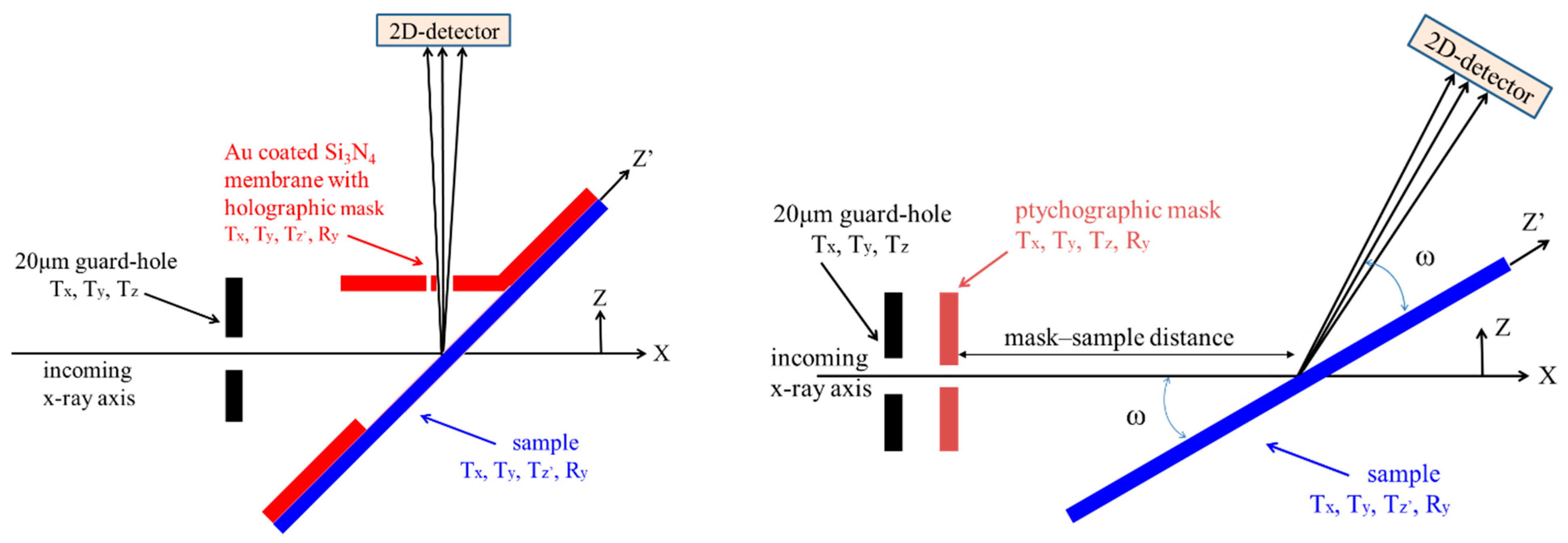
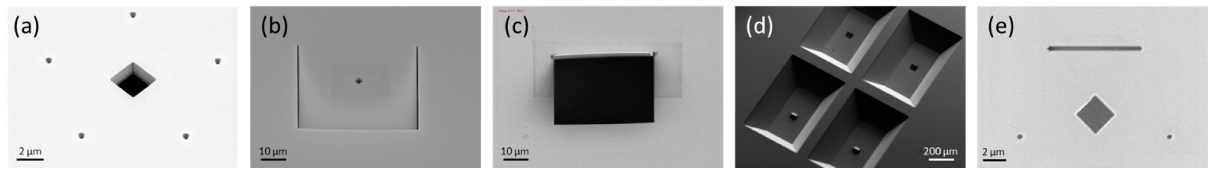
2.1. Holographic Mask
2.2. Ptychographic Mask
3. Results
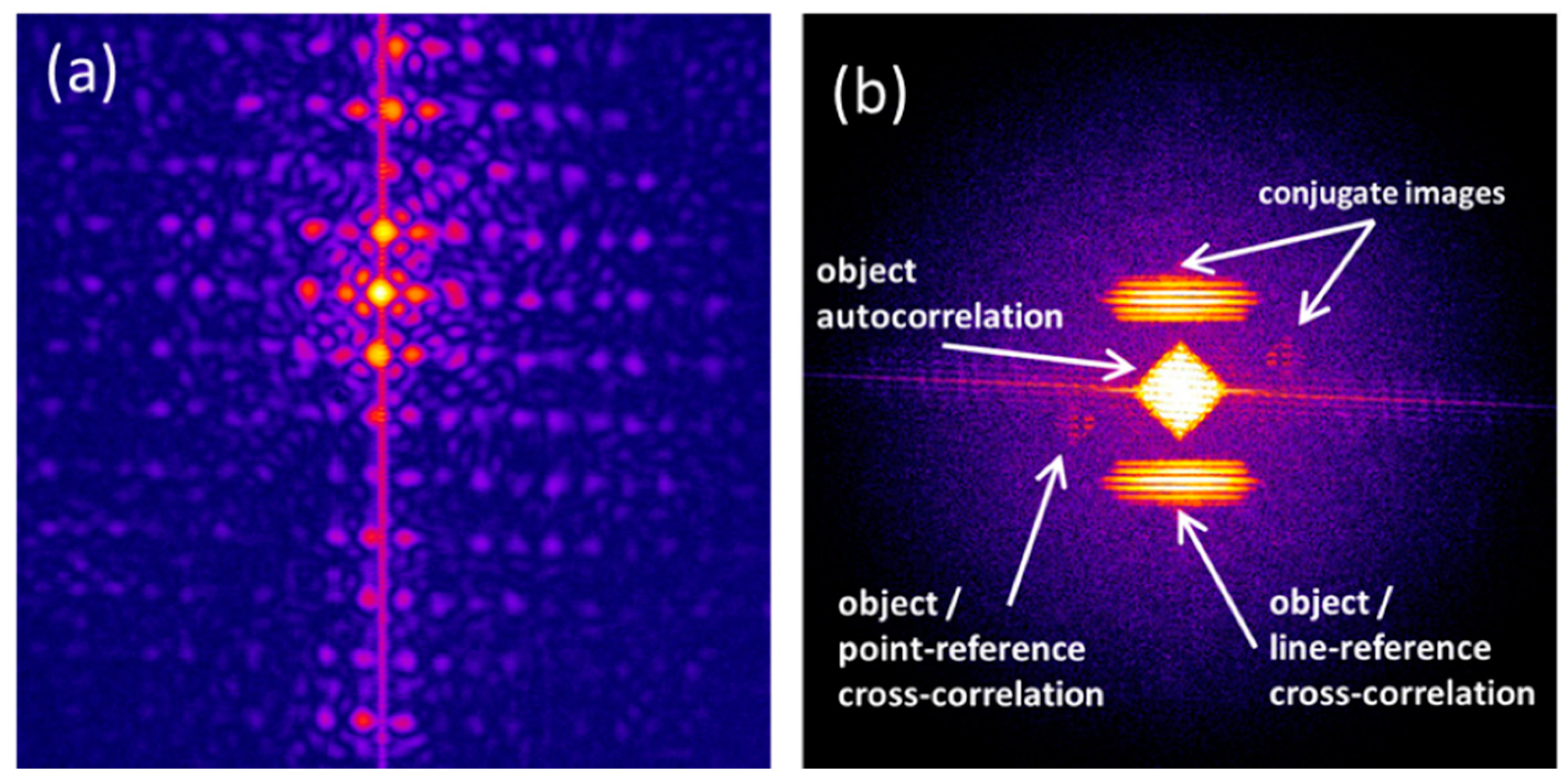
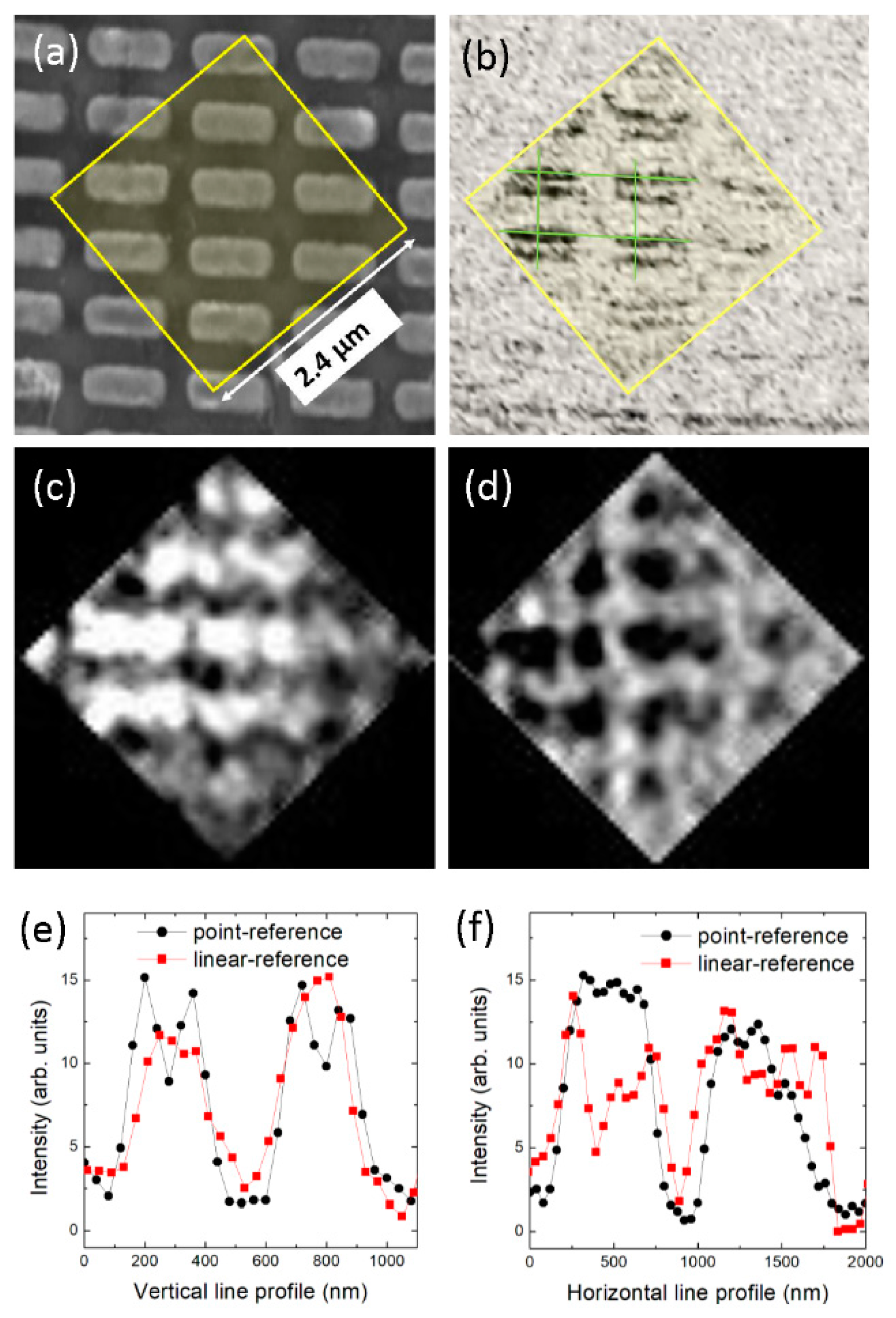
3.1. Holography
3.2. Ptychography
4. Discussion
Author Contributions
Funding
Data Availability Statement
Acknowledgments
Conflicts of Interest
References
- Fink, J.; Schierle, E.; Weschke, E.; Geck, J. Resonant elastic soft X-ray scattering. Rep. Prog. Phys. 2013, 76, 056502. [Google Scholar] [CrossRef]
- Spezzani, C.; Ferrari, E.; Allaria, E.; Vidal, F.; Ciavardini, A.; Delaunay, R.; Capotondi, F.; Pedersoli, E.; Coreno, M.; Svetina, C.; et al. Magnetization and microstructure dynamics in Fe/MnAs/GaAs(001): Fe magnetization reversal by a femtosecond laser pulse. Phys. Rev. Lett. 2014, 113, 247202. [Google Scholar] [CrossRef] [Green Version]
- Buzzi, M.; Först, M.; Mankowsky, R.; Cavalleri, A. Probing dynamics in quantum materials with femtosecond X-rays. Nat. Rev. Mater. 2018, 3, 299. [Google Scholar] [CrossRef] [Green Version]
- Holldack, K.; Pontius, N.; Schierle, E.; Kachel, T.; Soltwisch, V.; Mitzner, R.; Quast, T.; Springholz, G.; Weschke, E. Ultrafast dynamics of antiferromagnetic order studied by femtosecond resonant soft X-ray diffraction. Appl. Phys. Lett. 2010, 97, 062502. [Google Scholar] [CrossRef]
- Pontius, N.; Kachel, T.; Schüßler-Langeheine, C.; Schlotter, W.F.; Beye, M.; Sorgenfrei, F.; Chang, C.-F.; Föhlisch, A.; Wurth, W.; Metcalf, P.; et al. Time-resolved resonant soft x-ray diffraction with free-electron lasers: Femtosecond dynamics across the Verwey transition in magnetite. Appl. Phys. Lett. 2011, 98, 182504. [Google Scholar] [CrossRef] [Green Version]
- Ehrke, H.; Tobey, R.I.; Wall, S.; Cavill, S.A.; Först, M.; Khanna, V.; Garl, T.; Stojanovic, N.; Prabhakaran, D.; Boothroyd, A.T.; et al. Photoinduced melting of antiferromagnetic order in La0.5Sr1.5MnO4 measured using ultrafast resonant soft X-ray diffraction. Phys. Rev. Lett. 2011, 106, 217401. [Google Scholar] [CrossRef] [Green Version]
- Johnson, S.L.; De Souza, R.A.; Staub, U.; Beaud, P.; Möhr-Vorobeva, E.; Ingold, G.; Caviezel, A.; Scagnoli, V.; Schlotter, W.F.; Turner, J.J.; et al. Femtosecond dynamics of the collinear-to-spiral antiferromagnetic phase transition in CuO. Phys. Rev. Lett. 2012, 108, 037203. [Google Scholar] [CrossRef] [PubMed] [Green Version]
- Kubacka, T.; Johnson, J.A.; Hoffmann, M.C.; Vicario, C.; de Jong, S.; Beaud, P.; Grübel, S.; Huang, S.-W.; Huber, L.; Patthey, L.; et al. Large-amplitude spin dynamics driven by a THz pulse in resonance with an electromagnon. Science 2014, 343, 1333–1336. [Google Scholar] [CrossRef] [PubMed] [Green Version]
- Chauleau, J.-Y.; Legrand, W.; Reyren, N.; Maccariello, D.; Collin, S.; Popescu, H.; Bouzehouane, K.; Cros, V.; Jaouen, N.; Fert, A. Chirality in magnetic multilayers probed by the symmetry and the amplitude of dichroism in X-ray resonant magnetic scattering. Phys. Rev. Lett. 2018, 120, 037202. [Google Scholar] [CrossRef] [PubMed] [Green Version]
- Chauleau, J.-Y.; Chirac, T.; Fusil, S.; Garcia, V.; Akhtar, W.; Tranchida, J.; Thibaudeau, P.; Gross, I.; Blouzon, C.; Finco, A.; et al. Electric and antiferromagnetic chiral textures at multiferroic domain walls. Nat. Mater. 2020, 19, 386–390. [Google Scholar] [CrossRef]
- Lee, W.; Chuang, Y.; Moore, R.; Zhu, Y.; Patthey, L.; Trigo, M.; Lu, D.; Kirchmann, P.; Krupin, O.; Yi, M.; et al. Phase fluctuations and the absence of topological defects in a photo-excited charge-ordered nickelate. Nat. Commun. 2012, 3, 838. [Google Scholar] [CrossRef] [Green Version]
- Chuang, Y.D.; Lee, W.S.; Kung, Y.F.; Sorini, A.P.; Moritz, B.; Moore, R.G.; Patthey, L.; Trigo, M.; Lu, D.H.; Kirchmann, P.S.; et al. Real-time manifestation of strongly coupled spin and charge order parameters in stripe-ordered La1.75Sr0.25NiO4 nickelate crystals using time-resolved resonant X-ray diffraction. Phys. Rev. Lett. 2013, 110, 127404. [Google Scholar] [CrossRef] [Green Version]
- Mitrano, M.; Lee, S.; Husain, A.A.; Delacretaz, L.; Zhu, M.; Munoz, G.D.L.P.; Sun, S.X.-L.; Joe, Y.I.; Reid, A.H.; Wandel, S.F.; et al. Ultrafast time-resolved X-ray scattering reveals diffusive charge order dynamics in La2−xBaxCuO4. Sci. Adv. 2019, 5. [Google Scholar] [CrossRef] [Green Version]
- Ehrke, H.; Tobey, R.I.; Wall, S.; Cavill, S.A.; Prabhakaran, D.; Boothroyd, A.T.; Gensch, M.; Reutler, P.; Revcolevschi, A.; Dhesi, S.S.; et al. Ultrafast resonant soft X-ray scattering in manganites: Direct measurement of time-dependent orbital order. In Proceedings of the International Conference on Ultrafast Phenomena, Snowmass, CO, USA, 18–23 July 2010. [Google Scholar]
- Zwiebler, M.; Borrero, J.E.H.; Vafaee, M.; Komissinskiy, P.; Macke, S.; Sutarto, R.; He, F.; Büchner, B.; Sawatzky, G.A.; Alff, L.; et al. Electronic depth profiles with atomic layer resolution from resonant soft x-ray reflectivity. New J. Phys. 2015, 17, 83046. [Google Scholar] [CrossRef] [Green Version]
- Jal, E.; López-Flores, V.; Pontius, N.; Ferté, T.; Bergeard, N.; Boeglin, C.; Vodungbo, B.; Lüning, J.; Jaouen, N. Structural dynamics during laser-induced ultrafast demagnetization. Phys. Rev. B 2017, 95, 184422. [Google Scholar] [CrossRef] [Green Version]
- Eisebitt, S.; Lüning, J.; Schlotter, W.F.; Lörgen, M.; Hellwig, O.; Eberhardt, W.; Stöhr, J. Lensless imaging of magnetic nanostructures by X-ray spectro-holography. Nat. Cell Biol. 2004, 432, 885–888. [Google Scholar] [CrossRef] [Green Version]
- Spezzani, C.; Fortuna, F.; Delaunay, R.; Popescu, H.; Sacchi, M. X-ray holographic imaging of magnetic order in patterned Co/Pd multilayers. Phys. Rev. B 2013, 88, 224420. [Google Scholar] [CrossRef]
- Beckers, M.; Senkbeil, T.; Gorniak, T.; Reese, M.; Giewekemeyer, K.; Gleber, S.-C.; Salditt, T.; Rosenhahn, A. Chemical contrast in soft X-ray ptychography. Phys. Rev. Lett. 2011, 107, 208101. [Google Scholar] [CrossRef] [PubMed]
- Shapiro, D.A.; Yu, Y.-S.; Tyliszczak, T.; Cabana, J.; Celestre, R.; Chao, W.; Kaznatcheev, K.; Kilcoyne, A.; Maia, F.R.N.C.; Marchesini, S.; et al. Chemical composition mapping with nanometre resolution by soft X-ray microscopy. Nat. Photonics 2014, 8, 765–769. [Google Scholar] [CrossRef] [Green Version]
- Shi, X.; Fischer, P.; Neu, V.; Elefant, D.; Lee, J.C.T.; Shapiro, D.A.; Farmand, M.; Tyliszczak, T.; Shiu, H.-W.; Marchesini, S.; et al. Soft X-ray ptychography studies of nanoscale magnetic and structural correlations in thin SmCo5 films. Appl. Phys. Lett. 2016, 108, 094103. [Google Scholar] [CrossRef] [Green Version]
- Vedmedenko, E.Y.; Kawakami, R.K.; Sheka, D.D.; Gambardella, P.; Kirilyuk, A.; Hirohata, A.; Binek, C.; Chubykalo-Fesenko, O.; Sanvito, S.; Kirby, B.J.; et al. The 2020 magnetism roadmap. J. Phys. D Appl. Phys. 2020, 53, 453001. [Google Scholar] [CrossRef]
- Sacchi, M.; Spezzani, C.; Carpentiero, A.; Prasciolu, M.; Delaunay, R.; Luning, J.; Polack, F. Experimental setup for lensless imaging via soft X-ray resonant scattering. Rev. Sci. Instrum. 2007, 78, 43702. [Google Scholar] [CrossRef] [PubMed]
- Stickler, D.; Frömter, R.; Stillrich, H.; Menk, C.; Tieg, C.; Streit-Nierobisch, S.; Sprung, M.; Gutt, C.; Stadler, L.-M.; Leupold, O.; et al. Soft X-ray holographic microscopy. Appl. Phys. Lett. 2010, 96, 042501. [Google Scholar] [CrossRef] [Green Version]
- Tieg, C.; Frömter, R.; Stickler, D.; Hankemeier, S.; Philippi-Kobs, A.; Streit-Nierobisch, S.; Gutt, C.; Grübel, G.; Oepen, H.P. Imaging the in-plane magnetization in a Co microstructure by Fourier transform holography. Opt. Express 2010, 18, 27251–27256. [Google Scholar] [CrossRef]
- Popescu, H.; Fortuna, F.; Delaunay, R.; Spezzani, C.; Lopez-Flores, V.; Jaouen, N.; Sacchi, M. Four-state magnetic configuration in a tri-layer asymmetric ring. Appl. Phys. Lett. 2015, 107, 202404. [Google Scholar] [CrossRef]
- Sacchi, M.; Popescu, H.; Jaouen, N.; Tortarolo, M.; Fortuna, F.; Delaunay, R.; Spezzani, C. Magnetic imaging by Fourier transform holography using linearly polarized X-rays. Opt. Express 2012, 20, 9769–9776. [Google Scholar] [CrossRef] [PubMed]
- Willems, F.; Schmising, C.V.K.; Weder, D.; Günther, C.M.; Schneider, M.; Pfau, B.; Meise, S.; Guehrs, E.; Geilhufe, J.; Merhe, A.E.D.; et al. Multi-color imaging of magnetic Co/Pt heterostructures. Struct. Dyn. 2017, 4, 014301. [Google Scholar] [CrossRef] [PubMed]
- Wang, T.; Zhu, D.; Wu, B.; Graves, C.; Schaffert, S.; Rander, T.; Müller, L.; Vodungbo, B.; Baumier, C.; Bernstein, D.P.; et al. Femtosecond single-shot imaging of nanoscale ferromagnetic order in Co/Pd multilayers using resonant X-ray holography. Phys. Rev. Lett. 2012, 108, 267403. [Google Scholar] [CrossRef] [Green Version]
- Bergeard, N.; Schaffert, S.; Lopez-Flores, V.; Jaouen, N.; Geilhufe, J.; Günther, C.M.; Schneider, M.; Graves, C.; Wang, T.; Wu, B.; et al. Irreversible transformation of ferromagnetic ordered stripe domains in single-shot infrared-pump/resonant-x-ray-scattering-probe experiments. Phys. Rev. B 2015, 91, 054416. [Google Scholar] [CrossRef] [Green Version]
- Gardner, D.F.; Zhang, B.; Seaberg, M.D.; Martin, L.S.; Adams, D.E.; Salmassi, F.; Gullikson, E.; Kapteyn, H.; Murnane, M. High numerical aperture reflection mode coherent diffraction microscopy using off-axis apertured illumination. Opt. Express 2012, 20, 19050–19059. [Google Scholar] [CrossRef]
- Zürch, M.; Kern, C.; Spielmann, C. XUV coherent diffraction imaging in reflection geometry with low numerical aperture. Opt. Express 2013, 21, 21131–21147. [Google Scholar] [CrossRef] [PubMed]
- Roy, S.; Parks, D.; Seu, K.A.; Su, R.; Turner, J.J.; Chao, W.; Anderson, E.H.; Cabrini, S.; Kevan, S. Lensless X-ray imaging in reflection geometry. Nat. Photonics 2011, 5, 243–245. [Google Scholar] [CrossRef]
- Guehrs, E.; Günther, C.M.; Pfau, B.; Rander, T.; Schaffert, S.; Schlotter, W.F.; Eisebitt, S. Wavefield back-propagation in high-resolution X-ray holography with a movable field of view. Opt. Express 2010, 18, 18922–18931. [Google Scholar] [CrossRef]
- Gerchberg, R.W.; Saxton, W.O. A practical algorithm for the determination of phase from image and diffraction plane pictures. Optik 1972, 35, 227. [Google Scholar]
- Maiden, A.M.; Rodenburg, J. An improved ptychographical phase retrieval algorithm for diffractive imaging. Ultramicroscopy 2009, 109, 1256–1262. [Google Scholar] [CrossRef]
- Pfeiffer, F. X-ray ptychography. Nat. Photonics 2017, 12, 9–17. [Google Scholar] [CrossRef]
- Sacchi, M.; Popescu, H.; Gaudemer, R.; Jaouen, N.; Avila, A.; Delaunay, R.; Fortuna, F.; Maier, U.; Spezzani, C. IRMA-2 at SOLEIL: A set-up for magnetic and coherent scattering of polarized soft X-rays. J. Phys. Conf. Ser. 2013, 425, 202009. [Google Scholar] [CrossRef]
- Sacchi, M.; Jaouen, N.; Popescu, H.; Gaudemer, R.; Tonnerre, J.M.; Chiuzbăian, S.G.; Hague, C.F.; Delmotte, A.; Dubuisson, J.M.; Cauchon, G.; et al. The SEXTANTS beamline at SOLEIL: A new facility for elastic, inelastic and coherent scattering of soft X-rays. J. Phys. Conf. Ser. 2013, 425, 072018. [Google Scholar] [CrossRef] [Green Version]
- Spezzani, C.; Fabrizioli, M.; Candeloro, P.; Di Fabrizio, E.; Panaccione, G.; Sacchi, M. Magnetic order in a submicron patterned permalloy film studied by resonant X-ray scattering. Phys. Rev. B 2004, 69, 224412. [Google Scholar] [CrossRef]
- Fortuna, F.; Spezzani, C.; Delaunay, R.; Popescu, H.; Sacchi, M. Testing a New Set-Up for X-ray Holographic Imaging in Reflectivity Mode. 2013. Available online: https://www.researchgate.net/publication/356361282_Testing_a_new_set-up_for_x-ray_holographic_imaging_in_reflectivity_mode?channel=doi&linkId=6196ce2661f0987720b27f7e&showFulltext=true (accessed on 10 December 2021). [CrossRef]
- Li, J.; Liu, Z. Focused-ion-beam-based nano-kirigami: From art to photonics. Nanophotonics 2018, 7, 1637–1650. [Google Scholar] [CrossRef]
- Chen, S.; Chen, J.; Zhang, X.; Li, Z.-Y.; Li, J. Kirigami/origami: Unfolding the new regime of advanced 3D microfabrication/nanofabrication with “folding”. Light. Sci. Appl. 2020, 9, 75. [Google Scholar] [CrossRef]
- Guizar-Sicairos, M.; Fienup, J. Holography with extended reference by autocorrelation linear differential operation. Opt. Express 2007, 15, 17592–17612. [Google Scholar] [CrossRef]
- Zhu, D.; Guizar-Sicairos, M.; Wu, B.; Scherz, A.; Acremann, Y.; Tyliszczak, T.; Fischer, P.; Friedenberger, N.; Ollefs, K.J.; Farle, M.; et al. High-resolution X-ray lensless imaging by differential holographic encoding. Phys. Rev. Lett. 2010, 105, 043901. [Google Scholar] [CrossRef] [Green Version]
- Duckworth, T.A.; Ogrin, F.; Dhesi, S.S.; Langridge, S.; Whiteside, A.; Moore, T.; Beutier, G.; Van Der Laan, G. Magnetic imaging by X-ray holography using extended references. Opt. Express 2011, 19, 16223–16228. [Google Scholar] [CrossRef] [Green Version]
- Bukin, N.; McKeever, C.; Burgos-Parra, E.; Keatley, P.S.; Hicken, R.J.; Ogrin, F.Y.; Beutier, G.; Dupraz, M.; Popescu, H.; Jaouen, N.; et al. Time-resolved imaging of magnetic vortex dynamics using holography with extended reference autocorrelation by linear differential operator. Sci. Rep. 2016, 6, 36307. [Google Scholar] [CrossRef] [PubMed] [Green Version]
- Loudon, J.C.; Twitchett-Harrison, A.C.; Cortés-Ortuño, D.; Birch, M.T.; Turnbull, L.A.; Štefančič, A.; Ogrin, F.Y.; Burgos-Parra, E.O.; Bukin, N.; Laurenson, A.; et al. Do images of biskyrmions show type-II bubbles? Adv. Mater. 2019, 31, e1806598. [Google Scholar] [CrossRef] [Green Version]
- Popescu, H.; Perron, J.; Pilette, B.; Vacheresse, R.; Pinty, V.; Gaudemer, R.; Sacchi, M.; Delaunay, R.; Fortuna, F.; Medjoubi, K.; et al. COMET: A new end-station at SOLEIL for coherent magnetic scattering in transmission. J. Synchrotron Radiat. 2019, 26, 280–290. [Google Scholar] [CrossRef]
- Medjoubi, K.; Baranton, G.; Somogyi, A. Fast full-field micro-tomography at the Nanoscopium multitechnique nanoprobe beamline of Synchrotron Soleil. Microsc. Microanal. 2018, 24, 254–255. [Google Scholar] [CrossRef] [Green Version]
- Schlotter, W.F.; Rick, R.; Chen, K.; Scherz, A.; Stohr, J.; Luning, J.; Eisebitt, S.; Gunther, C.; Eberhardt, W.; Hellwig, O.; et al. Multiple reference Fourier transform holography with soft X-rays. Appl. Phys. Lett. 2006, 89, 163112. [Google Scholar] [CrossRef] [Green Version]


Publisher’s Note: MDPI stays neutral with regard to jurisdictional claims in published maps and institutional affiliations. |
© 2021 by the authors. Licensee MDPI, Basel, Switzerland. This article is an open access article distributed under the terms and conditions of the Creative Commons Attribution (CC BY) license (https://creativecommons.org/licenses/by/4.0/).
Share and Cite
Popescu, H.; Fortuna, F.; Delaunay, R.; Jaouen, N.; Spezzani, C.; Sacchi, M. Soft X-ray Lensless Imaging in Reflection Mode. Photonics 2021, 8, 569. https://doi.org/10.3390/photonics8120569
Popescu H, Fortuna F, Delaunay R, Jaouen N, Spezzani C, Sacchi M. Soft X-ray Lensless Imaging in Reflection Mode. Photonics. 2021; 8(12):569. https://doi.org/10.3390/photonics8120569
Chicago/Turabian StylePopescu, Horia, Franck Fortuna, Renaud Delaunay, Nicolas Jaouen, Carlo Spezzani, and Maurizio Sacchi. 2021. "Soft X-ray Lensless Imaging in Reflection Mode" Photonics 8, no. 12: 569. https://doi.org/10.3390/photonics8120569