Refractive Index Sensing Based on Multiple Fano Resonances in a Split-Ring Cavity-Coupled MIM Waveguide


Abstract
:1. Introduction
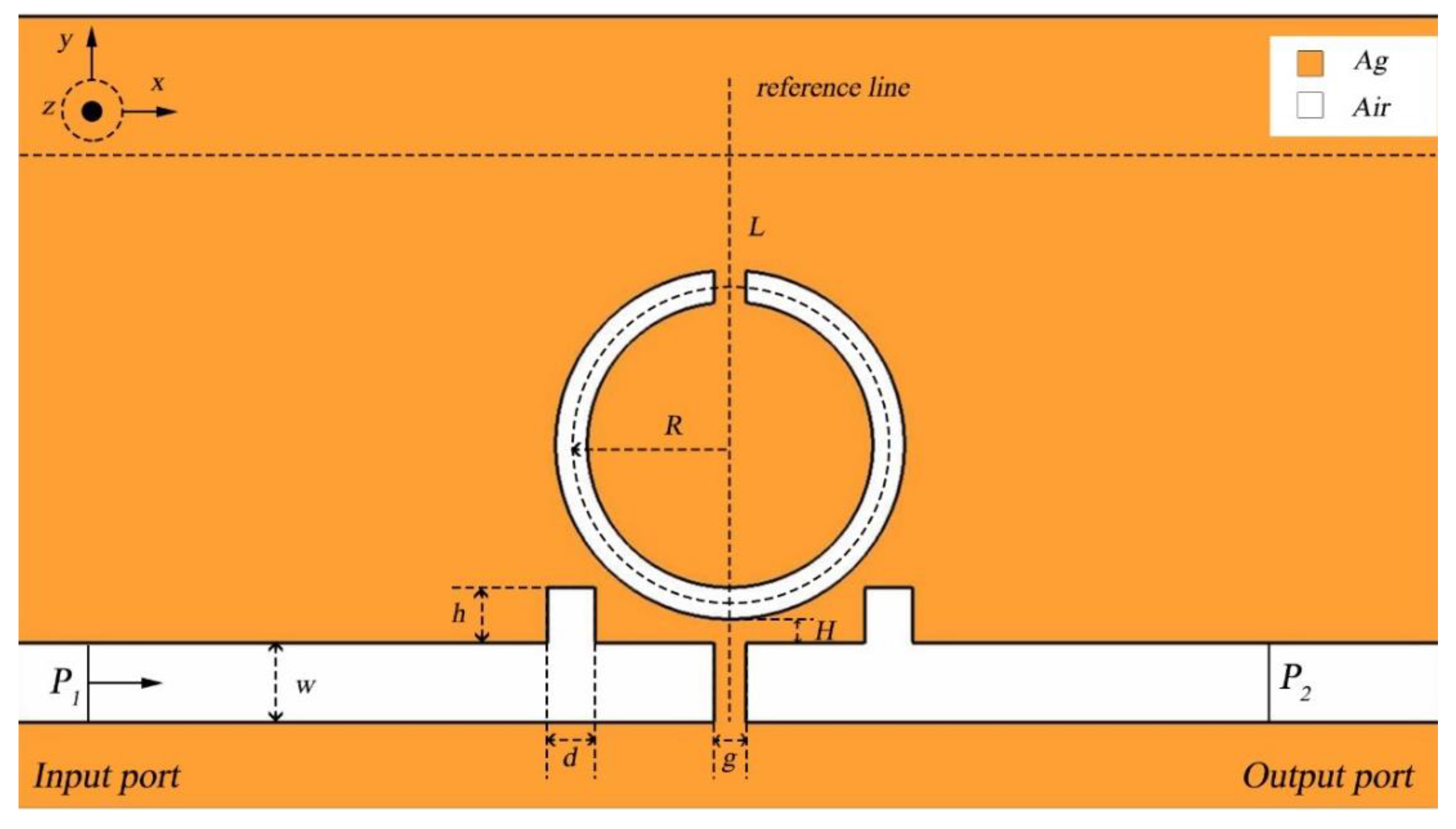
2. Structure and Method
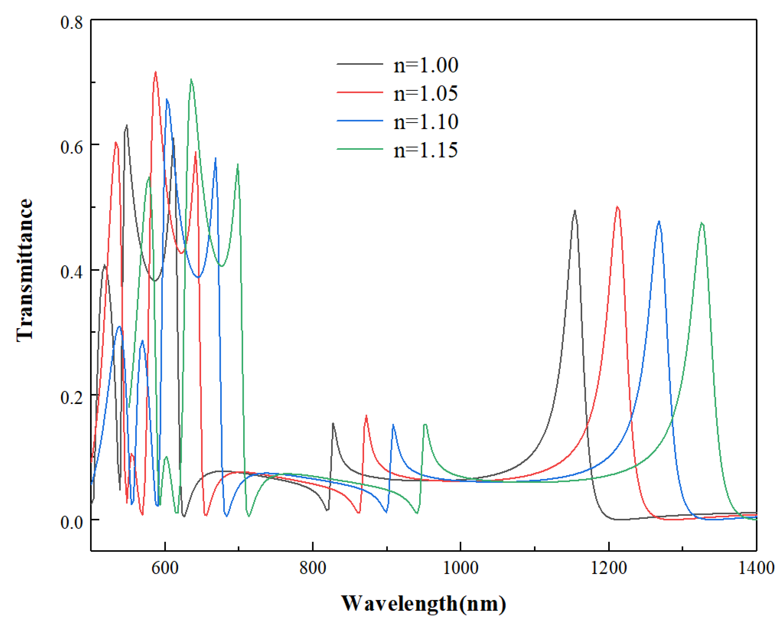
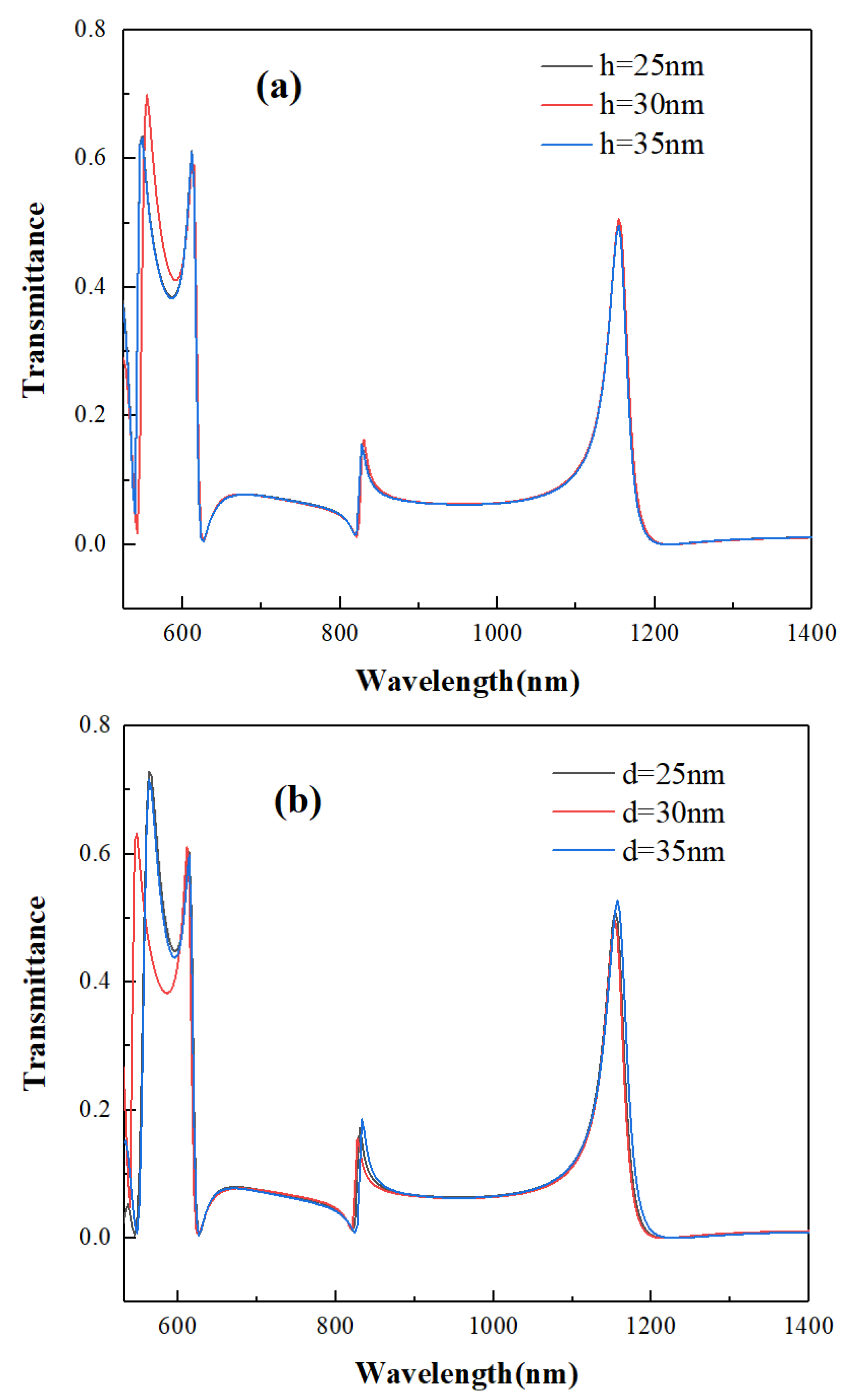
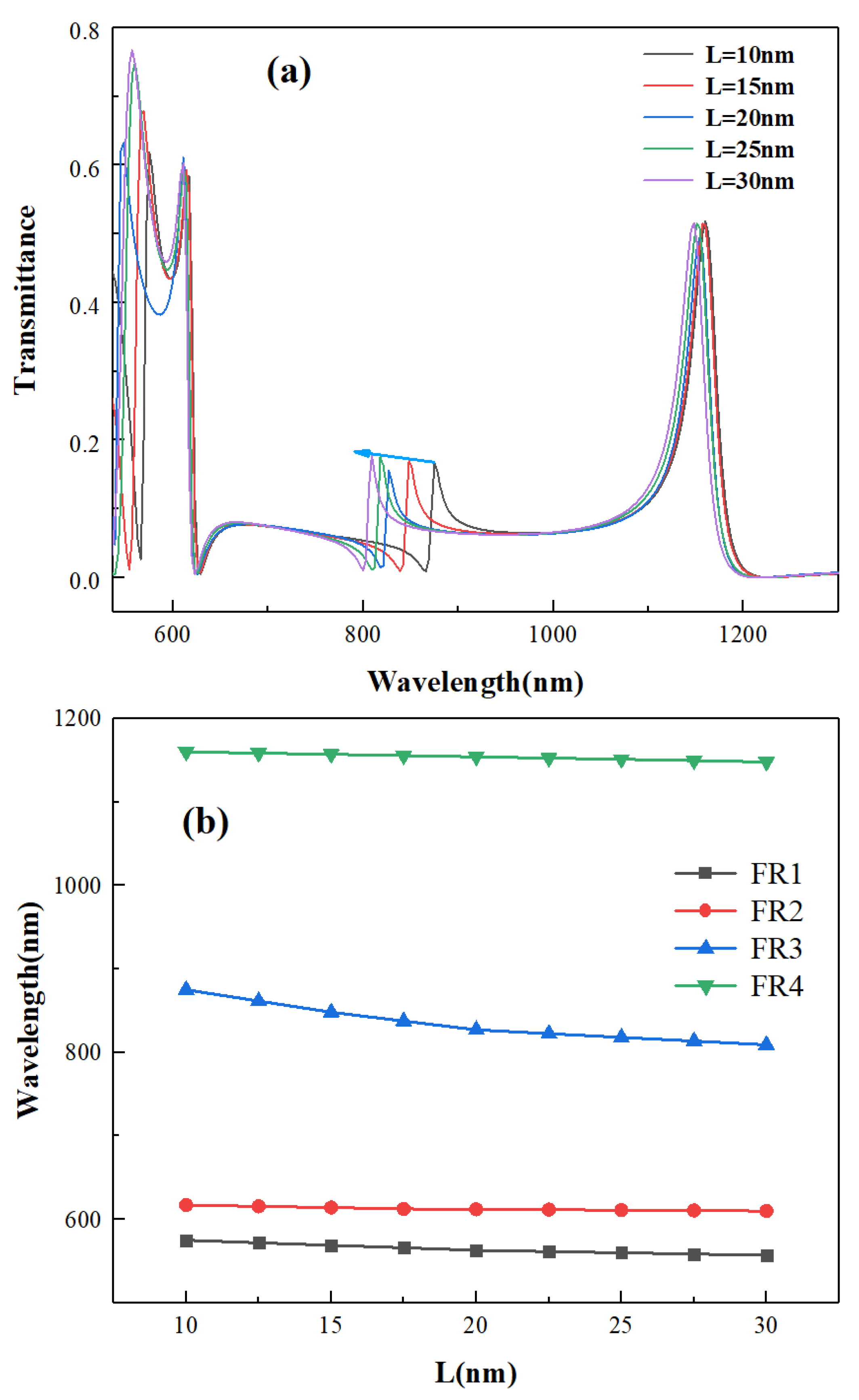
3. Results and Analysis
4. Conclusions
Author Contributions
Funding
Data Availability Statement
Acknowledgments
Conflicts of Interest
References
- Barnes, W.L.; Dereux, A.; Ebbesen, T.W. Surface plasmon subwavelength optics. Nature 2003, 424, 824–830. [Google Scholar] [CrossRef]
- Tao, J.; Huang, X.G.; Lin, X.; Zhang, Q.; Jin, X. A narrow-band subwavelength plasmonic waveguide filter with asymmetrical multiple-teeth-shaped structure. Opt. Express 2009, 17, 13989–13994. [Google Scholar] [CrossRef]
- Wahsheh, R.A.; Lu, Z.; Abushagur, M.A.G. Nanoplasmonic couplers and splitters. Opt. Express 2009, 17, 19033–19040. [Google Scholar] [CrossRef] [PubMed]
- Luk’Yanchuk, B.; Zheludev, N.; Maier, S.; Halas, N.; Nordlander, P.; Giessen, H.; Chong, C.T. The Fano resonance in plasmonic nanostructures and metamaterials. Nat. Mater. 2010, 9, 707–715. [Google Scholar] [CrossRef] [PubMed]
- Cai, D.-J.; Huang, Y.-H.; Wang, W.-J.; Ji, W.-B.; Chen, J.-D.; Chen, Z.-H.; Liu, S.-D. Fano Resonances Generated in a Single Dielectric Homogeneous Nanoparticle with High Structural Symmetry. J. Phys. Chem. C 2015, 119, 4252–4260. [Google Scholar] [CrossRef]
- Desrier, A.; Maquet, A.; Taïeb, R.; Caillat, J. Ionization dynamics through a Fano resonance: Time-domain interpretation of spectral amplitudes. Phys. Rev. A 2018, 98, 053406. [Google Scholar] [CrossRef] [Green Version]
- Jafari, O.; Shi, W.; LaRochelle, S. Efficiency-Speed Tradeoff in Slow-Light Silicon Photonic Modulators. IEEE J. Sel. Top. Quantum Electron. 2020, 27, 1–11. [Google Scholar] [CrossRef]
- Xie, Y.; Chai, J.; Ye, Y.; Song, T.; Liu, B.; Zhang, L.; Zhu, Y.; Liu, Y. A Tunable Slow Light Device with Multiple Channels Based on Plasmon-Induced Transparency. Plasmonics 2021, 16, 1–8. [Google Scholar] [CrossRef]
- Eroglu, Y.S.; Anjinappa, C.K.; Guvenc, I.; Pala, N. Slow Beam Steering and NOMA for Indoor Multi-User Visible Light Communications. IEEE Trans. Mob. Comput. 2019, 20, 1627–1641. [Google Scholar] [CrossRef]
- Kumari, S.; Kumar, A.; Medhekar, S. Slow light in rod type 2D photonic crystal waveguide comprising of cavity: Optimization and analysis. Optik 2021, 231, 166438. [Google Scholar] [CrossRef]
- Sumetsky, M. Fundamental limit of microresonator field uniformity and slow light enabled ultraprecise displacement metrology. Opt. Lett. 2021, 46, 1656–1659. [Google Scholar] [CrossRef] [PubMed]
- Hattori, S.; Moris, M.; Shinozaki, K.; Ishii, K.; Verbiest, T. Vortex-Induced Harmonic Light Scattering of Porphyrin J-Aggregates. J. Phys. Chem. B 2021, 125, 2690–2695. [Google Scholar] [CrossRef] [PubMed]
- Marinkovic, D.Z.; Medar, M.L.J.; Becin, A.P.; Andric, S.A.; Kostic, T.S. Growing Up Under Constant Light: A Challenge to the Endocrine Function of the Leydig Cells. Front. Endocrinol. 2021, 12, 653602. [Google Scholar] [CrossRef]
- Eyland, D.; van Wesemael, J.; Lawson, T.; Carpentier, S. The impact of slow stomatal kinetics on photosynthesis and water use efficiency under fluctuating light. Plant Physiol. 2021, 186, 998–1012. [Google Scholar] [CrossRef] [PubMed]
- Yu, Z.; Chouchene, B.; Liu, M.; Moussa, H.; Schneider, R.; Moliere, M.; Liao, H.; Chen, Y.; Sun, L. Influence of laminated architectures of heterostructured CeO2-ZnO and Fe2O3-ZnO films on photodegradation performances. Surf. Coat. Technol. 2020, 403, 126367. [Google Scholar] [CrossRef]
- Zhao, R.; Li, J.; Zhang, Q.; Liu, X.; Zhang, Y. Behavior of SPPs in chiral–graphene–chiral structure. Opt. Lett. 2021, 46, 1975–1978. [Google Scholar] [CrossRef]
- Moreira, R.; Wolfe, J.; Taylor, S.D. A high-yielding solid-phase total synthesis of daptomycin using a Fmoc SPPS stable kynurenine synthon. Org. Biomol. Chem. 2021, 19, 3144–3153. [Google Scholar] [CrossRef]
- Chen, X. Synthesis of multi-band filters based on multi-prototype transformation. IET Microw. Antennas Propagation 2020, 15, 103–114. [Google Scholar] [CrossRef]
- Dellweg, D.; Haidl, P.; Kerl, J.; Maurer, L.; Köhler, D. Bench testing of noninvasive ventilation masks with viral filters for the protection from inhalation of infectious respirable particles. J. Occup. Environ. Hyg. 2021, 18, 118–127. [Google Scholar] [CrossRef]
- Feng, C.; Ying, Z.; Zhao, Z.; Gu, J.; Pan, D.Z.; Chen, R.T. Wavelength-division-multiplexing (WDM)-based integrated electronic–photonic switching network (EPSN) for high-speed data processing and transportation. Nanophotonics 2020, 9, 4579–4588. [Google Scholar] [CrossRef]
- Nguyen, V.H.; Kim, I.K.; Seok, T.J. Silicon Photonic Mode-Division Reconfigurable Optical Add/Drop Multiplexers with Mode-Selective Integrated MEMS Switches. Photonics 2020, 7, 80. [Google Scholar] [CrossRef]
- Kang, S.; Zhang, R.; Hao, Z.; Jia, D.; Gao, F.; Bo, F.; Zhang, G.; Xu, J. High-efficiency chirped grating couplers on lithium niobate on insulator. Opt. Lett. 2020, 45, 6651–6654. [Google Scholar] [CrossRef] [PubMed]
- Liu, Y.; Huang, X.; Li, Z.; Guan, H.; Wei, Q.; Fan, Z.; Han, W.; Li, Z.-Y. Efficient grating couplers on a thin film lithium niobate–silicon rich nitride hybrid platform. Opt. Lett. 2020, 45, 6847–6850. [Google Scholar] [CrossRef] [PubMed]
- Huang, H.; Wu, Y.; Wang, W.; Feng, W.; Shi, Y. Analysis of the Propagation Constant of a Ridge Gap Waveguide and Its Application of Dual-Band Unequal Couplers. IEEE Trans. Plasma Sci. 2020, 48, 4163–4170. [Google Scholar] [CrossRef]
- Jin, H.; Chen, L.; Li, J.; An, X.; Wu, Y.; Zhu, L.; Yi, H.; Li, K.H. Vertically stacked RGB LEDs with optimized distributed Bragg reflectors. Opt. Lett. 2020, 45, 6671–6674. [Google Scholar] [CrossRef]
- Lohithakshan, L.C.; Geetha, V.; Kannan, P. Single polymer-variable index for the design and fabrication of variable stop band distributed Bragg reflectors. Opt. Mater. 2020, 110, 110509. [Google Scholar] [CrossRef]
- Wu, C.; Wei, W.; Yuan, X.; Zhang, Y.; Yan, X.; Zhang, X. Design and Simulation of Low-Threshold Miniaturized Single-Mode Nanowire Lasers Combined with a Photonic Crystal Microcavity and Asymmetric Distributed-Bragg-Reflector Mirrors. Nanomaterials 2020, 10, 2344. [Google Scholar] [CrossRef]
- Chen, Y.; Zhou, X.; Xu, Y.; Xiao, C.; Zhu, Q. Fano Resonance Sensing Based on Coupling ofSub-wavelength Grating and All-dielectric MultilayerFilm under Angle Modulation. Appl. Opt. 2021, 60, 2902–2906. [Google Scholar] [CrossRef]
- Nikoghosyan, H.; Manukyan, V.; Harutyunyan, S.; Nikoghosyan, G. Fano resonance model for the processes of photoionization of two-well heterostructures in a transverse electric field. Phys. E Low-Dimensional Syst. Nanostructures 2020, 128, 114587. [Google Scholar] [CrossRef]
- Chen, Y.; Zhang, M.; Cao, J.; Xiao, C.; Zhu, Q. Structure of Multiple Fano Resonances in Double-baffle MDM Waveguide Coupled Cascaded Square Cavity for Application of High Throughput Detection. Plasmonics 2021, 9, 1–10. [Google Scholar] [CrossRef]
- Kilic, S.C.; Kocaman, S. Highly Sensitive and Tunable Fano-Like Rod-Type Silicon Photonic Crystal Refractive Index Sensor. IEEE Sens. J. 2021, 21, 7551–7557. [Google Scholar] [CrossRef]
- Zhu, J.; Qin, Y.; Wang, G.; Zheng, K. Novel Crescent-Shaped Cavity Resonator Based on Fano Resonance Spectrum. Plasmonics 2021, 16, 1557–1565. [Google Scholar] [CrossRef]
- Tu, D.; Wu, Y.; Xie, J.; Zang, X.; Ding, L.; Chen, L. Switchable Fano Resonance Based on Cut-Induced Asymmetric Split-Ring Resonators with Dirac Semimetal Film. Plasmonics 2021, 16, 1405–1415. [Google Scholar] [CrossRef]
- Chau, Y.-F.C.; Chao, C.-T.C.; Huang, H.J.; Kumara, N.T.R.N.; Lim, C.M.; Chiang, H.-P. Ultra-High Refractive Index Sensing Structure Based on a Metal-Insulator-Metal Waveguide-Coupled T-Shape Cavity with Metal Nanorod Defects. Nanomaterials 2019, 9, 1433. [Google Scholar] [CrossRef] [Green Version]
- Guo, J.; Yang, X.; Wang, Y.; Wang, M.; Hua, E.; Yan, S. Refractive Index Nanosensor With Simple Structure Based on Fano Resonance. IEEE Photonics J. 2020, 12, 1–10. [Google Scholar] [CrossRef]
- Yang, Q.; Liu, X.; Guo, F.; Bai, H.; Zhang, B.; Li, X.; Tan, Y.; Zhang, Z. Multiple Fano resonance in MIM waveguide system with cross-shaped cavity. Optik 2020, 220, 165163. [Google Scholar] [CrossRef]
- Liu, X.; Li, J.; Chen, J.; Rohimah, S.; Tian, H.; Wang, J.; Siti, R.; Li, J. Fano resonance based on D-shaped waveguide structure and its application for human hemoglobin detection. Appl. Opt. 2020, 59, 6424–6430. [Google Scholar] [CrossRef] [PubMed]
- Chen, J.; Li, J.; Liu, X.; Rohimah, S.; Tian, H.; Qi, D. Fano resonance in a MIM waveguide with double symmetric rectangular stubs and its sensing characteristics. Opt. Commun. 2020, 482, 126563. [Google Scholar] [CrossRef]
- Butt, M.; Kaźmierczak, A.; Kazanskiy, N.; Khonina, S. Metal-Insulator-Metal Waveguide-Based Racetrack Integrated Circular Cavity for Refractive Index Sensing Application. Electronics 2021, 10, 1419. [Google Scholar] [CrossRef]
- Palizvan, P.; Olyaee, S.; Seifouri, M. An Optical MIM Pressure Sensor Based on a Double Square Ring Resonator. Photonic Sens. 2018, 8, 242–247. [Google Scholar] [CrossRef] [Green Version]
- Palizvan, P.; Olyaee, S.; Seifouri, M. High Sensitive Optical Pressure Sensor Using Nano-Scale Plasmonic Resonator and Metal-Insulator-Metal Waveguides. J. Nanoelectron. Optoelectron. 2018, 13, 1449–1453. [Google Scholar] [CrossRef]
- Palermo, G.; Rippa, M.; Conti, Y.; Vestri, A.; Castagna, R.; Fusco, G.; Suffredini, E.; Zhou, J.; Zyss, J.; De Luca, A.; et al. Plasmonic Metasurfaces Based on Pyramidal Nanoholes for High-Efficiency SERS Biosensing. ACS Appl. Mater. Interfaces 2021, 13, 43715–43725. [Google Scholar] [CrossRef] [PubMed]
- Shaltout, A.M.; Kim, J.; Boltasseva, A.; Shalaev, V.M.; Kildishev, A.V. Ultrathin and multicolour optical cavities with embedded metasurfaces. Nat. Commun. 2018, 9, 1–7. [Google Scholar] [CrossRef] [PubMed] [Green Version]
- Lio, G.E.; Ferraro, A.; Ritacco, T.; Aceti, D.M.; De, A.; Giocondo, M.; Caputo, R. Leveraging on ENZ Metamaterials to Achieve 2D and 3D Hyper-Resolution in Two-Photon Direct Laser Writing. Adv. Mater. 2021, 33, 2008644. [Google Scholar] [CrossRef]
- Lotfiani, A.; Mohseni, S.; Ghanaatshoar, M. High-sensitive optoelectronic SPR biosensor based on Fano resonance in the integrated MIM junction and optical layers. Opt. Commun. 2020, 477, 126323. [Google Scholar] [CrossRef]
- Chen, J.; Gan, F.; Wang, Y.; Li, G. Plasmonic Sensing and Modulation Based on Fano Resonances. Adv. Opt. Mater. 2018, 6, 1701152. [Google Scholar] [CrossRef]


| Parameter | Symbol | Quantity | Unit |
|---|---|---|---|
| Bus waveguide width | w | 50 | nm |
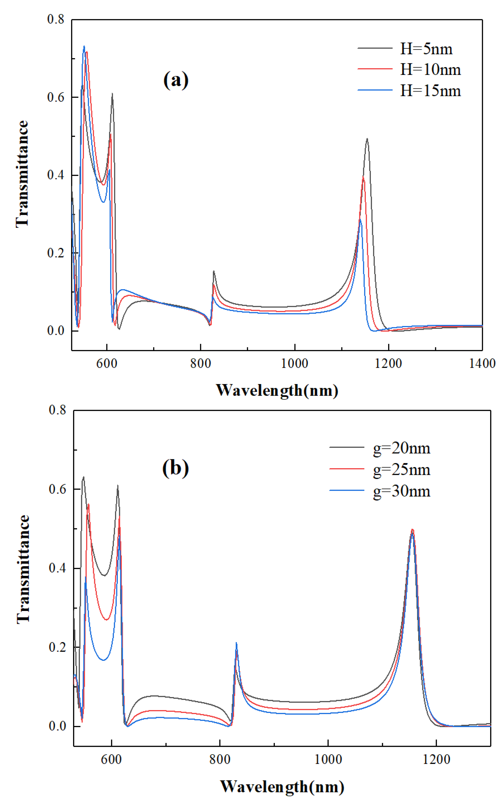
| Coupling gap height | H | 5 | nm |
| Split length | L | 20 | nm |
| Radius | R | 100 | nm |
| Silver baffle width | g | 20 | nm |
| Rectangular stubs height | h | 35 | nm |
| Rectangular stubs width | d | 30 | nm |
| Refractive index of bus waveguides | - | 1 | - |
| Refractive index of CSRRC | n | 1 | - |
| Waveguide Structure | Sensitivity | Reference |
|---|---|---|
| A groove and a ring resonator coupled with an MIM waveguide | 1160 nm/RIU | [11] |
| MIM waveguide structure consisting of an M-type cavity and a baffle | 780 nm/RIU | [13] |
| A half-ring resonator coupled MIM waveguide structure | 753 nm/RIU | [14] |
| An end-coupled ring-groove joint MIM waveguide structure | 1050 nm/RIU | [29] |
| MIM structure with one rectangular and two square nanorod array resonators | 1090 nm/RIU | [30] |
| MIM structure with two concentric double-square resonators | 1380 nm/RIU | [32] |
| A new racetrack integrated circular cavity based on MIM waveguide | 1400 nm/RIU | [40] |
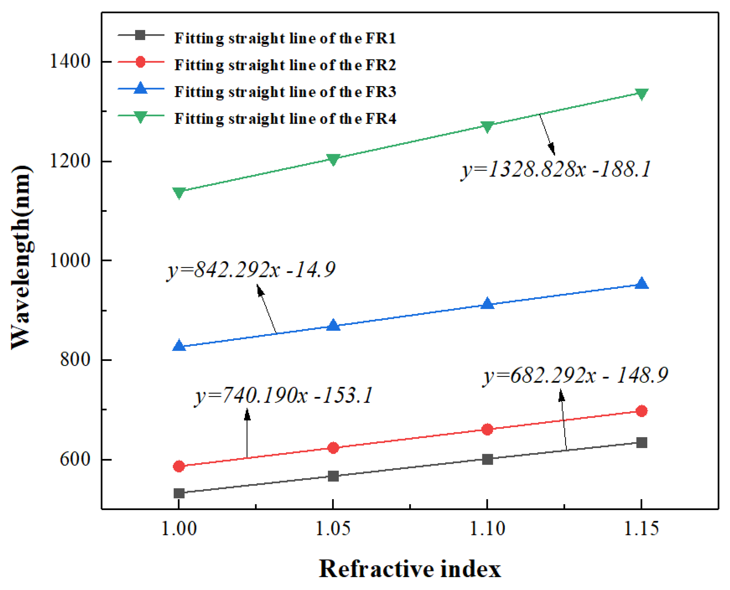
| This paper | 1328.8 nm/RIU |
Publisher’s Note: MDPI stays neutral with regard to jurisdictional claims in published maps and institutional affiliations. |
© 2021 by the authors. Licensee MDPI, Basel, Switzerland. This article is an open access article distributed under the terms and conditions of the Creative Commons Attribution (CC BY) license (https://creativecommons.org/licenses/by/4.0/).
Share and Cite
Chen, J.; Yang, H.; Fang, Z.; Zhao, M.; Xie, C. Refractive Index Sensing Based on Multiple Fano Resonances in a Split-Ring Cavity-Coupled MIM Waveguide. Photonics 2021, 8, 472. https://doi.org/10.3390/photonics8110472
Chen J, Yang H, Fang Z, Zhao M, Xie C. Refractive Index Sensing Based on Multiple Fano Resonances in a Split-Ring Cavity-Coupled MIM Waveguide. Photonics. 2021; 8(11):472. https://doi.org/10.3390/photonics8110472
Chicago/Turabian StyleChen, Jianfeng, Hao Yang, Zhiyuan Fang, Ming Zhao, and Chenbo Xie. 2021. "Refractive Index Sensing Based on Multiple Fano Resonances in a Split-Ring Cavity-Coupled MIM Waveguide" Photonics 8, no. 11: 472. https://doi.org/10.3390/photonics8110472