Article

Topological Charge and Asymptotic Phase Invariants of Vortex Laser Beams

by
Alexey A. Kovalev
1,2,
Victor V. Kotlyar
1,2 and
Anton G. Nalimov
1,2,*
1
Image Processing Systems Institute of RAS—Branch of the FSRC “Crystallography and Photonics” RAS, 151 Molodogvardeyskaya St., 443001 Samara, Russia
2
Technical Cybernetics Department, Samara National Research University, 34 Moskovskoe shosse, 443086 Samara, Russia
*
Author to whom correspondence should be addressed.
Photonics 2021, 8(10), 445; https://doi.org/10.3390/photonics8100445
Submission received: 17 September 2021 / Revised: 8 October 2021 / Accepted: 11 October 2021 / Published: 14 October 2021

Abstract

:
It is well known that the orbital angular momentum (OAM) of a light field is conserved on propagation. In this work, in contrast to the OAM, we analytically study conservation of the topological charge (TC), which is often confused with OAM, but has quite different physical meaning. To this end, we propose a huge-ring approximation of the Huygens–Fresnel principle, when the observation point is located on an infinite-radius ring. Based on this approximation, our proof of TC conservation reveals that there exist other quantities that are also propagation-invariant, and the number of these invariants is theoretically infinite. Numerical simulation confirms the conservation of two such invariants for two light fields. The results of this work can find applications in optical data transmission to identify optical signals.

1. Introduction

There are several well-known nondiffracting and propagation-invariant light fields. The most prominent examples in 3D space are Bessel beams [1], parabolic beams [2], and Mathieu beams [3], as well as the Laguerre–Gaussian and Hermite–Gaussian paraxial modes [4]. In 2D space, also known are the Airy and Weber beams [5,6]. Thorough reviews on propagation-invariant fields can be found in [7,8]. In addition to propagating in free space, the interaction of such beams with matter has been studied, including nonlinear processes [9]. Potential applications of such beams are, for example, wireless communications and optical interconnections. In addition to the beams that preserve their shape on propagation, there are several properties of the beam cross-section which are also propagation-invariant. These properties can be used as indicators that can help the receiver to identify the incoming signal beam. For instance, well-known such indicators are the orbital angular momentum (OAM) and the topological charge (TC) of vortex beams. Many studies have been dedicated to conservation of these properties, either on propagation in atmospheric turbulence [10] or after amplitude distortions [11]. Many studies sought to determine the OAM [12,13] or TC [14,15] of an optical signal beam.
These two indicators are often used interchangeably since, for conventional rotationally symmetric optical vortices, both OAM and TC give the same value. However, the nature of these indicators is quite different physically. While OAM is an integral property of a light field’s transverse intensity and phase distributions, which is calculated by integration over the whole transverse plane [16,17,18], TC is a purely phase property which is calculated by an integration of phase angular derivative over an infinite-radius circle [19] or closed curve. Thus, TC can be treated as an asymptotic phase property. Propagation invariance of the OAM can be easily proven mathematically since the propagation operator (Fresnel transform) is unitary. Conservation of both the OAM and the spin angular momentum on free-space propagation was proven in [20] (§4 “Eigenoperator description of laser beams”). Invariance of the TC cannot be proven in this way. This can be proven intuitively since it is known that phase singularities can disappear only as the result of annihilation of two singularities of opposite topological charge [21]. Thus, on propagation, TC should not change its value. However, there is a well-known study by Soskin et al., where a superposition of Gaussian and Laguerre–Gaussian beams with different waist radii could change the TC [22]. This seems to contradict the idea of TC conservation. Recently, we revisited this problem, studying the TC change on propagation of two different-waist LG beams [23] and showed that, when nearing the TC-change plane, certain vortices move away from the optical axis to infinity. Thus, the summary TC of all the vortices, including those in infinity, remains. Therefore, two questions arise: can the TC conservation be proven mathematically, and are there some other propagation-invariant asymptotic phase invariants of light fields?
In this paper, to prove that TC is conserved upon propagation, we introduce a huge-ring approximation, which is similar to the paraxial approximation; however, the distance from the optical axis is much larger than the propagation distance. Using this approximation, we prove that TC value does not change from one transverse plane to another. In addition, we show that other asymptotic phase propagation invariants can be constructed similarly to the TC.

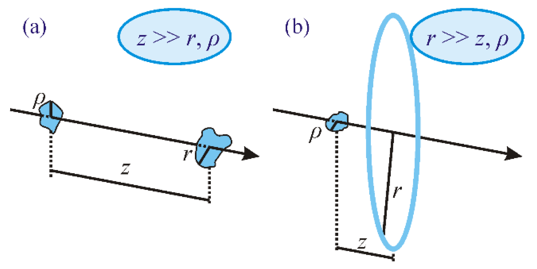
2. Orbital Angular Momentum and Topological Charge

If a light field propagates along the optical axis z and has the complex amplitude E(r, φ, z), where (r, φ, z) are the cylindrical coordinates, then its normalized OAM (OAM Jz divided by beam power W) in a transverse plane reads as follows [16,17,18]:
J z W = Im 0 0 2 π E * ( r , φ , z ) E ( r , φ , z ) φ r d r d φ 0 0 2 π E * ( r , φ , z ) E ( r , φ , z ) r d r d φ ,
where is the Planck constant (below we omit it for brevity), Im is the imaginary part of a complex number, and TC μ is defined as the integral over an infinite-radius circle [19].
μ = 1 2 π lim r 0 2 π φ [ arg E ( r , φ , z ) ] d φ .

3. Propagation of a Light Field in Free Space and Conservation of Its Orbital Angular Momentum

The complex amplitude of a monochromatic light field in homogeneous medium obeys the Helmholtz equation, which in the cylindrical coordinates reads as
2 E r 2 + 1 r E r + 1 r 2 2 E φ 2 + 2 E z 2 + k 2 E = 0 ,
where k = 2π/λ is the module of wavevector for light with the wavelength of λ. For paraxial propagation, the Helmholtz equation reduces to
2 i k E z + 2 E r 2 + 1 r E r + 1 r 2 2 E φ 2 = 0 .
It is well known that, if E is a solution of Equation (4), then the complex amplitude E(r, φ, z) in a transverse plane is related to that in the initial plane (z = 0) by the Fresnel transform [24].
E ( r , φ , z ) = i k 2 π z exp ( i k z + i k r 2 2 z ) × 0 0 2 π E ( ρ , θ , 0 ) exp [ i k ρ 2 2 z i k z r ρ cos ( θ φ ) ] ρ d ρ d θ .
It can be shown that the dot product of two functions is equal to the dot product of their Fresnel transforms. In addition, if E is a solution of Equation (4), then it is obvious that the functions E* and ∂E/∂φ are also solutions of Equation (4). Therefore, both the numerator and the denominator in Equation (1) are conserved on propagation; thus, the normalized OAM is also conserved. The detained proof of the OAM conservation can be found in [20] (§4 “Eigenoperator description of laser beams”).
As with nonparaxial free-space propagation, the OAM should be analyzed as a vectorial quantity. Its z-component reads as follows [25]:
J z = Im i = x , y , z 0 0 2 π E i * ( r , φ , z ) E i ( r , φ , z ) φ r d r d φ .
However, the quantity in Equation (1) (with E being an arbitrary transverse component of the electric strength vector—either Ex or Ey), albeit no longer describing the full z-component of the OAM, is also conserved on propagation. It can be proven tediously, but easily, using the plane wave expansion of a monochromatic nonparaxial light field.
E ( x , y , z ) = A ( α , β ) exp [ i k ( α x + β y + z 1 α 2 β 2 ) ] d α d β ,
where (x, y) are the Cartesian coordinates in a transverse plane, (α, β) are the Cartesian coordinates in the Fourier plane (cosines of the angles defining the directions of plane waves), and A(α, β) is the angular spectrum of plane waves.

4. Conservation of the Topological Charge

Unfortunately, conservation of TC (Equation (2)) cannot be proven so easily. According to the TC definition in Equation (2), the field should be analyzed in its periphery, at infinite distance r from the optical axis. Thus, paraxial approximation is inappropriate here. Therefore, we introduce another approximation, quite opposite to the paraxial. Generally, without the paraxial limits, if a light field propagates along the axis z, its complex amplitudes in two transverse planes (source plane and observation plane) are related by the Rayleigh–Sommerfeld integral [26].
E ( r , φ , z ) = 1 2 π 0 0 2 π E ( ρ , θ , 0 ) z [ exp ( i k L ) L ] ρ d ρ d θ ,
where L is the distance between a point in the source plane (ρ, θ, 0) and a point in the observation plane (r, φ, z).
L = [ z 2 + r 2 + ρ 2 2 r ρ cos ( θ φ ) ] 1 / 2 .
The complex amplitude given by Equation (8) is an exact solution of the Helmholtz equation and describes a light field without paraxial approximation.
The Fresnel transform in Equation (5) can be obtained from Equation (8) for a case when the propagation distance is large compared to the transverse coordinates (paraxial propagation) (Figure 1a); therefore,
L z + r 2 + ρ 2 2 r ρ cos ( θ φ ) 2 z .
To calculate the topological charge, we now suppose that, on the contrary, r is much greater than z and ρ (Figure 1b). Thus, the distance L is given by
L r + z 2 + ρ 2 2 r ρ cos ( θ φ ) .
We call this expression a huge-ring approximation. Using it, we obtain the complex amplitude on a very-large-radius ring in a transverse plane. The Rayleigh–Sommerfeld integral can be rewritten as
E ( r , φ , z ) = z 2 π 0 0 2 π E ( ρ , θ , 0 ) ( i k L 2 1 L 3 ) exp ( i k L ) ρ d ρ d θ .
Similarly to derivation of the Fresnel transform, we use Equation (11) for the exponent in the integrand, while the expression (ik/L2−1/L3) can be written approximately as ik/r2.
E ( r , φ , z ) = i k z 2 π r 2 exp ( i k r + i k z 2 2 r ) × 0 0 2 π E ( ρ , θ , 0 ) exp [ i k ρ 2 2 r i k ρ cos ( θ φ ) ] ρ d ρ d θ .
Equation (13) is the main equation in this work, and it allows us to estimate the complex amplitude on a circle of a very large radius, just as needed to calculate TC.
It is seen in Equation (13) that the integral is independent of z and depends only on the angular polar coordinate φ. On the contrary, the multipliers before the integrals are φ-independent. Therefore, the φ-derivative of the field phase (arg E)/∂φ is independent of z.
z [ lim r φ arg E ( r , φ , z ) ] = 0 .
Consequently, any quantities obtained from (arg E)/∂φ at large radii r are z-independent. The most prominent example is the topological charge of Equation (2). Thus, TC conservation is just a partial case following from Equation (14); below, we consider some other partial cases.

5. Asymptotic Phase Invariants of Vortex Laser Beams

Since the field should be continuous at φ = 0 and φ = 2π, arg E should change by an integer number of 2π, thus forcing TC to be an integer number. Even if it was fractional in the initial plane, on propagation, it becomes an integer [19]. However, Equation (14) indicates that, by using the function (arg E)/∂φ at large radii r, other propagation-invariant quantities may also be constructed, e.g.,
μ g = 1 2 π lim r 0 2 π g ( φ ) φ [ arg E ( r , φ , z ) ] d φ ,
were g(φ) is an arbitrary function.
To confirm our theory, we conducted some numerical experiments.
For constructing the invariants, we chose two functions: g1(φ) = cos φ and g2(φ) = rect(φ/π) (i.e., g2(φ) = 1 at –π/2 ≤ φ ≤ π/2 and g2(φ) = 0 otherwise). Accordingly, we tested whether or not the following values are asymptotic phase invariants:
μ 1 = 1 2 π lim r 0 2 π cos φ φ [ arg E ( r , φ , z ) ] d φ ,
μ 2 = 1 2 π lim r π / 2 π / 2 φ [ arg E ( r , φ , z ) ] d φ .
We note that, in general, the functions g(φ) and the argument of the complex amplitude (arg E) in Equation (15) are not analytic functions (for instance, g2(φ) in Equation (17) is not analytic). Therefore, the integral in Equation (15) cannot be evaluated by transforming to a contour integral in the complex plane and by using the theory of residues.

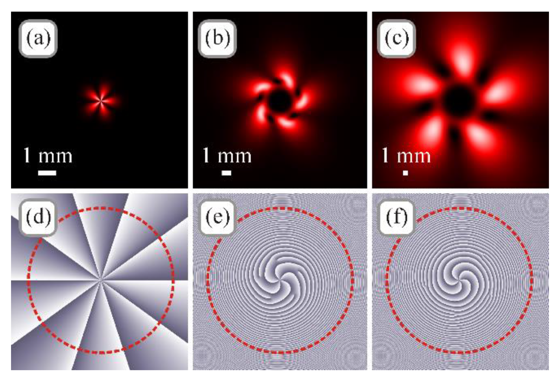
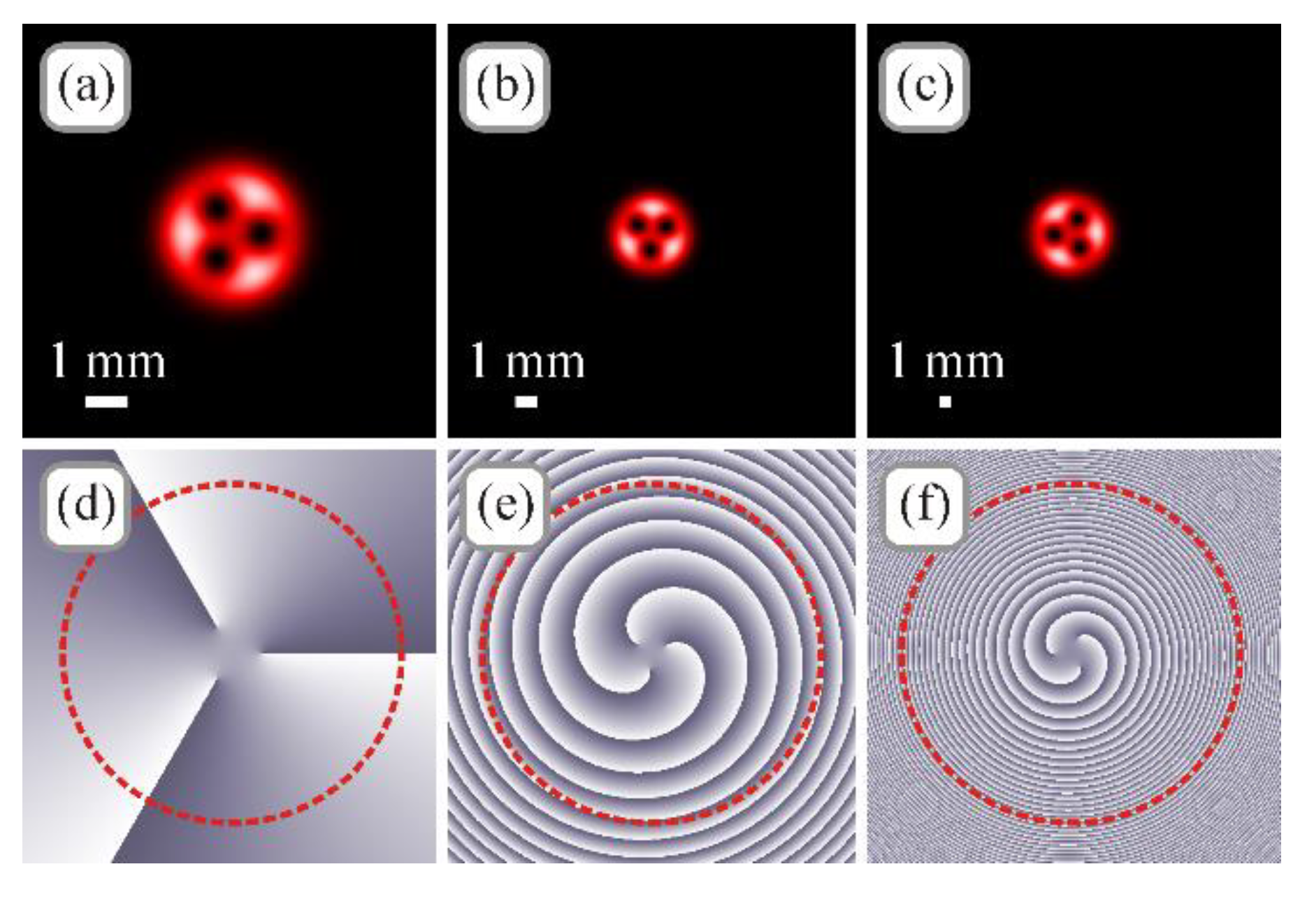
6. Numerical Simulation

The theory was obtained for the invariant quantities, computed over an infinite-radius circle. This is impractical, but it gives an idea that these quantities can also be conserved in other realistic conditions. Below, we consider two paraxial light beams, where we chose feasible simulation parameters quite opposite to the huge-ring approximation, i.e., when the circle radius is much smaller than the propagation distance.
For a test beam, we took a superposition of two Gaussian beams with optical vortices. In the initial plane (z = 0), such a beam has the following complex amplitude:
E ( r , φ , 0 ) = exp ( r 2 w 2 ) [ A 1 exp ( i n 1 φ ) + A 2 exp ( i n 2 φ ) ] ,
where w is the Gaussian beam waist radius, n1 and n2 are the topological charges of the vortices, and A1 and A2 are the superposition coefficients.
Figure 2 illustrates the intensity and phase distributions of the test beam from Equation (18) in several transverse planes for the following parameters: wavelength λ = 633 nm, waist radius w = 1 mm, topological charges n1 = 10 and n2 = 5, superposition coefficients A1 = 1 and A2 = 0.5, propagation distances z = 0 (initial plane), z = z0/2 (z0 = kw2/2 is the Rayleigh range), and z = 2 z0 (far field). The calculation area was −Rx, yR, with (x, y) being the Cartesian coordinates and R being the half-size of the area: R = 5 mm for z = 0, R = 10 mm for z = z0/2, and R = 20 mm for z = 2 z0. Red dashed lines on the phase distributions show the circles along which we calculated TC (Equation (2)) and the invariants (Equations (16) and (17)) (all circles were of radius 0.8 R). Figure 2a,d were obtained using Equation (18), whereas Figure 2b,c,e,f were obtained by using an expression for the Fresnel diffraction of a Gaussian optical vortex [27,28].
Calculation of TC using Equation (2) yielded nearly the same values for all three propagation distances: μ = 9.9999 at z = 0, μ = 9.9695 at z = z0/2, and at z = 2 z0 (the theoretical value of μ is 10 [13]). Calculation using Equation (16) yielded the value μ1 = −0.0015 for all three distances z. Calculation using Equation (17) yielded the value μ2 = 4.8514 at z = 0, μ2 = 4.9702 at z = z0/2, and μ2 = 4.9654 at z = 2 z0 (it is obvious that the theoretical value of μ2 should be 10/2 = 5).
As another test beam, we considered a Gaussian beam with multiple vortices located on a circle of a radius r0. Such a beam can be obtained as a coaxial superposition of a Laguerre–Gaussian vortex beam and of a Gaussian beam [29]. The complex amplitude of this beam reads as
E ( r , φ , z ) = 1 q exp ( r 2 q w 2 ) ( r m e i m φ q m r 0 m ) ,
where w is the Gaussian beam waist radius, m is the number of optical vortices with unit topological charge, and q = 1 + iz/z0.
Figure 3 depicts the intensity and phase distributions of the test beam from Equation (19) in several transverse planes for the following parameters: wavelength λ = 633 nm, waist radius w = 1 mm, number of vortices m = 3, radius of the circle with vortices r0 = 0.7 w, propagation distances z = 0, z = z0/2, and z = 2 z0, calculation area −Rx, yR with R = 5 mm for z = 0, R = 10 mm for z = z0/2, and R = 20 mm for z = 2 z0. Red dashed lines on the phase distributions show the circles along which we calculated TC (Equation (2)) and the invariants (Equations (16) and (17)) (all circles were of radius 0.8 R). All patterns in Figure 3 were obtained using Equation (19).
Calculation of TC using Equation (2) yielded μ = 3.0000 at z = 0, μ = 2.9996 at z = z0/2, and μ = 2.9941 at z = 2 z0 (the theoretical value of μ is 3). Calculation using Equation (16) yielded the value μ1 ≈ 0 (μ1 ≈ 10–4) for all three distances z. Calculation using Equation (17) yielded the value μ2 = 1.4980 at z = 0, μ2 = 1.4995 at z = z0/2, and μ2 = 1.4970 at z = 2 z0 (i.e., μ2 ≈ 1.5 in all transverse planes).
Thus, we note that, despite the above theory proving conservation of the TC and other asymptotic phase invariants, when they were calculated over an infinite-radius circle and when the light field propagated by a finite distance, the simulation, however, demonstrated that, in practice, for some specific light fields, these quantities can be conserved even when calculated over circles comparable to the beam transverse sizes and much smaller than the propagation distance. This indicates the potential of using these quantities for identifying incoming signals in optical wireless communications. It is hardly possible to estimate the necessary circle radius (R relative to z) for an arbitrary beam; however, in Figure 2 and Figure 3, this radius was about several times the effective beam width.

7. Conclusions

In conclusion, we suggested in this work an alternative way to prove the conservation of the topological charge of a light field on propagation. Our proof is based on a so-called huge-ring approximation of the Huygens–Fresnel principle, which is opposite to the paraxial approximation, and which we suggested here for the observation point on an infinite-radius ring. It turned out, that, in addition to the topological charge, phase distribution in areas far from the optical axis allows obtaining other quantities that are also propagation-invariant, and the number of these invariants is theoretically infinite. In simulation, we suggested two such invariants and tested them on two paraxial light fields. Of course, of practical interest are the invariants that are conserved on the rings of finite radii; in simulation, we also used finite-radius rings. However, there may exist light fields for which these invariants fail to be conserved. Thus, construction of the propagation-invariants using the condition in Equation (14), investigating their applicability to various light fields, and developing the methods for measuring these invariants, are aspects yet to be studied. The results of this work can find applications in optical data transmission. In a general case, for correctly measuring the TC of a nonsymmetric incoming optical signal, the phase distribution should be obtained, e.g., using the Shack–Hartmann wavefront sensor, as studied experimentally in [30,31]. Identifying an incoming beam using the invariants, such as the partial TC (Equation (17)), allows measuring the wavefront in a smaller area (rather than over the whole circle in the beam periphery).

Author Contributions

Conceptualization, A.A.K. and V.V.K.; methodology, A.A.K.; formal analysis, V.V.K.; software, A.G.N.; writing—original draft preparation, A.A.K. and A.G.N.; writing—review and editing, A.A.K., V.V.K. and A.G.N., supervision—V.V.K., funding acquisition—V.V.K. and A.A.K. All authors read and agreed to the published version of the manuscript.

Funding

The work was partly funded by the Russian Foundation for Basic Research under grant #18-29-20003 (Section 2 “Orbital angular momentum and topological charge”, Section 3 “Propagation of a light field in free space and conservation of its orbital angular momentum”, and Section 4 “Conservation of the topological charge”), the Russian Science Foundation under grant #18-19-00595 (Section 5 “Asymptotic phase invariants of vortex laser beams” and Section 6 “Numerical simulation”), and the RF Ministry of Science and Higher Education within a government project of the FSRC “Crystallography and Photonics” RAS (Section 1 “Introduction” and Section 7 “Conclusion”).

Institutional Review Board Statement

Not applicable.

Informed Consent Statement

Not applicable.

Conflicts of Interest

The authors declare no conflict of interest.

References

  1. Durnin, J.; Miceli, J.J.; Eberly, J.H. Diffraction-free beams. Phys. Rev. Lett. 1987, 58, 1499. [Google Scholar] [CrossRef]
  2. Bandres, M.; Gutiérrez-Vega, J.; Chávez-Cerda, S. Parabolic nondiffracting optical wave fields. Opt. Lett. 2004, 29, 44–46. [Google Scholar] [CrossRef] [PubMed]
  3. Gutiérrez-Vega, J.; Iturbe-Castillo, M.; Chávez-Cerda, S. Alternative formulation for invariant optical fields: Mathieu beams. Opt. Lett. 2000, 25, 1493–1495. [Google Scholar] [CrossRef]
  4. Siegman, A.E. Lasers; University Science: Mill Valley, CA, USA, 1986. [Google Scholar]
  5. Efremidis, N.; Chen, Z.; Segev, M.; Christodoulides, D. Airy beams and accelerating waves: An overview of recent advances. Optica 2019, 6, 686–701. [Google Scholar] [CrossRef] [Green Version]
  6. Zhang, P.; Hu, Y.; Li, T.; Cannan, D.; Yin, X.; Morandotti, R.; Chen, Z.; Zhang, X. Nonparaxial Mathieu and Weber Accelerating Beams. Phys. Rev. Lett. 2012, 109, 193901. [Google Scholar] [CrossRef] [Green Version]
  7. Turunen, J.; Friberg, A.T. Propagation-invariant optical fields. Prog. Opt. 2010, 54, 1–88. [Google Scholar]
  8. Levy, U.; Derevyanko, S.; Silberberg, Y. Light modes of free space. Prog. Opt. 2016, 61, 237–281. [Google Scholar]
  9. Xiong, H.; Huang, Y.; Wu, Y. Laguerre-Gaussian optical sum-sideband generation via orbital angular momentum exchange. Phys. Rev. A 2021, 103, 043506. [Google Scholar] [CrossRef]
  10. Gbur, G.; Tuson, R.K. Vortex beam propagation through atmospheric turbulence and topological charge conservation. J. Opt. Soc. Am. A 2008, 25, 225–230. [Google Scholar] [CrossRef] [PubMed]
  11. Volyar, A.V.; Bretsko, M.V.; Akimova, Y.E.; Egorov, Y.A.; Milyukov, V.V. Sectorial perturbation of vortex beams: Shannon entropy, orbital angular momentum and topological charge. Comput. Opt. 2019, 43, 723–734. [Google Scholar] [CrossRef]
  12. Alperin, S.N.; Niederriter, R.D.; Gopinath, J.T.; Siemens, M.E. Quantitative measurement of the orbital angular momentum of light with a single, stationary lens. Opt. Lett. 2016, 41, 5019–5022. [Google Scholar] [CrossRef]
  13. Kotlyar, V.V.; Kovalev, A.A.; Porfirev, A.P. Calculation of fractional orbital angular momentum of superpositions of optical vortices by intensity moments. Opt. Express 2019, 27, 11236–11251. [Google Scholar] [CrossRef]
  14. Melo, L.A.; Jesus-Silva, A.J.; Chávez-Cerda, S.; Ribeiro, P.H.S.; Soares, W.C. Direct measurement of the topological charge in elliptical beams using diffraction by a triangular aperture. Sci. Rep. 2018, 8, 6370. [Google Scholar] [CrossRef] [Green Version]
  15. Kotlyar, V.V.; Kovalev, A.A.; Porfirev, A.P. Astigmatic transforms of an optical vortex for measurement of its topological charge. Appl. Opt. 2017, 56, 4095–4104. [Google Scholar] [CrossRef]
  16. Allen, L.; Barnett, S.M.; Padgett, M.J. Orbital Angular Momentum; CRC Press: Boca Raton, FL, USA, 2003. [Google Scholar]
  17. Courtial, J.; Dholakia, K.; Allen, L.; Padgett, M.J. Gaussian beams with very high orbital angular momentum. Opt. Commun. 1997, 144, 210–213. [Google Scholar] [CrossRef]
  18. Martinez-Castellanos, I.; Gutiérrez-Vega, J. Shaping optical beams with non-integer orbital-angular momentum: A generalized differential operator approach. Opt. Lett. 2015, 40, 1764–1767. [Google Scholar] [CrossRef] [PubMed]
  19. Berry, M.V. Optical vortices evolving from helicoidal integer and fractional phase steps. J. Opt. A Pure Appl. Opt. 2004, 6, 259. [Google Scholar] [CrossRef]
  20. Allen, L.; Padgett, M.J.; Babiker, M., IV. The orbital angular momentum of light. Prog. Opt. 1999, 39, 291–372. [Google Scholar]
  21. Nye, J.F.; Berry, M.V. Dislocations in wave trains. Proc. R. Soc. Lond. Ser. A 1974, 336, 165–190. [Google Scholar]
  22. Soskin, M.S.; Gorshkov, V.N.; Vasnetsov, M.V.; Malos, J.T.; Heckenberg, N.R. Topological charge and angular momentum of light beams carrying optical vortices. Phys. Rev. A 1997, 56, 4064. [Google Scholar] [CrossRef] [Green Version]
  23. Kotlyar, V.V.; Kovalev, A.A.; Nalimov, A.G. Optical phase singularities ‘going to’infinity with a higher-than-light speed. J. Opt. 2021, 23, 105702. [Google Scholar] [CrossRef]
  24. Gori, F. Current Trends in Optics; Dainty, J.C., Ed.; Academic Press: Cambridge, MA, USA, 1994; p. 140. [Google Scholar]
  25. Humblet, J. Sur le moment d’impulsion d’une onde electromagnetique. Physica 1943, 10, 585–603. [Google Scholar] [CrossRef]
  26. Sommerfeld, A. Lectures on Theoretical Physics; Academic Press: New York, NY, USA, 1954; pp. 361–373. [Google Scholar]
  27. Sacks, Z.; Rozas, D.; Swartzlander, G.J. Holographic formation of optical-vortex filaments. Opt. Soc. Am. B 1998, 15, 2226–2234. [Google Scholar] [CrossRef]
  28. Kotlyar, V.V.; Kovalev, A.A.; Skidanov, R.V.; Moiseev, O.Y.; Soifer, V.A. Diffraction of a finite-radius plane wave and a Gaussian beam by a helical axicon and a spiral phase plate. J. Opt. Soc. Am. A 2007, 24, 1955–1964. [Google Scholar] [CrossRef]
  29. Dennis, M. Rows of optical vortices from elliptically perturbing a high-order beam. Opt. Lett. 2006, 31, 1325–1327. [Google Scholar] [CrossRef] [PubMed] [Green Version]
  30. Paroli, B.; Siano, M.; Potenza, M. Measuring the topological charge of orbital angular momentum radiation in single-shot by means of the wavefront intrinsic curvature. Appl. Opt. 2020, 59, 5258–5264. [Google Scholar] [CrossRef]
  31. Wang, D.; Huang, H.; Toyoda, H.; Liu, H. Topological Charge Detection Using Generalized Contour-Sum Method from Distorted Donut-Shaped Optical Vortex Beams: Experimental Comparison of Closed Path Determination Methods. Appl. Sci. 2019, 9, 3956. [Google Scholar] [CrossRef] [Green Version]
Figure 1. (a) Paraxial approximation: propagation distance z is much larger than transverse coordinates ρ and r in the input and output planes; (b) huge-ring approximation: transverse coordinate r in the output plane is much larger than the propagation distance z and the transverse coordinate ρ in the input plane.
Photonics 08 00445 g001
Figure 2. Intensity (ac) and phase (df) distributions of a superposition of two Gaussian vortices (Equation (18)) in several transverse planes for the following parameters: wavelength λ = 633 nm, waist radius w = 1 mm, topological charges n1 = 10 and n2 = 5, superposition coefficients A1 = 1 and A2 = 0.5, propagation distances z = 0 (a,d), z = z0/2 (b,e), and z = 2 z0 (c,f), calculation area −Rx, yR with R = 5 mm (a,d), R = 10 mm (b,e), and R = 20 mm (c,f). Red circles on the phase distributions are those along which TC (Equation (2)) and invariants (Equations (16) and (17)) were calculated.
Photonics 08 00445 g002
Figure 3. Intensity (ac) and phase (df) distributions of a Gaussian beam with several vortices (Equation (19)) in several transverse planes for the following parameters: wavelength λ = 633 nm, waist radius w = 1 mm, number of vortices m = 3, radius of the circle with vortices r0 = 0.7 w, propagation distances z = 0 (a,d), z = z0/2 (b,e), and z = 2 z0 (c,f), calculation area −Rx, yR with R = 5 mm (a,d), R = 10 mm (b,e), and R = 20 mm (c,f). Red circles on the phase distributions are those along which TC (Equation (2)) and invariants (Equations (16) and (17)) were calculated.
Photonics 08 00445 g003
Publisher’s Note: MDPI stays neutral with regard to jurisdictional claims in published maps and institutional affiliations.

