1. Introduction
In recent years, the R&D of fiber-optic gas sensors has been boosted by the growing demand of a variety of scientific and industrial applications in a wide spectrum of fields [
1,
2]. For example, detection of explosive/flammable gases and poisonous gases is of great importance in mining and petroleum industry [
3,
4]; selective sensing of volatile organic biomarkers exhaled from breath could provide useful information for clinical diagnosis of lung or gastric cancers [
5]; moreover, monitoring of the gaseous concentration and pressure is also essential for optimizing working condition of high-power gaseous laser systems. Compared to fiber-optic refractometers for measuring the refractive index of aqueous analytes, fiber-based gas refractometers generally need to be more sensitive, as variations in the refractive index of gaseous samples are typically in a narrow range between 10
−4 and 10
−6 refractive index unit (RIU). Besides, due to the large mismatch between the index of gaseous analytes (
ngas ~ 1) and optical fibers
(nsilica ~ 1.5), only a limited fraction of the evanescent field of the fiber-guided modes could penetrate into the gas samples, which constitutes a substantial challenge to enhance the sensitivity. Therefore, sensors based on hollow core fibers or open resonant cavities, in which the fraction of light-matter overlap is almost 100%, is frequently used.
A great number of fiber-based gas sensors adopt an interferometer sensing configuration featuring high sensitivities [
6,
7,
8,
9]. Among these sensors, Fabry–Pérot (F-P) fiber interferometers are extensively studied due to their small footprint, straightforward sensing mechanism, and relatively high sensitivities. F-P fiber sensors generally operate by measuring the changes in optical path difference induced by the refractive index variations of the gaseous samples in the F-P cavity. Fabrication of F-P fiber gas sensors could be realized by coating a polymer diaphragm on the tip of a single mode fiber (SMF) [
7,
9], splicing hollow core fibers between two SMFs [
10,
11], or cascading SMF with multiple hollow core fibers with different diameters [
12,
13]. Sensitivity of these sensors is typically on the order of 10
3 nm/RIU (refractive index unit). Particularly, Y. Yang et al. and M. Quan et al. proposed respectively in-line fiber sensing structures in which multiple F-P cavities were cascaded to enable Vernier effect [
8,
12]. Sensitivities of these two sensors were as high as 11,368 nm/RIU and 30,899 nm/RIU, respectively. Though the above-mentioned F-P sensors achieved relatively high sensitivities, their fabrications could be technically complicated, as fs-laser micromachining and tricky fiber splicing with meticulous position manipulation may be needed. Besides, the use of the state-of-the-art spectrum analyzer also considerably increases the cost of the sensing system.
Another interferometric sensing scenario that is frequently used is based on Mach–Zehnder (M-Z) scheme [
14,
15,
16,
17,
18]. For instance, K. Nazeri et al. demonstrated a M-Z gas index sensor fabricated by immobilizing a segment of hollow-core photonic crystal fiber (HC-PCF) between two SMFs with airgaps at each side [
14]. The sensitivity of 4629 nm/RIU was reported for a sensor using a 3.3 mm-long HC-PCF. Z. Shao et al. proposed to sandwich a segment of six-air-hole PCF between two SMFs with a slight offset splicing at the lead-in junction [
15]. The sensor operated by measuring the amplitude variations in the transmission spectrum in response to changes in gas refractive index. The sensor resolution was calculated as 1.2 × 10
−6 RIU. Moreover, N. Zhang et al. demonstrated a gas refractometer based on a tapered optical microfiber M-Z interferometer working at the dispersion turning point (DTP) [
16]. Experimental results showed that an ultrahigh sensitivity of ~69,984 nm/RIU was achieved. We note that these sensors used expensive PCFs with tricky splicing process or fragile microfibers, which brought complexity to the fabrication and operation of the sensor. Moreover, these sensors also need to use costly spectrum analyzers.
Some fiber-optic directional couplers could be potentially used as gas index sensors due to their ultrahigh sensitivities for refractive index sensing [
19,
20,
21]. These sensors are typically developed using microstructured dual-core fibers (MDFs), in which the dual cores are spatially close. Therefore, guided modes would couple back-and-forth between the dual cores, thus creating the so-called even/odd super-modes. Interference between the even and odd super-modes could be affected by changes in the index of gaseous samples filling the microstructures, thus shifting the transmission spectrum. O. Bang et al. theoretically proposed that the sensitivity of a fiber directional coupler could be as high as 70,000 nm/RIU for refractometric applications [
21]. However, fabrication of MDFs is somewhat technically challenging, and infiltration of gas samples into the micron-sized (or submicron-sized) holes in the holey structures also requires a relatively long time.
Aside from these fiber sensors, gas refractometers may also be realized by using in-fiber resonant structures such as fiber gratings or fiber-based surface plasmon resonance structures [
22,
23,
24]. These sensors generally had sensitivities on the order of 10
3 nm/RIU. However, fabricating the resonant structures in fibers generally used sophisticated phase-mask lithographic techniques and/or required deposition of metallic layers with precise nanometer-scale thickness.
Finally, we also note that the gas refractometers introduced above may also be used for detection of certain specific gaseous analytes by coating functionalized polymer layers on the sensing head of the fiber sensors. Refractive index of the functionalized polymer layers which are able to selectively absorb or adsorb targeted gas molecules could be altered by varying concentration of the gaseous analytes. Thus, by interrogating the sensor response resulted from the index variations of the coated polymer layers, one could characterize the variations in concentration of the gaseous analytes. The gaseous analytes which could be interrogated may include CO
2, NH
3, and formaldehyde, to name a few [
3,
9,
25].
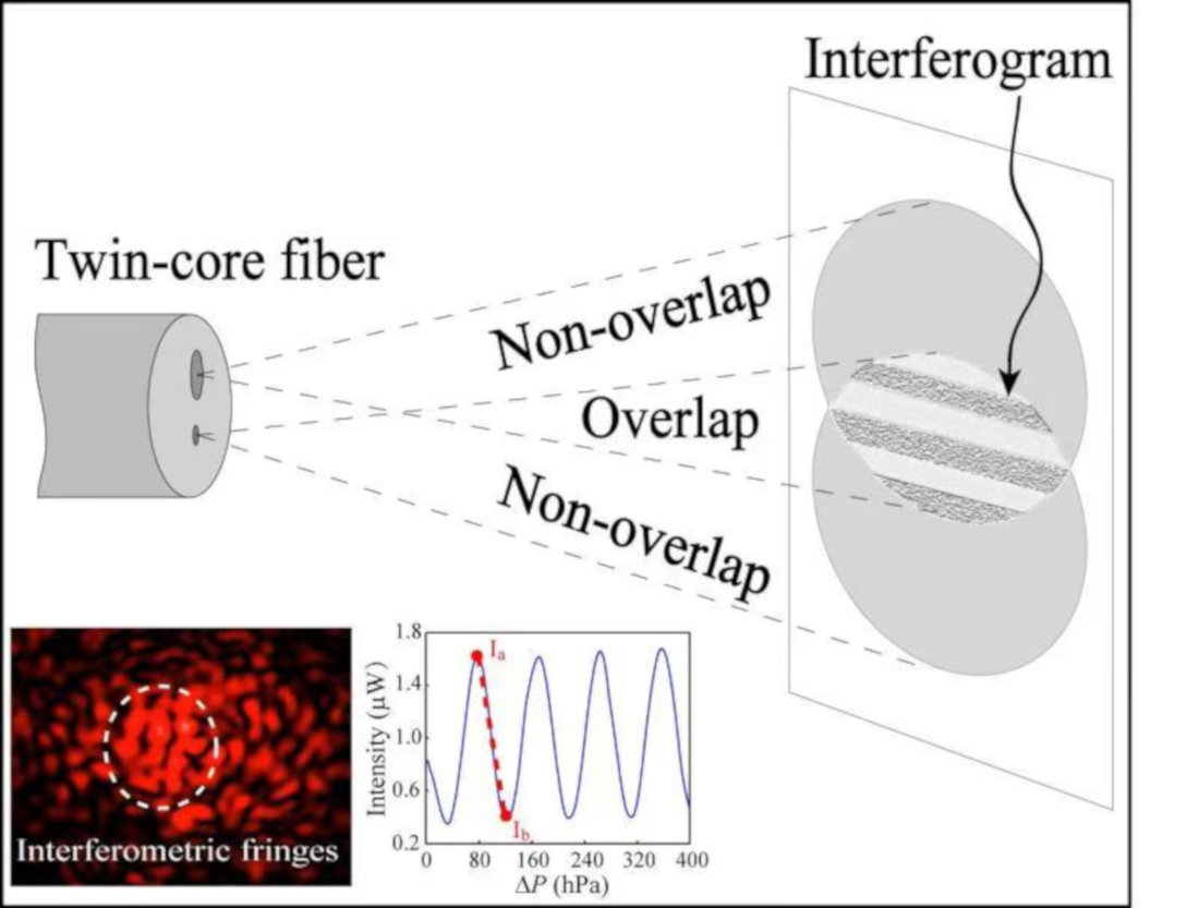
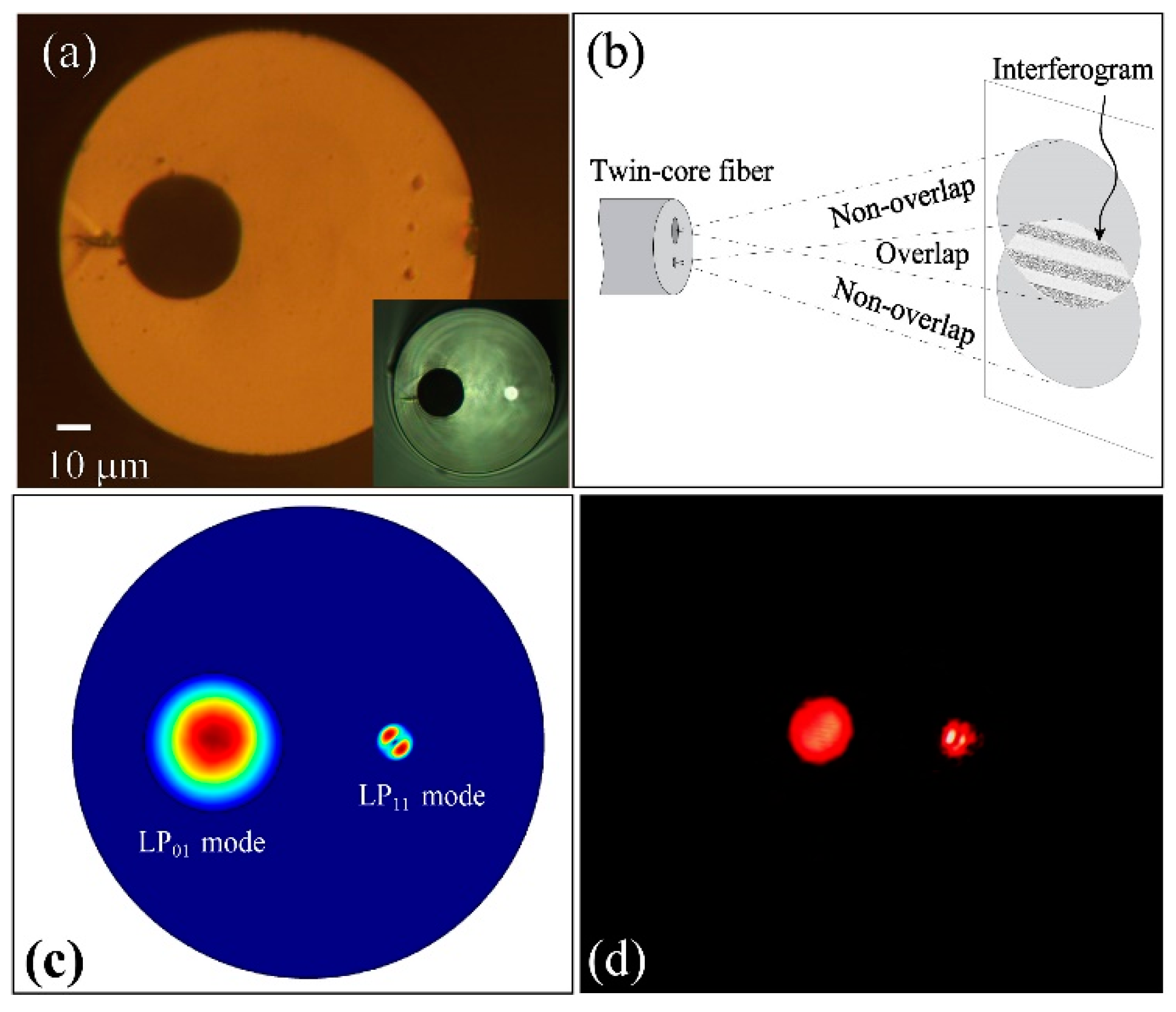
In this paper, we propose and experimentally demonstrate an ultrasensitive Mach–Zehnder (M-Z) gas refractometer based on a dual-core fiber (DCF). As shown in
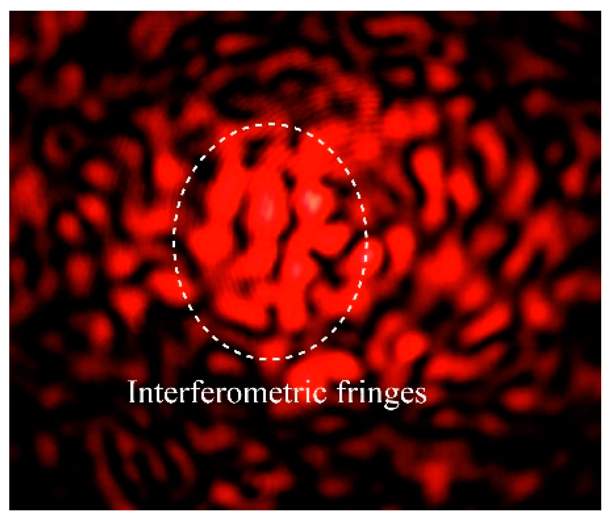
Figure 1a, this DCF has an eccentric Ge-doped silica core and relatively large air core running along the entire fiber. A He-Ne laser beam is split into two virtually parallel beams which are coupled to the dual cores, respectively. The light transmitted by the dual cores would produce an interferogram at the output end of the fiber. As the refractive index of the air channel filled with gaseous samples changes, the effective index of the guided modes guided in the air channel is accordingly modified, thus resulting in spatial shifts of the interference fringes. By correlating the number of fringe-shifts to the variations in the index of the gaseous analyte filled in the air channel, we could characterize the performance of the sensor. Moreover, we can also replace the camera by a photodiode detector together with a slit to monitor the amplitude changes during the fringe shifts. Experimental results suggest that the sensor proposed has a resolution as high as 10
−8 RIU. Similar to the fiber directional couplers mentioned above, the sensor proposed here is also based on DCFs. However, the sensing mechanism of our sensor is completely different from that of fiber directional couples in which even and odd super-modes are excited. The fundamental reason is that in this DCF the modes excited in the hollow core have effective refractive indices substantially mismatched with that of the modes guided in the solid core. Therefore, super-modes could not be excited, even when the two cores are spatially close with each other. Compared to the fiber gas sensors that involved tricky fiber post-processing and the state-of-the-art spectrum analyzers, we find our sensors advantageous for its straightforward sensing scheme, ease of manufacturing, cost-effectiveness, and high resolution. The sensor reported in this paper has strong potential for applications where ultrasensitive detection of gas refractive index and precise air-pressure monitoring are relevant.
3. Operation Principle of the Sensor
The sensing mechanism of the DCF sensor could be simply described as follows. When coherent laser beams are coupled to the two cores, guided modes in the two cores are excited and propagate independently. Transmitted light from the two cores would partially overlap and produce an interferogram. Variations in the refractive index of gaseous samples filling the hollow core would change the phase difference,
, of the light propagating two cores as
where
is the change in the refractive index of the air channel;
l is the length of the fiber;
is wavenumber defined as
, where
is the operating wavelength in vacuum. Experimentally, variations in the index of the air channel would cause the fringe shifts in the interferogram. Therefore, we could characterize the sensor by correlating the fringe shifts to the refractive index of the detected gaseous samples filling the air channel. A single fringe shift corresponds to 2
variation of
. Therefore, we could define the sensitivity,
S, of the sensor as the first-order derivative of fringe-shift number (
) to the refractive-index variation of the gas sample as shown in Equation (2)
According to Equation (2), sensitivity of the sensor is linearly proportional to length of the fiber and inversely proportional to the wavelength of the laser source. Thus, a higher sensitivity could be obtained by using a longer piece of DCF or a laser source of smaller wavelengths. However, note that the laser source should have a coherent length greater than , where is the refractive index of the Ge-doped silica core, such that the transmitted light from the dual cores could interfere. In this work, we choose He-Ne laser (632.8 nm) due to its readily availability, stable output power, and long coherent length.
As an alternative method to characterize the sensor, we could apply a fast Fourier transform (FFT) to the fringe shifts (recorded in consecutive images or videos), and then calculate the phase shift in the Fourier domain. The changes in the refractive index of gaseous sample would be directly correlated to the variations in phase. However, processing videos of interferogram with FFT algorithm is generally time-consuming, especially when high-frame-rate videos are involved. Thus, this route is not suitable for real-time monitoring of gas refractive index or air pressure.
4. Experimental and Numerical Results
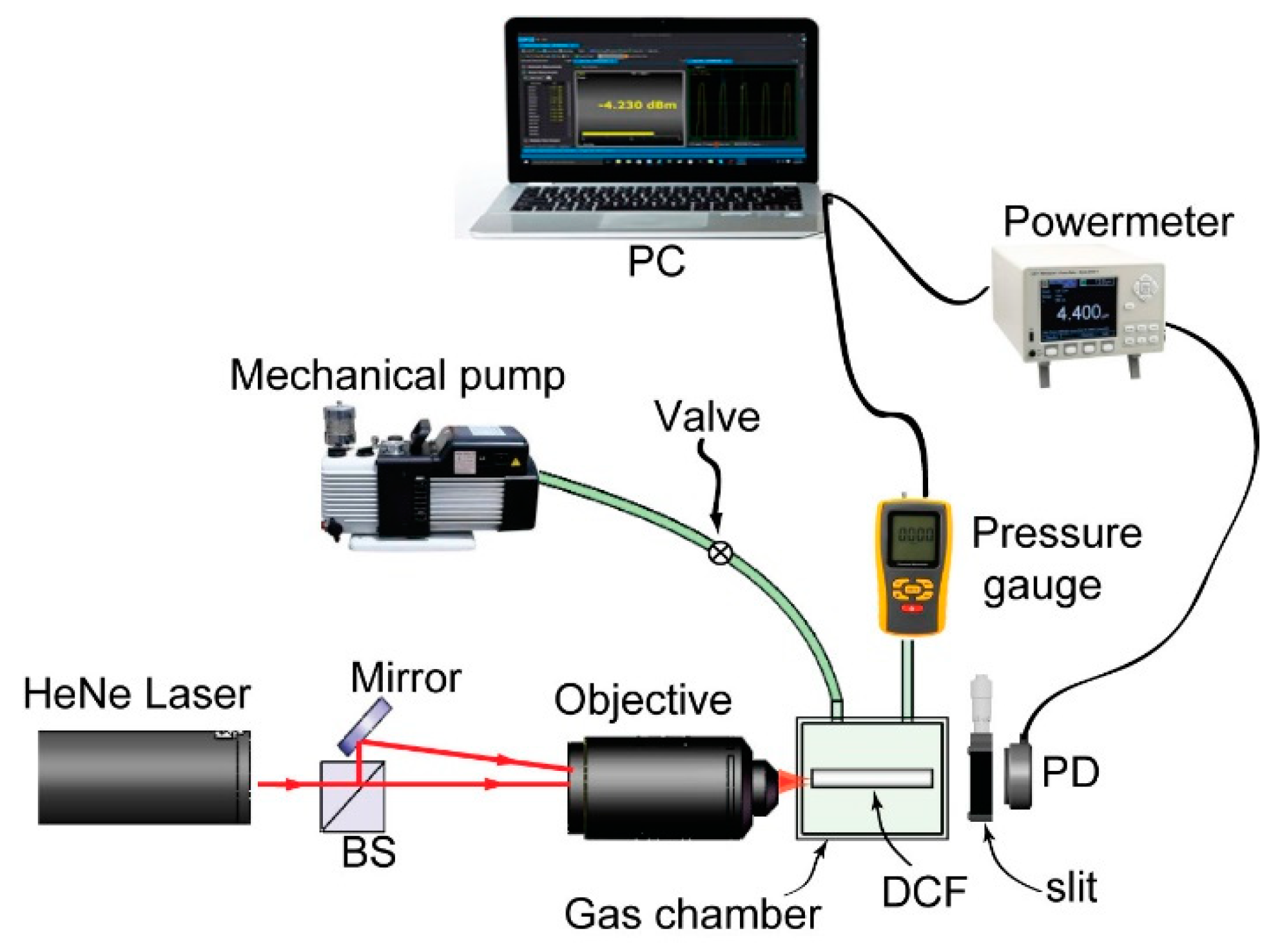
In
Figure 2, we show schematic of the proposed DCF sensor. A He-Ne laser (HNL020LB, Thorlabs, 1 mW) with a wavelength of 632.8 nm is split into two beams by a beam splitter. Using a 20× microscopic objective, one beam is coupled directly into the air channel of the fiber, while the other beam is firstly reflected by a mirror to propagate virtually parallel to its counterpart and then coupled into the solid core by the same objective. To visualize the guided modes of the DCF, we use another 20× microscopic objective to project the output image onto a CMOS camera as shown in
Figure 1d. For the wavelength of 632.8 nm, both the air channel and the solid core would support multimode guidance. Experimentally, in the hollow core, we observe a LP
01-mode-dominated multimoded field distribution. In the solid core, we observe a LP
11-dominated multimoded field distribution. No crosstalk between the two modes are experimentally found. We also use finite element method (COMSOL 5.0) to simulate these two modes (
Figure 1c). The effective indices of these two modes are virtually identical to the indices of the air defined by Equation (3) and index of the solid Ge-doped silica core (
nsc ~ 1.457), respectively. The discrepancy between the effective indices of the guided modes and the material (i.e., air and Ge-doped silica) indices is smaller than the software precision that is set as 10
−12 RIU. The COMSOL simulation results also suggest that the effective indices of the guides modes in the dual cores are virtually independent to the wavelength as well as the diameters of the dual cores, when the diameters of air core and solid core are more than 20 μm and 9 μm, respectively.
For gas sensing applications, we directly placed a CMOS camera behind the DCF. Therefore, the transmitted light from the two cores would interfere, and thus produce an interferogram that is then captured by the camera. Note that to further lower the cost of the system, the CMOS camera could be replaced by a webcam. Experimentally, a ~2.5 cm-long DCF is sealed into in an air-tight gas chamber. Transparent windows attached on the chamber allow convenient optical coupling of laser beams into the fiber. A mechanical vacuum pump is connected to the chamber to regulate the inner air pressure which is continuously monitored by a digital vacuum gauge with a resolution of 1 hPa (10
2 Pa). The correlation between the pressure and refractive index of air could be approximated as [
12]
where
P is the absolute air pressure (Pa), and
T is temperature (°C). Thus, under a constant temperature, refractive index of the air is linearly proportional to the air pressure. Note that changes in refractive index of the fiber materials (fused silica) due to pressure variations are neglected, since the pressure-optic coefficient of silica is two orders smaller than that of the air [
27]. Experimentally, we first pump out the air in the chamber to lower the internal air pressure to 100 hPa. Then, the mechanical pump is shut down to let air back flow to the chamber until the inner pressure of the chamber elevates up to the atmosphere pressure, 1018.0 hPa. During this period, we log the air pressure of the chamber using a pressure gauge (VC-9200, Lutron Inc), and simultaneously the fringe shifts in the interferogram are recorded using a CMOS camera (
Figure 3).
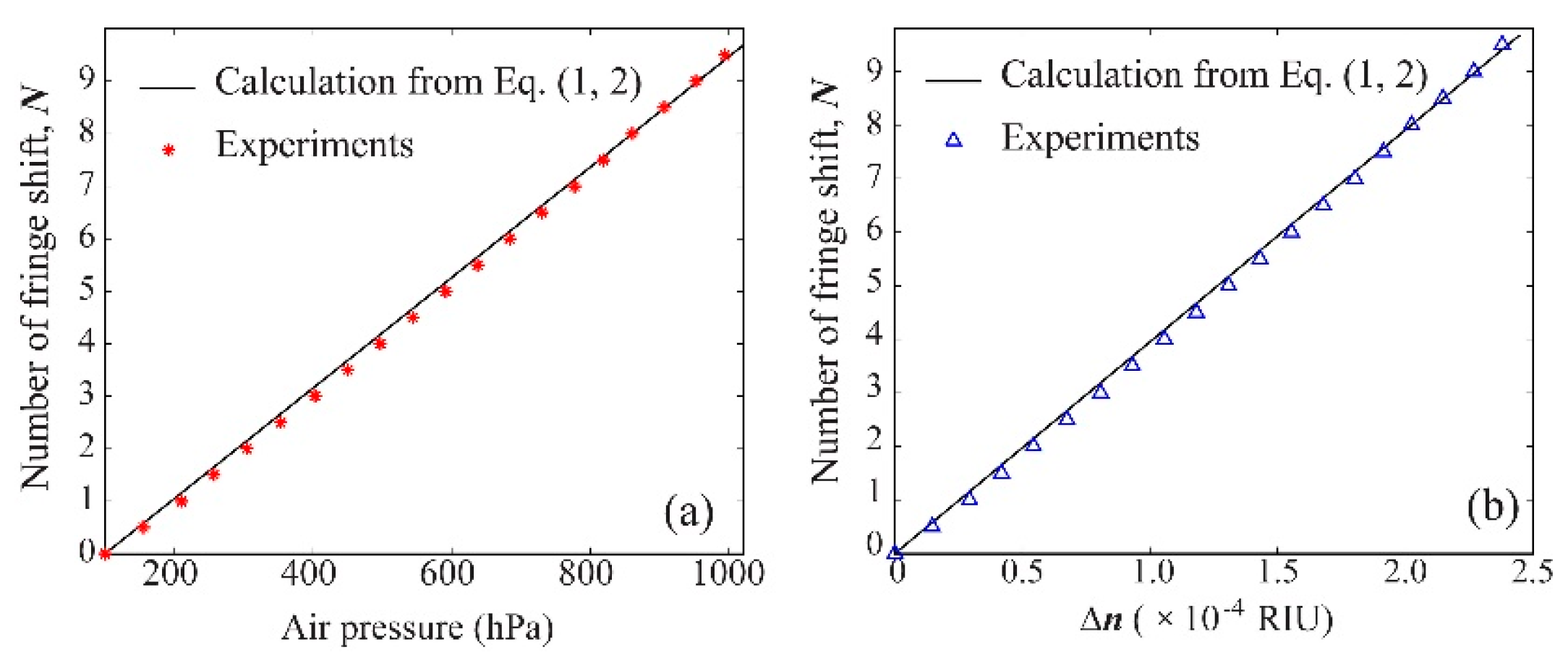
We count the fringe shifts (see
Video S1 in Supplementary) as a function of air pressure and the corresponding refractive index (calculated using Equation (3)) of the air filling the air channel, respectively, as shown in
Figure 4. Thus, the experimental sensitivity of the sensor (DCF length: ~2.5 cm) could be defined as number of fringe shifts per refractive index unit (RIU) and is found to be ~3.98 × 10
4/RIU. Note that the sensitivity of the sensor is linearly proportional to the length of the fiber according to Equation (2), and thus higher sensitivities of the sensor could be obtained by using longer fibers. However, the guided modes in the air channel are leaky modes, which have relatively high propagation loss as compared to the modes guided in the solid core. Using the cut-back technique, we measure the loss,
of the light guided in the hollow core to be ~ 0.5 dB/cm, and its counterpart of the light guided in the solid core could be virtually neglected (
) for short-distance (<1 m) propagation.
Consequently, increasing length of the DCF would cause imbalance of the output power from the two cores, and thus diminish visibility of the interference fringes. Here, the fringe visibility is defined by
where
is the maximum intensity in a bright stripe in the interferogram, and
is the minimal intensity in a dark stripe. Based on theory of optical interference, the intensity,
I, in the interferogram has the following approximate correlation with the output power of the two cores.
where
and
are the output power from the two cores, respectively. According to Equation (5),
I would have its maxima,
, or minima,
, when
equals to an even or odd multiple of π, respectively. Assuming that the in-coupled power for either core is identical and equals to
Pin, we could associate the fringe visibility,
f, with the length,
l, of the fiber as well as propagation loss,
of the light guiding in the hollow core as
Equation (6) suggests that increasing length of the DCF would degrade the fringe visibility. Therefore, a tradeoff on the fiber length has to be made to ensure a qualified visibility. We assume that the fringe shifts could reliably distinguished when f is greater than 0.5. Therefore, according to Equation (6), the maximum length of the DCF is limited to ~23 cm.
In
Figure 4, we also present the theoretical fringe shifts calculated using Equation (1,2), in which the temperature T = 25 °C (laboratory temperature) and
l = 2.5 cm. The theoretical predictions agree quite well with the experimental results. In
Figure 4b, we note that the refractive index of the gas in the air channel features an almost perfect linear response to the fringe shifts counted. Thus, assuming a primitive electronic circuit that resolves only a change from the maximum to the minimum of the fringe intensity (0.5 fringe shift) is used, the detection limit of the sensor would be ~1.21 × 10
−5 RIU. In fact, almost three orders of resolution improvement could be gained by analyzing full intensity curves as shown in the following discussion.
In a practical air refractive index sensor, instead of using an expensive CCD or COMS camera, we could use a single photodiode together with a slit to register the optical intensity of a small area in the interferogram. The width of the slit should be adjusted to be comparable to (or slightly narrower than) that of a single bright or dark stripe in the interference fringes. To do that, we first put a camera behind the DCF to capture the output image, and then insert a slit between the DCF and the camera. By adjusting the width of the slit, only a single stripe in the interference fringes could pass through the slit and then get recorded by the camera. Experimentally, the slit has a length of 0.5 mm and a width of 0.2 mm, and the distance between the output end of the DCF and the slit is ~3.5 cm. Finally, we replace the camera with a photodiode detector (S150C, Thorlabs) to register the intensity variations resulted from the fringe shifts.
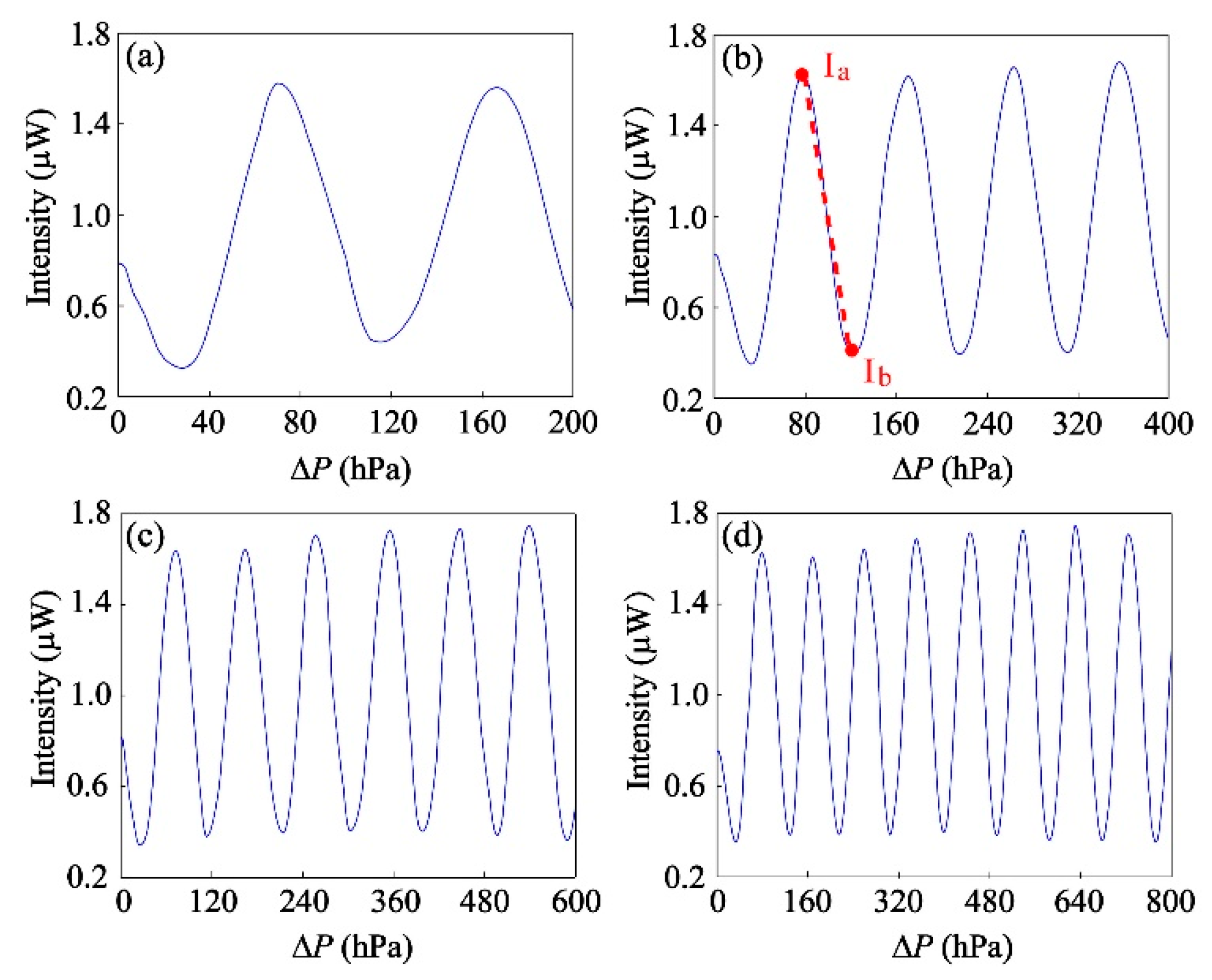
In
Figure 5, we show the intensity variations measured by the photodiode, while the air pressure inside the gas chamber changes from 100 to 300, 500, 700, and 900 hPa, respectively. The intensity oscillations are a direct consequence of the spatial fringe shifts as a result of the changes of the air pressure and thus the refractive index of the air channel. Therefore, via counting the number of the periods of the intensity variation, we could also quantify the corresponding changes in the refractive index of gas samples filling the air channel of the DCF. Note that there is also a good repeatability of the sensor. Particularly, the results in
Figure 5a–c look simply like cutouts of
Figure 5d, although these four measurements are completely independent.
As mentioned earlier, analysis on intensity variations may provide a much higher sensitivity. For instance, in
Figure 5b we could approximately apply a linear fitting between maximum (
Ia) and minimum (
Ib) on the second falling edge that corresponds to air pressure variation of 45.0 hPa, and thus a refractive index variation of 1.20 × 10
−5 RIU according to Equation (2). Here, the intensity difference between
Ia and
Ib is ~1.22 μW. To calculate the resolution of the sensor, we need to measure the experimental noise of the sensor. Thus, we maintain the inner pressure of the gas chamber at a constant value and measure the root-mean-square (RMS) intensity fluctuation of the output signal. Experimentally, the fluctuation is found to be ~0.1% of the registered intensity. We conclude that this noise is mainly attributed to the intensity fluctuation (also 0.1%) of the He-Ne laser. To put this noise level into perspective, we could assume the minimally detectable change in the optical intensity to be 0.1% of the average registered intensity shown in
Figure 5, which is ~1 nW. Thus, we estimate the resolution of our sensor to be ~1 × 10
−8 RIU for gas index sensing. Such a resolution is comparable to the highest resolution that was reported in previous literature [
11]. Finally, since this sensing scenario is based on intensity-interrogation modality, experimental noises such as ambient light (less than 100 pW) and light-source fluctuation would degrade the measured signals. While these noises cannot be completely eliminated, they could be substantially minimized by (1) optically isolating the senor head from the ambient environment, (2) using a lock-in amplifier and a chopper to filter out ambient-light noise, and/or (3) synchronically measuring the intensity of the light source (as a reference signal) as well as the sensor output signal, and then normalizing the sensor output with respect to the reference signal.


 ,
, 


