Article

Evaluation of Nanoplasmonic Optical Fiber Sensors Based on D-Type and Suspended Core Fibers with Metallic Nanowires

by
Diego Santos
1,2,
Ariel Guerreiro
3,4 and
José Manuel Baptista
2,4,*
1
Institute for Plasmas and Nuclear Fusion, Av. Rovisco Pais 1, 1049-0001 Lisboa, Portugal
2
Faculty of Exact Sciences and Engineering, University of Madeira, Campus da Penteada, 9020-105 Funchal, Portugal
3
Department of Physics and Astronomy, Faculty of Sciences, University of Porto, R. Campo Alegre, 4169-007 Porto, Portugal
4
INESC TEC—Center of Applied Photonics, R. Campo Alegre, 4169-007 Porto, Portugal
*
Author to whom correspondence should be addressed.
Photonics 2019, 6(3), 100; https://doi.org/10.3390/photonics6030100
Submission received: 26 July 2019 / Revised: 7 September 2019 / Accepted: 9 September 2019 / Published: 13 September 2019

Abstract

:
The introduction of metallic nanostructures in optical fibers has revolutionized the field of plasmonic sensors since they produce sharper and fine-tuned resonances resulting in higher sensitivities and resolutions. This article evaluates the performance of three different plasmonic optical fiber sensors based on D-type and suspended core fibers with metallic nanowires. It addresses how their different materials, geometry of the components, and their relative position can influence the coupling between the localized plasmonic modes and the guided optical mode. It also evaluates how that affects the spatial distributions of optical power of the different modes and consequently their overlap and coupling, which ultimately impacts the sensor performance. In this work, we use numerical simulations based on finite element methods to validate the importance of tailoring the features of the guided optical mode to promote an enhanced coupling with the localized modes. The results in terms of sensitivity and resolution demonstrate the advantages of using suspended core fibers with metallic nanowires.

1. Introduction

Using nanostructures such as metallic nanowires permits the generation of localized plasmonic effects that present very thin spectral widths, a feature that is fundamental to achieve high refractive index sensitivities and extremely low resolution values. For that, tailoring sensing structures design is of the utmost relevance to achieve higher performances. Thus, the goal is to customize the design of the sensing structure to optimize the coupling between the fundamental guided core mode with localized plasmonic wire modes. This kind of sensing structure has the capacity to enhance the sensitivity and resolution to external refractive index changes, and to simultaneously measure other important parameters like temperature, allowing correct refractive index measurements, independent of temperature cross effects [1,2,3].
Previous research work of the authors has been oriented to comprehend the effects of optical fiber sensing structural geometries in guided mode properties [4,5,6]. Different metal thicknesses, different materials, and different optical fiber geometries have been also tested in order to optimize the interaction between the guided mode and the plasmonic modes. For instance, diverse metallic elements have been also experimented, such as conventional metallic layers, artificial metamaterial layers [7,8,9,10,11], and more recently, nanowires [12,13,14,15], with the objective of improving and tailoring the properties of the plasmonic modes, such as spectral width, magnitude, and wavelength.
When using an optical D-type fiber, the fundamental guided mode is strongly confined in the core and does not excite the localized plasmonic modes of the metallic nanowire mounted on the top of the flat surface. On the other hand, the light guided in a suspended core fiber is not confined to a well-defined circular domain. In fact, light extends over the silica central area to produce a stronger excitation of the plasmonic modes in the metallic nanowire.
Therefore, in this work we investigate the use of a suspended core optical fiber structure in conjunction with a metallic nanowire and compare it with a conventional D-type optical fiber structure with a metallic nanowire. To increase the scope of the analysis, we investigate two different D-type optical fibers. One more conventional, with a germanium doped silica core and a fluor doped silica cladding, and a second one with an undoped silica core and a fluor doped silica cladding fiber. The material properties of this second D-type optical fiber are closer to those of the suspended core optical fiber. The work is based on simulation models using the finite element method (FEM) and is performed in COMSOL Multiphysics [4,5,6]. The article addresses how the material and geometrical parameters of the two types of optical fibers, with a metallic nanowire, can be customized to optimize the plasmonic effects and ultimately enhance the sensitivity and resolution to the refractive index of the external medium.

2. Materials and Methods

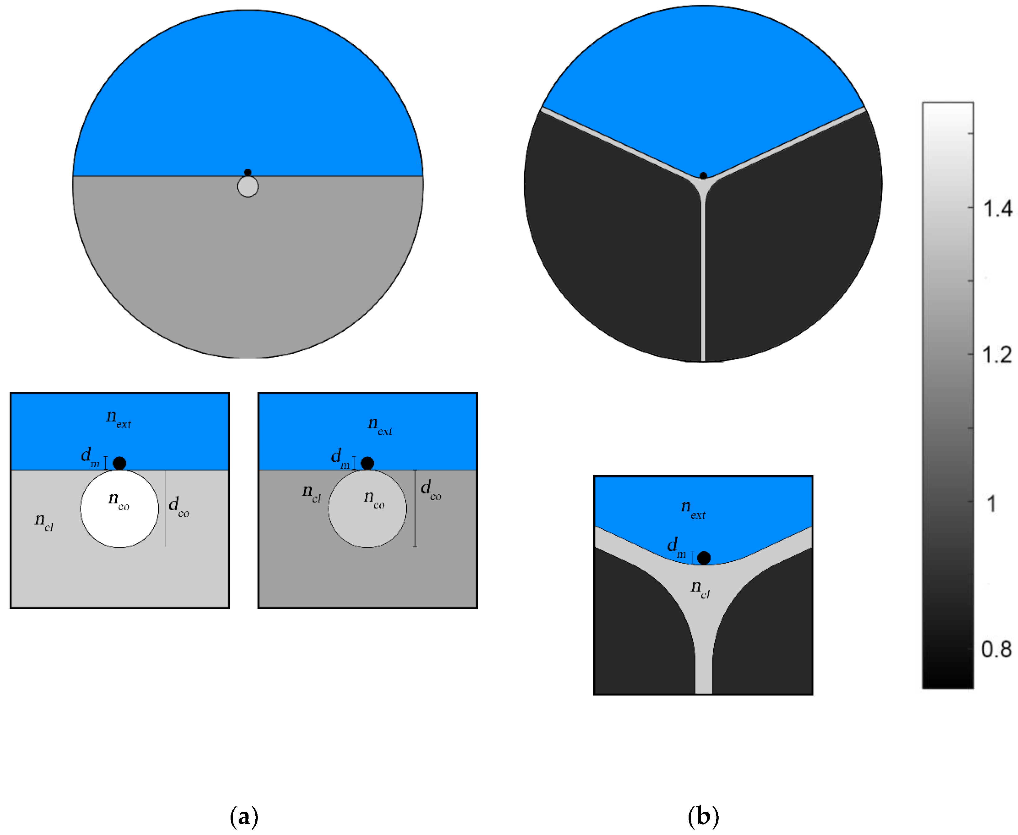
We consider three optical fiber sensing structures for refractive index measurement. Two of the sensing structures are based on a D-type fiber profile with a gold wire positioned on the flat surface, being one of them with a silica core doped with germanium (16%) and a silica cladding doped with fluor (3%), and the other with a pure silica core and a silica cladding doped with fluor (3%). The diameter of the core is 3200 nm and the diameter of the metallic wire is 600 nm.
The third optical fiber sensing structure for refractive index is based on a suspended core fiber with a core of undoped silica. Approximately one third of the cladding (the upper part) is filled with external refractive index to be measured, and the other two thirds are filled with air. The suspended core fiber capillaries form an angle of 120° between them and have a thickness of 800 nm. The gold wire is placed at the upper external side of the junction of three suspensions and is exposed to the external refractive index. The offset of the gold nanowire to the center of the fiber is 1400 nm, being the core curvature 5000 nm. Figure 1 illustrates the two designs. “In this case, only one of the holes of the suspend core fiber is exposed to the external refractive index [16].”
The refractive indexes of the undoped and doped silica materials were calculated using the Sellmeier equation [6]. For the calculation of the refractive index of the gold wire the Drude equation was used [17]. The space above the core of the fibers is filled with a medium characterized by the so called external refractive index, denoted as next and represented in blue in Figure 1.
It is possible to characterize the optical properties of the fundamental and localized modes, in the core and in the metallic nanowires respectively, in terms of their dispersion curves. Their intersection corresponds to the optimal conditions for the coupling between the fundamental mode of the core and the localized plasmonic modes of the metallic nanowire, forming the supermodes [18,19]. It is possible to numerically compute all these modes by resolving the wave equation for the electric field Fourier components,
× [ × E ( r , ω ) k 0 2 ε ˜ r ( r , ω ) ] E ( r , ω )
where E(r,ω) is the electric field and the term ε ˜ r denotes the complex relative dielectric function, written as the real part (nr) and the imaginary part (nr’’) of the refractive index. k0 = ω/c is the field mode wave-number, being ω the angular frequency and c the light speed.
Loss is one of the study parameters of the simulation analysis and it is described in decibels as
α d B = 10 ln ( 10 ) α L ,
where α = 2nefk0 is the power absorption coefficient and L is the interaction length of the sensor (1 mm). Other parameters examined are sensitivity (S) and resolution (R), which are calculated as [7]:
S ( λ ) = Δ λ p e a k Δ n e x t
R ( λ ) = 1 S ( λ ) Δ λ min = Δ n e x t Δ λ min Δ λ p e a k
where Δλpeak is the shift in wavelength of the resonance peak obtained from the simulation analysis for different external refractive indexes (next) and λmin is the minimum wavelength value between two spectral lines that can be detected experimentally.

3. Results and Discussion

In this section, we analyze the real and imaginary part of the refractive index (RI) of the three sensors in terms of the features of the resonance peaks corresponding to the supermodes. We also analyze the loss spectrum and compare the performance of the three sensor configurations in terms of sensitivity and resolution.
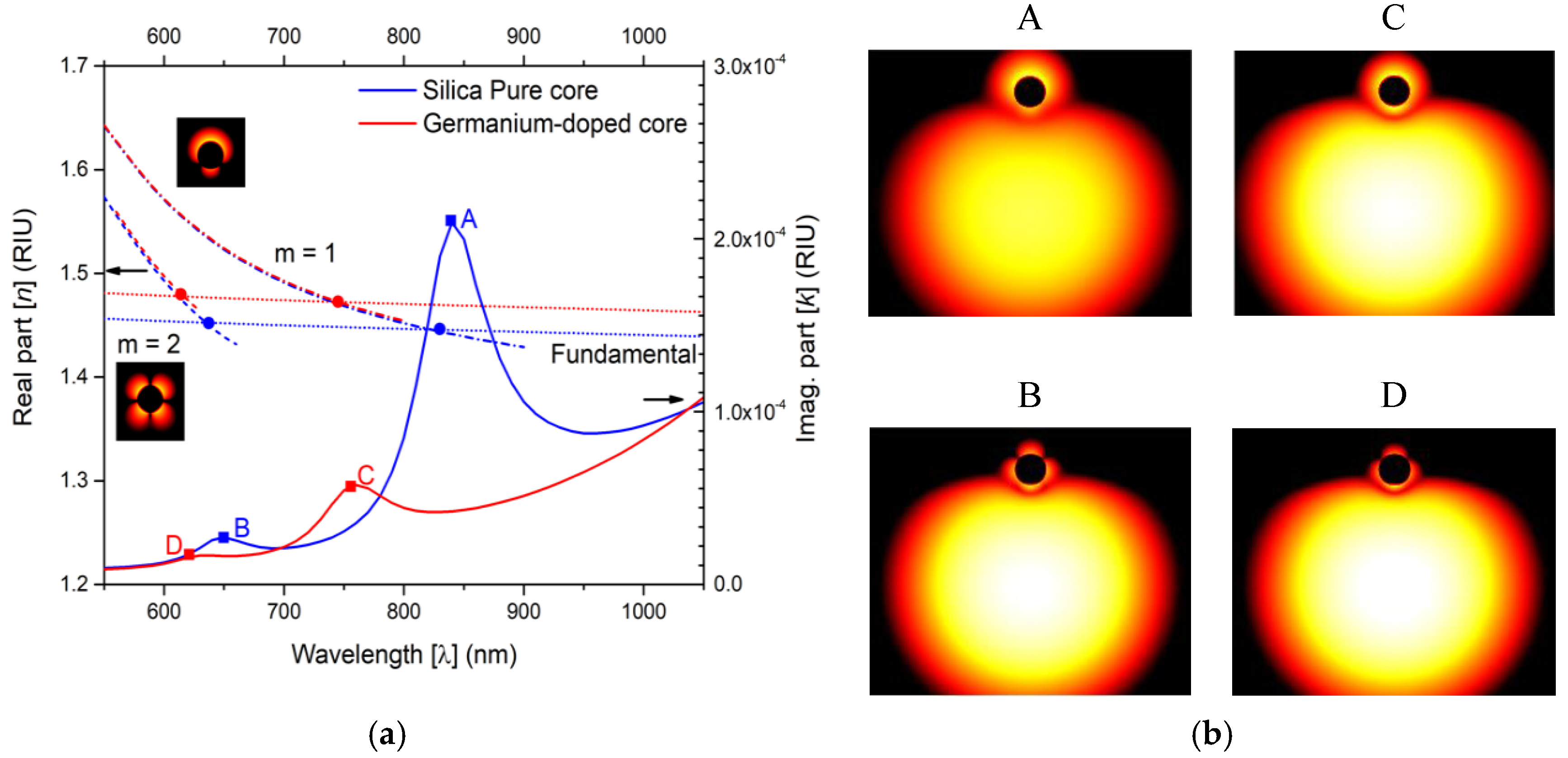
Figure 2a presents RI real part of the plasmon modes of the nanowire (m = 1, 2) for an external refractive index of 1.36 and of the fundamental modes of the two D-type optical fibers for an external refractive index of 1.36. Figure 2a shows also the imaginary part of the RI of the sensors. All curves are as function of wavelength, for a range between 550–1050 nm. The crossing between the dispersion curves (curves of the fundamental modes of the fibers and curves of the metal nanowire modes, m = 1 and m = 2) are specified by the circular dots and whose frequencies match those of the peaks, indicated by the squared dots in the RI imaginary part curve, which demonstrates resonate couplings. Therefore, we are in the presence of four phase-matching points (the circular dots of Figure 2a), and four resonance peaks (the squared dots of Figure 2a), that indicate the occurrence of the four supermodes (A–D).
In the inset of Figure 2a are shown the detailed light intensity distributions of the metallic nanowire plasmon modes taken isolated, namely for m = 1, 2, respectively. Figure 2b images illustrate the detailed light intensity distribution in the cores of the fibers and in the respective metal wires for supermodes A–D, for the two D-type fiber sensing structures. As it can be seen by images of Figure 2b, the mode hybridization alters the light distribution, but it maintains the plasmon modes dipolar (supermodes A and C) and quadrupole characteristics (supermodes B and C), respectively [18]. In this article, we will focus our attention on supermode A of the pure silica D-type fiber and supermode C of the germanium doped core of the D-type fiber, since they present stronger loss peaks, which is potentially better for sensing in terms of sensitivity and resolution.
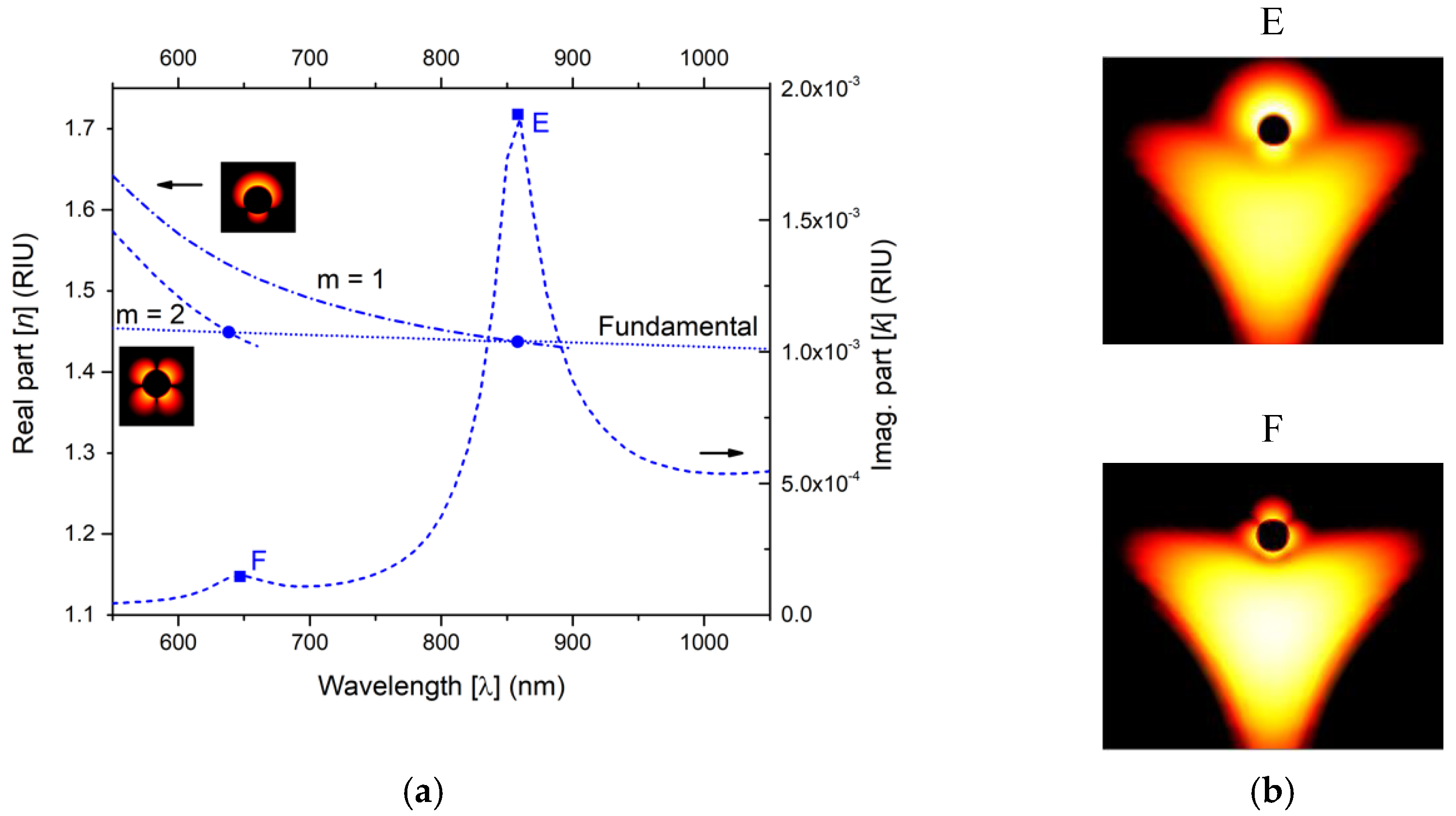
Turning our attention to the suspended core fiber and performing the same type of analysis, Figure 3a illustrates the RI real part of the plasmon modes of the nanowire (m = 1, 2) and of the fundamental modes of the suspended core optical fiber for an external refractive index of 1.36. Figure 3a presents also the RI imaginary part for the suspended core fiber sensing structure. All curves are as function of wavelength, for a range between 550–1050 nm. Again, the crossing between dispersion curves (curves of the fundamental mode of the fiber and curves of the metal nanowire modes, m = 1 and m = 2) are specified by the circular dots and whose frequencies match those of the peaks, indicated by the squared dots in the RI imaginary part curve, which demonstrates resonate couplings. Again, we are in the presence of two phase-matching points (the circular dots of Figure 3a), and two resonance peaks (the square dots of Figure 3a), that indicate the occurrence of the two supermodes (E and F).
In the inset of Figure 3a are shown the detailed light intensity distributions of the metallic plasmon modes taken isolated, namely for m = 1, 2, respectively. A strong dipole moment for supermode E and a strong quadrupolar moment for supermode F is noticeable. Figure 3b images illustrate the detailed light intensity distribution in the core of the suspended core fiber and in the metal wire for supermodes E and F, respectively. As it can be seen by images of Figure 3b, the mode hybridization changes the light distribution, but it maintains the plasmon modes dipolar and quadrupole characteristics. Again, in this analysis and for the suspended core fiber, we will focus our attention to peak E (supermode E), since it presents a stronger loss peak, which is potentially better for sensing in terms of sensitivity and resolution.
The results found with the suspended core fiber are qualitatively very analogous to those found for the two D-type fibers, since the hybridization between the fundamental mode and the plasmons modes preserves the dipole and quadripolar moment of the respective supermodes. The main modification obtained is in the scale of the losses and the sharpness of the respective loss peaks, which have been enhanced in the suspended core fiber sensing structure. This outcome suggests that the light intensity distribution of the fundamental mode in the suspended core favors a higher coupling between this mode and the plasmon modes of the metallic nanowire. In fact, the geometry of the suspended core fiber permits a larger overlap of the fundamental guided mode with the wire plasmon modes, which according to the mode coupling theory, results in a stronger mode coupling and with sharper resonances [19]. Again, in this article and for the suspended core fiber sensing structure, we will focus our attention to peak E (supermode E), as it presents a stronger loss peak, and is potentially better in terms of sensing sensitivity and resolution.
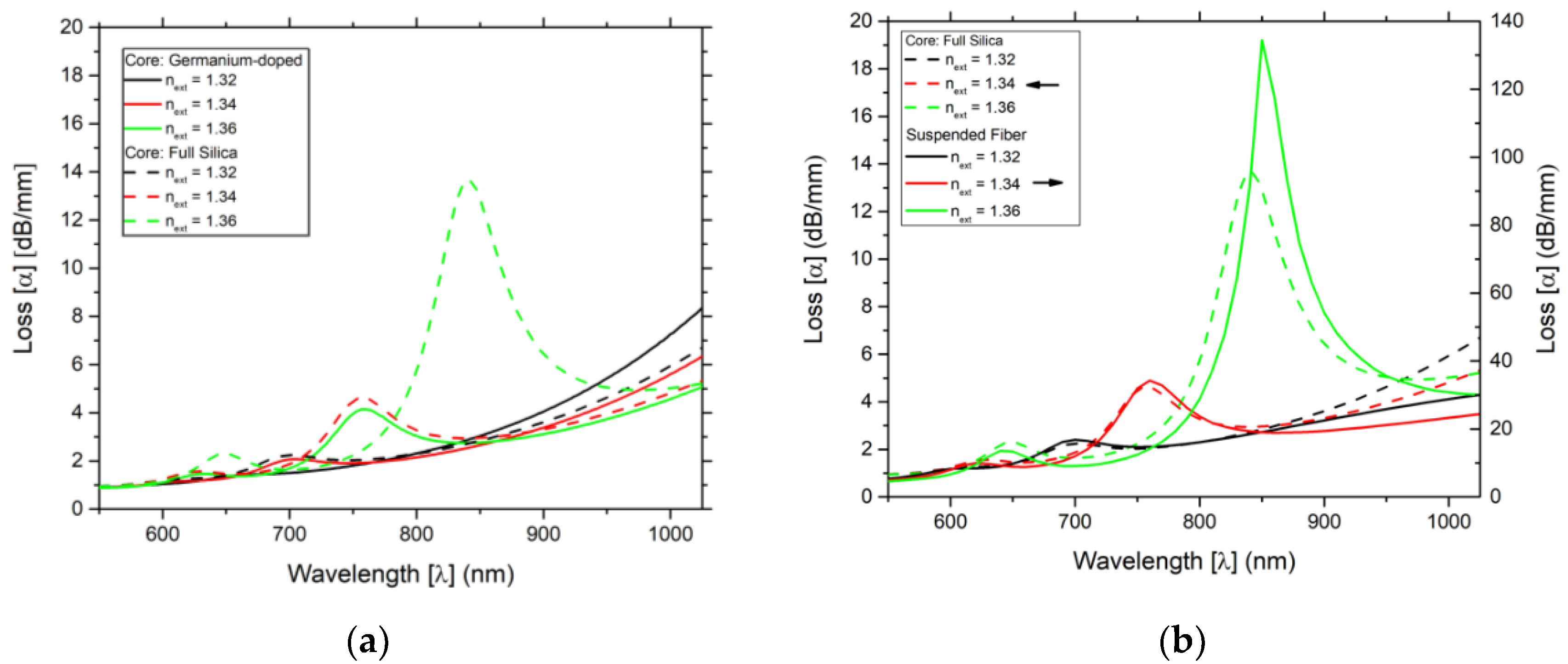
Figure 4 shows the loss as function of wavelength, for different values of the external refractive index of 1.32 to 1.36 for the two sensing structures based on D-type fiber (Figure 4a) and of the two best sensing structures, the D-type fiber with a core of pure silica and the suspend core fiber, sensing structure (Figure 4b). As referred from Figure 2 and Figure 3, it is clearly observable in Figure 4b that the losses are higher for the suspended core fiber, which gives an indication of potentially better sensitivities and resolutions. Again, this is attributed to the fact that the quantity of light in the suspended core fiber that interacts with the respective metallic wire is higher than in the other sensing structure based on the D-type fiber, resulting in higher resonance phenomena for the suspended core fiber configuration.
As indicated, in Figure 4b, the higher peak presents a better result when compared with the lower peak. For both sensing configurations (D-type fiber with a core of pure silica and the suspend core fiber) and for the three values of the external refractive index [1.32, 1.34, and 1.36] the variation of the wavelength of the higher peak is substantially larger than of the lower peak.
Qualitatively, the results indicate the importance of promoting the coupling of the fundamental core modes and the localized plasmon modes by increasing the overlap of their power distribution while guaranteeing the intersection of their dispersion curves. This is consistent not only with the results of previous simulations [4,5,6,20] and experimental works [21,22], but also the predictions of the mode coupling theory [19].
Table 1 shows the sensitivity and resolution of the external refractive index for the three optical fiber sensing configurations (germanium doped core D-type fiber, pure silica core D-type fiber, and suspend core fiber). Using the data of Figure 4 and the Equations (3) and (4), the resolution and the sensitivity were obtained considering an experimental spectral variation detection of 0.1 nm. As predicted, the suspend core fiber presented overall the best results for the ranges of the external refractive index tested, followed by the pure silica core D-type fiber. The poorer results in terms of sensitivity and resolution were for germanium doped core D-type fiber.

4. Conclusions

The characteristics of localized plasmonic modes of the metal nanowire and their coupling with the fundamental optical guided mode depend on the type of materials employed in the sensing structures, and also on the geometry of the distinct components and their relative position. These features impact the optical power spatial distributions of the different modes and ultimately their overlap and coupling. In this article, we used numerical simulations based on FEM method to validate the relevance of shaping the characteristics of the fundamental guided optical mode to promote the coupling with the localized plasmonic modes of the metal nanowire, in the two types of optical fibers studied. The results favored clearly the suspended core fiber since the less confinement of the light in the core, in conjunction with its slightly rounded configuration, promotes a stronger resonant coupling between the guided mode and the metallic nanowire plasmonic modes, resulting in an enhanced sensitivity and resolution. Finally, the suspended core fiber in conjunction with a metallic nanowire has a lot of potential to improve further its plasmonic sensing capacities, both in its sensing properties, as well as in the number of physical parameters that can be detected.

Author Contributions

The work described in this article is the collaborative development of all authors. Conceptualization, A.G., D.S. and J.M.B.; Methodology, A.G., D.S. and J.M.B.; Software, A.G. and D.S.; Investigation, A.G., D.S. and J.M.B.; Writing—Original Draft Preparation, D.S. and J.M.B.; Writing—Review A.G., & Editing, D.S. and J.M.B.; Supervision, A.G. and J.M.B.

Funding

This work is financed by the ERDF—European Regional Development Fund through the Operational Program for Competitiveness and Internationalization—COMPETE 2020 Program and by National Funds through the Portuguese funding agency, FCT—Fundação para a Ciência e a Tecnologia within project “GreenNanoSensing” POCI-01-0145-FEDER-032257. Diego Santos would like to thank the support of the Post-Doc scholarship, in the framework of Project Pest-OE/UID/FIS/50010/2013.

Conflicts of Interest

The authors declare no conflict of interest.

References

  1. Moayyed, H.; Leite, I.T.; Coelho, L.; Santos, J.L.; Viegas, D. Analysis of Phase Interrogated SPR Fiber Optic Sensors with Bimetallic Layers. IEEE Sens. J. 2014, 14, 3662–3668. [Google Scholar] [CrossRef]
  2. Jorge, P.A.S.; Silva, S.O.; Gouveia, C.; Tafulo, P.; Coelho, L.; Caldas, P.; Viegas, D.; Rego, G.; Baptista, J.M.; Santos, J.L.; et al. Fiber Optic-Based Refractive Index Sensing at INESC Porto. Sensors 2012, 12, 8371–8389. [Google Scholar] [CrossRef] [PubMed] [Green Version]
  3. Rodrigues Ribeiro, R.S.; Dahal, P.; Guerreiro, A.; Jorge, P.A.S.; Viegas, J. Fabrication of Fresnel plates on optical fibres by FIB milling for optical trapping, manipulation and detection of single cells. Sci. Rep. 2017, 7, 4485. [Google Scholar] [CrossRef] [PubMed]
  4. Santos, D.F.; Guerreiro, A.; Baptista, J.M. SPR Microstructured D-Type Optical Fiber Sensor Configuration for Refractive Index Measurement. IEEE Sens. J. 2015, 15, 5472–5477. [Google Scholar] [CrossRef]
  5. Santos, D.F.; Guerreiro, A.; Baptista, J.M. Surface plasmon resonance sensor based on D-type fiber with a gold wire. Optik 2017, 139, 244–249. [Google Scholar] [CrossRef]
  6. Santos, D.F.; Guerreiro, A.; Baptista, J.M. Numerical investigation of a refractive index SPR D-type optical fiber sensor using COMSOL multiphysics. Photonic Sens. 2013, 3, 61–66. [Google Scholar] [CrossRef]
  7. Lee, B.; Roh, S.; Park, J. Current status of micro- and nano-structured optical fiber sensors. Opt. Fiber Technol. 2009, 15, 209–221. [Google Scholar] [CrossRef]
  8. Bhandari, S.; Agrawal, V.V.; Birader, A.M. Fiber optics based surface plasmon resonance for label-free optical sensing. Indian J. Pure Appl. Phys. 2017, 55, 349–362. [Google Scholar]
  9. Gupta, B.; Shrivastav, A.; Usha, S. Surface Plasmon Resonance-Based Fiber Optic Sensors Utilizing Molecular Imprinting. Sensors 2016, 16, 1381. [Google Scholar] [CrossRef]
  10. Klantsataya, E.; Jia, P.; Ebendorff-Heidepriem, H.; Monro, T.; François, A. Plasmonic Fiber Optic Refractometric Sensors: From Conventional Architectures to Recent Design Trends. Sensors 2016, 17, 12. [Google Scholar] [CrossRef]
  11. Rifat, A.A.; Ahmed, R.; Yetisen, A.K.; Butt, H.; Sabouri, A.; Mahdiraji, G.A.; Hyun, S.; Adikan, F.R.M. Sensors and Actuators B: Chemical Photonic crystal fiber based plasmonic sensors. Sens. Actuators B Chem. 2017, 243, 311–325. [Google Scholar] [CrossRef]
  12. Tyagi, H.K.; Lee, H.W.; Uebel, P.; Schmidt, M.A.; Joly, N.; Scharrer, M.; Russell, P.S.J. Plasmon resonances on gold nanowires directly drawn in a step-index fiber. Opt. Lett. 2010, 35, 2573–2575. [Google Scholar] [CrossRef] [PubMed]
  13. Doherty, B.; Csáki, A.; Thiele, M.; Zeisberger, M.; Schwuchow, A.; Kobelke, J.; Fritzsche, W.; Schmidt, M.A. Nanoparticle functionalised small-core suspended-core fibre—A novel platform for efficient sensing. Biomed. Opt. Express 2017, 8, 790. [Google Scholar] [CrossRef] [PubMed]
  14. Wang, N.; Zeisberger, M.; Huebner, U.; Giannini, V.; Schmidt, M.A. Symmetry-breaking induced magnetic Fano resonances in densely packed arrays of symmetric nanotrimers. Sci. Rep. 2019, 9, 2873. [Google Scholar] [CrossRef] [PubMed] [Green Version]
  15. Wang, N.; Zeisberger, M.; Hübner, U.; Schmidt, M.A. Boosting Light Collection Efficiency of Optical Fibers Using Metallic Nanostructures. ACS Photonics 2019, 6, 691–698. [Google Scholar] [CrossRef]
  16. Cox, F.M.; Lwin, R.; Large, M.C.J.; Cordeiro, C.M.B. Opening up optical fibres. Opt. Express 2007, 15, 11843. [Google Scholar] [CrossRef]
  17. Kretschmann, E.; Raether, H. Radiative Decay of Non Radiative Surface Plasmons Excited by Light. Z. Nat. A 1968, 23, 2135–2136. [Google Scholar] [CrossRef]
  18. Schmidt, M.A.; Russell, P.S. Long-range spiralling surface plasmon modes on metallic nanowires. Opt. Express 2008, 16, 13617. [Google Scholar] [CrossRef]
  19. Guerreiro, A.; Santos, D.F.; Baptista, J.M. New Trends in the Simulation of Nanosplasmonic Optical D-Type Fiber Sensors. Sensors 2019, 19, 1772. [Google Scholar] [CrossRef]
  20. Santos, D.F.; Guerreiro, A.; Baptista, J.M. Simultaneous Plasmonic Measurement of Refractive Index and Temperature Based on a D-Type Fiber Sensor with Gold Wires. IEEE Sens. J. 2017, 17, 2439–2446. [Google Scholar] [CrossRef]
  21. Leite, I.T.; Hierro-Rodríguez, A.; Silva, A.O.; Teixeira, J.M.; Sousa, C.T.; Fernández-García, M.P.; Araújo, J.P.; Jorge, P.A.S.; Guerreiro, A. Exciting the optical response of nanowire metamaterial films on the tip of optical fibres. Phys. Status Solidi 2013, 7, 664–667. [Google Scholar] [CrossRef]
  22. Cennamo, N.; Coelho, L.; Santos, D.F.; Baptista, J.M.; Guerreiro, A.; Jorge, P.A.S.; Zeni, L. Modal Filtering for Optimized Surface Plasmon Resonance Sensing in Multimode Plastic Optical Fibers. IEEE Sens. J. 2015, 15, 6306–6312. [Google Scholar] [CrossRef]
Figure 1. Structure designs of the two D-type fibers (a) and of the suspend core fiber (b), all of them with a gold wire placed in the upper space that is filled with external refractive index. To allow a better visualization of the refractive indexes involved in the three fiber configurations, a bar in the right side of the figure makes the correspondence of the greyscale to the refractive index.
Photonics 06 00100 g001
Figure 2. (a) RI real and imaginary part of the two D-type fiber sensors as function of wavelength for an external refractive index of 1.36. The blue solid line corresponds to the D-type pure silica core fiber, and the red solid line corresponds to the D-type with a core silica doped with 16% germanium fiber. The crossing between the dispersion curves of the metal nanowires’ modes and the fundamental modes of the fibers are indicated by the circular dots and match the frequencies of the peaks (supermodes A–D), indicated by the squared dots. (b) Detailed distribution of the light intensity in the cores and in the wires for the referred supermodes.
Photonics 06 00100 g002
Figure 3. (a) RI real and imaginary part of the suspended core fiber sensing structure as function of wavelength for an external refractive index of 1.36. The crossing between the dispersion curves of the metal nanowire modes and the fundamental mode of the fiber are indicated by the circular dots and match the frequencies of the peaks (supermodes E and F), indicated by the squared dots. (b) Detailed distribution of the light intensity in the core and in the wire for the referred supermodes.
Photonics 06 00100 g003
Figure 4. Loss as function of wavelength for different values of the external refractive index of 1.32 to 1.36. (a) Results for the D-type fiber sensing structures with a core of pure silica. (b) Results for the D-type fiber with a core of pure silica and for the suspend core fiber structures. Notice that the losses for the losses for the pure silica fiber are measured on the scale on the left, while the suspended core fiber are measured on the scale on the right.
Photonics 06 00100 g004
Table 1. Sensitivity, resolution for the three refractive index optical fiber sensing configurations.
Range of nextSensitivity (nm)Resolution (10−5 RIU)
Germanium Doped CorePure Silica CoreSuspend Core FiberGermanium Doped CorePure Silica Core Suspend Core Fiber
[1.31, 1.32]1820208020905.4954.8084.785
[1.32, 1.33]1810257026605.5253.8913.759
[1.33, 1.34]1960321031105.1023.1153.215
[1.34, 1.35]2410388043704.1492.5772.288
[1.35, 1.36]2910425046403.4362.3532.155
[1.36, 1.37]4090643089702.4451.5551.115

