1. Introduction
Collective light emission effects arising from ensembles of quantum emitters are of great relevance from both fundamental and technological points of view. From a theoretical standpoint, collective effects give rise to new phenomena that enhance our understanding of basic light–matter interaction processes. Some examples include superradiance [
1,
2], subradiance [
3,
4], collective Lamb shift [
5,
6], modification of temporal correlations [
7,
8], strengthening of the coupling to an optical mode [
9], and the interplay between strong coupling and quenching [
10]. From a more practical perspective, the emission properties of ensembles of quantum emitters are relevant for the design of nonclassical light sources, which are of general interest for quantum technologies [
11,
12,
13].
Recently, there has been increasing attention to the fabrication of arrays of quantum emitters with control over the positions of their individual elements. In particular, very impressive advances have taken place in the field of optical manipulation of cold atoms. Nowadays, it is possible to deterministically build one-dimensional (1D) [
14], two-dimensional (2D) [
15], and even three-dimensional (3D) [
16,
17] arrays with quite arbitrary geometries and control of each individual position of several tens of elements. Fixing the positions of solid-state quantum emitters is more challenging. Nevertheless, there have been promising demonstrations of 2D array geometries based on diamond nanopillars containing silicon vacancy centers [
18], the optical writing of quantum dots in hydrogenated quantum wells [
19], and atomically thin semiconductors (tungsten diselenide
) stationed on top of patterned surfaces [
20] and even coupled with on-site plasmonic cavities [
21]. It is likely that future advances will provide even finer control over the position and emission properties of arrays of quantum emitters.
Explorations of emission phenomena induced by the geometry of an array of quantum emitters is facilitated by these fabrication advances. Motivated by the associated potential for discovering exotic physic phenomena and realizing practical engineering applications, we recently introduced the concept of quantum antenna arrays [
22]. Instead of the standard focus on the interactions between the individual emitters, we took inspiration from classical antenna arrays and placed an emphasis on the interference phenomena arising from superpositions of the fields radiated by ensembles of quantum emitters. Particular interest was guided by the known fact that (classical) antenna arrays employ interference to enhance the directive properties of their individual elements by radiating their composite fields into one or more desired directions [
23,
24,
25,
26]. In an analogous but essentially different manner, the geometry of quantum antenna arrays can be designed to provide control over the directional properties of the correlations between their measured photons. The original analysis in [
22] was restricted to first- and second-order directional correlation functions. Here, we extend that work and evaluate the
-order directional correlation for an array of
N initially excited quantum emitters. Previous works have studied the
-order directional correlation function [
27]. However, our analysis focuses on the appearance of grating lobes, and how their role impacts the characteristics of higher-order photon correlations. We note that other recent works have also pursued antenna array concepts for analyzing the emission from arrays of quantum emitters, either to shape the emission of a single photon [
28,
29] or to control two-photon correlations by either designing the initial state [
30] or continuously driving one element and controlling the interactions [
31].
The remainder of the manuscript is organized as follows. First, we introduce the theoretical framework in
Section 2. We then use it in
Section 3 to derive a tractable expression for the evaluation of the
-order directional correlation function. Next, we make use of this expression in
Section 4 to reveal different aspects of directional photon bunching with particular attention on the role of the grating lobes in the corresponding patterns. Examples are given to illustrate the main results. Finally, conclusions and future perspectives are presented in
Section 5.
2. Theoretical Framework
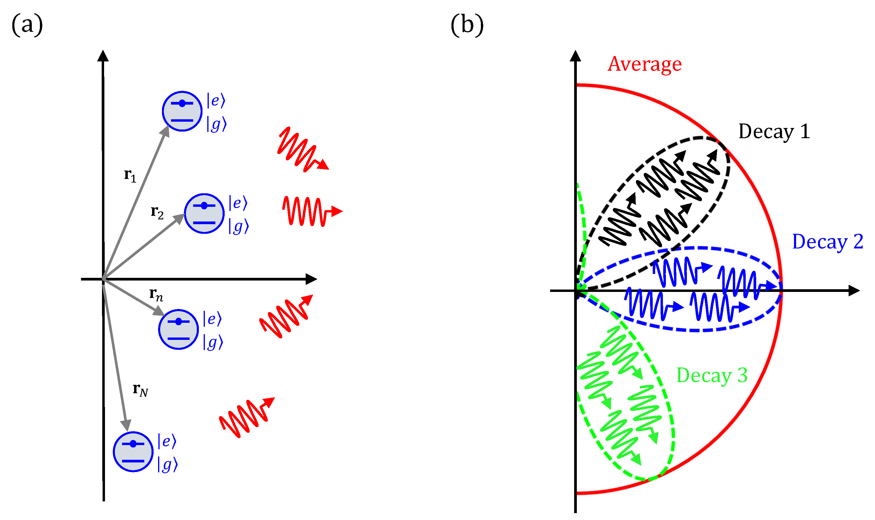
We start by considering a generic array of
N emitters located at positions
(see
Figure 1a). We assume that all emitters are identical and can be modelled as two-level systems,
, with an angular transition frequency
and dipole moment
. We also assume that all of the emitters are initially excited, i.e., the initial state of the quantum emitter’s subsystem can be written as follows:
More complex initial states could be considered to further understand how one might control photon correlations. However, this initial configuration is of particular interest from a practical standpoint. In particular, (
1) is a factored state that does not require the emitters to interact during their preparation process nor preserve the long-range entanglement between them. Furthermore, the initial state (
1) can be prepared by independently exciting each emitter with an initialization pulse. The main practical obstacles of this configuration are that all emitters must be identical and that the time uncertainty in the initialization of the emitters must be much smaller than the emitter’s lifetime.
The quantum emitters will decay from this initial state via spontaneous emission. By analyzing the fields generated during this process, we gain access to different photon correlations that predict the outcomes of relevant measurements. For example, the probability density per
per
of measuring
L photons along the
directions at times
is proportional to the following field correlation [
32,
33]:
where
(
) is the relevant positive (negative) frequency electric field operator [
32,
33]. In many experiments, one is interested in the directional properties of the emissions, irrespective of the times at which detection of the photons occurs. In order to gain insight into their directional correlations, we define the time-integrated field correlation:
Specifically, the
time-integrated correlation functions are proportional to the average number of L-photon coincidence measurements for any time delay [
22,
34]. Thus, they provide important information on whether or not the measurements of the emitted photons in different directions are correlated.
Finally, we note that if the emitters are weakly coupled, their interactions during their decay process can be neglected. The
correlation functions can then be written as the product of
functions, which takes into account the directionality of the individual dipole emitters and a generalized quantum array factor that represents the overall interference pattern, and it also takes into account the impact of the geometry of the array [
22].
where we have introduced the generalized quantum array factor [
22]:
3. Evaluation of the -Order Directional Correlation Function
Equations (
4) and (
5) provide a relatively simple theoretical framework for studying correlations between the directions in which the photons are measured. In addition, the introduction of the generalized array factor provides an immediate connection with the classical antenna theory [
23,
24,
25,
26]. This feature makes it possible to point out the most essential differences between classical and quantum antenna arrays, as well as to establish fundamental analogies. However, it becomes an increasingly complex task to examine the generalized array factor, as given by Equation (
5) when the order
L of the correlation increases. For this reason, previous analyses have been restricted to studying the 1st- and 2nd-order correlation functions [
22]. Here, we explicitly evaluate the
-order correlation function. Since our model assumes that the number of excitations is preserved, this is the highest-order nontrivial correlation function, i.e.,
for
. We will demonstrate that it is possible to derive a tractable expression for this extreme case.
To this end, let
with
be a basis for all possible states of the array of
N emitters. This basis can be arbitrary. Nevertheless, we define only for convenience the first state of this basis as all emitters being in their ground state, i.e.:
. One then finds the identity:
We then introduce the identity operator
between the composite operator
in Equation (
5) for
. This step allows us to rewrite the generalized quantum array factor as:
where we have defined
for
and
in the rest of the cases. This definition of
implies that the sum in Equation (
7) runs over all possible permutations of the
position vectors in the associated product of exponentials:
Therefore,
is given by the magnitude squared of a sum over the
permutations of the indices of Equation (
8). For example, we would then have for
emitters:
and for
emitters:
Intuitively, these results can be understood in terms of the "which-path" information that becomes available for any given state of the quantum emitter subsystem. After measuring a
N-photon coincidence event, the emitter’s subsystem must necessarily be in the ground state, i.e.,
. Therefore, the state of the emitters contains no information as to which emitter radiated the photon measured at a given detector. This means there is no which-path information and, as a consequence, quantum interference can occur. In this manner, each of the permutations in (
5) can be understood as a different path that connects the detection of a photon in each
direction to the emitter at the
location.
This analysis indicates that the
-order correlation function for an array of
N initially excited emitters maximizes the quantum interference with respect to any lower-order correlation functions. Indeed, the other extreme effect corresponds to the first-order correlation function, studied in [
22]. The first-order array factor is given by:
with the initial state correlation functions:
given by Equation (
1). This outcome leads to an absence of interference, i.e., the geometry of the array induces no directionality in the average number of photons measured as a function of direction giving
. Again, this effect can be intuitively understood in terms of the "which-path" information. The action of a single
operator projects the initial state
onto
. Thus, it is then possible to identify the emitter from which the photon originated. We further note that similar considerations of vanishing interference can be applied to the design of an isotropic single-photon source with emitters which have degenerate ground states [
35].
Therefore, the directional correlations for an array of initially-excited emitters are characterized by the absence of interference in the 1st-order correlation function, i.e., in the average number of photons measured in a given direction, while there are directional effects in higher-order correlation functions [
22,
27]. In fact, the
-order correlation function represents the maximal interference effects, which will lead to the directive phenomena. Physically, this feature implies that the photons are emitted as a superposition of photon bunches (see
Figure 1b). Therefore, the measurement of a single array decay process will show that the emitted photons appear bunched along preferred directions (constructive interference), while avoiding other forbidden directions (destructive interference). At the same time, if one averages the measurements over many array decay processes, it will be found that there is an isotropic distribution of the number of photons measured per direction, following the first-order correlation function.
4. Directional Photon Bunching
Equation (
7) provides a convenient theoretical framework for studying
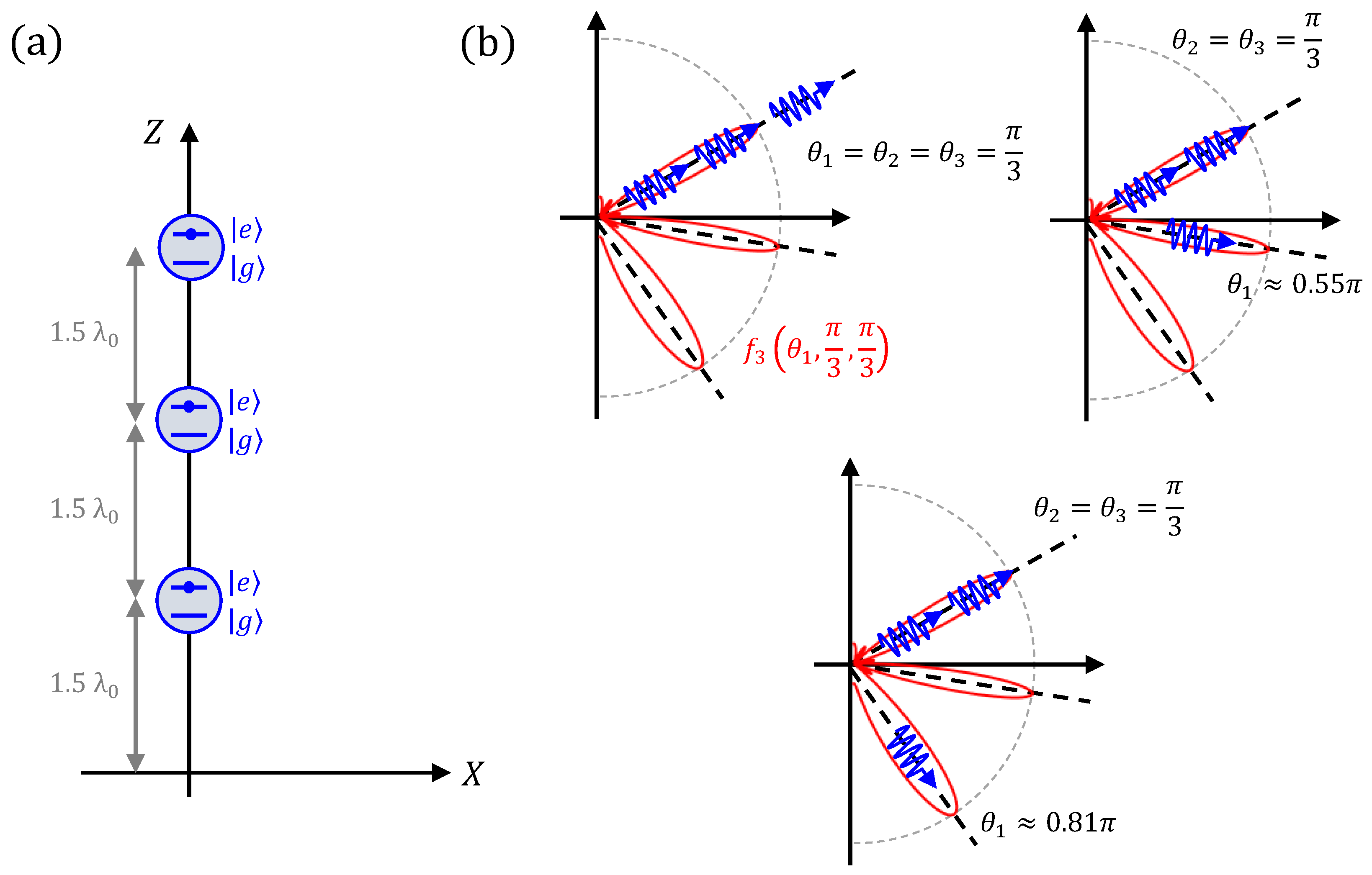
-order correlation effects and the characteristics of the expected photon bunches. We start by analyzing a limiting case before introducing more general photon correlation examples. It allows for a simple formulation, while at the same time providing some important insights into the characteristics of directional photon bunching in the emissions from ensembles of quantum emitters. Specifically, we consider a vertical linear array with emitters positioned along the Z-axis, i.e,
for
. Due to the rotational symmetry of this configuration about the Z-axis, only variations in the
elevation angles in the direction of the unit vector
will impact the array factor. In addition, we assume that
of the
N evaluation directions are identical, i.e.,
and
. Consequently, only the changes in the position of the
index will affect the product of exponentials given by Equation (
8). Under these conditions, the sum in Equation (
7) is composed of
N different addends repeated
times. Thus, the generalized quantum array factor reduces to:
with
. Note that the phase factor that is independent of
n can be taken outside the sum. This manipulation yields:
This interesting expression tells us that the array factor is proportional to the magnitude squared of the classical array factor of a linear array of classical time-harmonic emitters that are uniformly excited at the angular frequency
[
23,
24,
25,
26]. Therefore, although directional photon bunching is a quantum effect, this simple expression allows us to translate, by mathematical analogy, some results from the basic classical antenna array theory to the study of higher-order correlations in arrays of quantum emitters.
First, the classical array factor is maximized for . This can be understood quantum- mechanically as directional photon bunching. In particular, if we know that photons have been measured at the angle , the most likely direction in which the remaining photon will be measured must also be . This means that all of the photons tend to be bunched along the same direction.
Second, the directivity of a classical linear array increases along with the number of elements for a fixed separation distance. The analogous effect in terms of the photon correlation functions is that an increase in the size of the array and the number of photons measured along a given direction narrows down the range of angles along which the remaining photons are likely to be measured. We re-emphasize that these directive effects occur in the higher-order correlation functions even though there are none in the first-order correlation function. In contrast with a classical antenna array, an increase in the size of an array of initially-excited quantum emitters does not increase the directivity of the average number of photons.
Finally, if the separation between the emitters is sufficiently large, the classical antenna array theory has established that grating lobes will appear in the radiation patterns. The appearance of grating lobes means that the radiation is no longer concentrated into a single, well-defined direction; rather, it is split into different ones. It is clear for photon correlations that the evaluation of
and
in Equation (
12) produces the same behaviors. However, this effect can only be observed if the separation between the emitters
d is large enough so that
lies within the so-called "visible region":
. Once this happens, the appearance of grating lobes dramatically affects the photon-bunching phenomena. Since there is no difference between the
and
directions, any distribution of the photons between those two directions will occur with the same probability. As schematically depicted in
Figure 2, it is equally likely to measure one photon in
and
photons in
, two photons in
and
photons in
, ...,
photons in
and one photon in
. Therefore, once grating lobes appear, the photons do not necessarily tend to appear together (to be bunched) around the same direction. They are distributed along a discrete set of correlated directions, i.e., the grating lobe directions. This conclusion emphasizes that photon bunching is ultimately an interference effect and not the result of interactions between the photons.
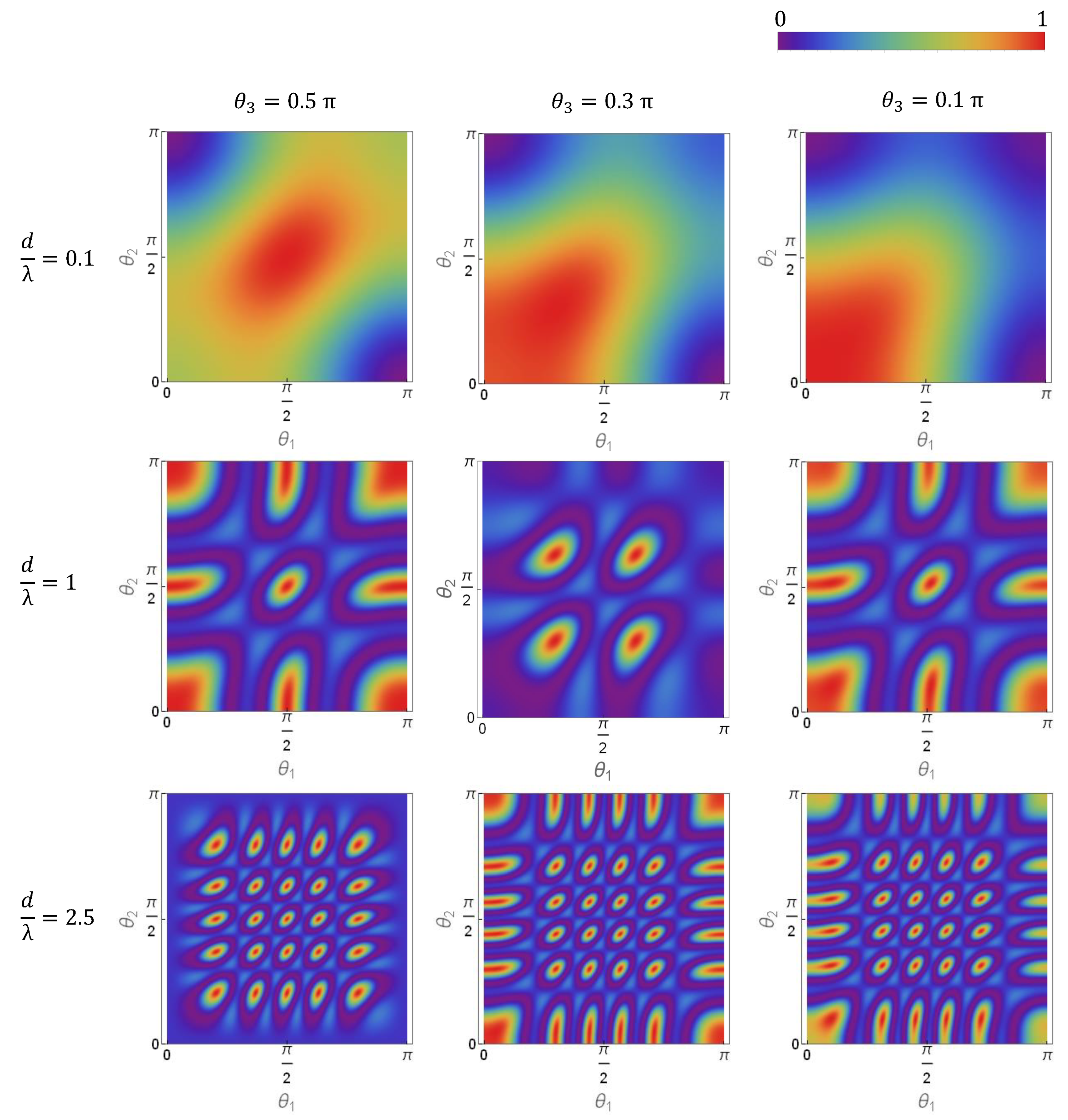
In order to shed more light on this effect,
Figure 3 includes an extensive parametric analysis of the generalized quantum array factor for a linear vertical array of
uniformly-spaced elements. It is graphically presented as a function of the element separation distance,
d, and the evaluation directions, (
). As anticipated, very different behaviors are observed as a function of the separation distance between the emitters. For a subwavelength separation,
(
being the wavelength at the transition frequency), the quantum array factor is always maximized at the points at which all three evaluation directions are identical, i.e.,
. This means the photons tend to be bunched around the same direction for this subwavelength array. The beamwidth around the maximal direction decreases as the separation between the emitters increases.
Grating lobes begin to appear for sufficiently large separation distances between the array elements,
. The array factor in these cases is not maximized only at the points at which all of the evaluation directions are equal; there are multiple local maxima. Moreover, it has the same magnitude in those directions. Consequently, modulo the factor associated with the directivity of the individual emitters (element factor), this array factor feature represents the fact that measurement outcomes will occur with the same probability in those directions. In these grating-lobe cases, quantum interference no longer leads to pure directional photon-bunching, but rather to the existence of correlated directions. Much like in the classical antenna theory, the number of observed grating lobes increases monotonically along with the separation between the emitters. In fact, we note that for a separation of
, one already observes 5 grating lobes when two evaluation directions are fixed (see third row in
Figure 3).
Ultimately, the existence of too many grating lobes would hinder an experimental demonstration of these effects. Ideally, the evaluation of N-photon coincidence measurements requires a large number of photon counters with good angular resolution or a minimum of N photon counters and the ability to scan them over the entire direction space. A practical experimental demonstration of directional photon-bunching will have to be implemented by dividing the direction space into a relatively small number of angular sectors. On the other hand, since more than one grating lobe could lie within the same angular sector when the separation distance between the emitters is large, the associated directional correlations would be averaged out. Therefore, our parametric analyses suggest that separation distances comparable to the wavelength would be optimal for an experimental demonstration of directional photon-bunching and of the appearance of grating lobes with currently available technologies.


