Article

Optical Multilevel Pulse Width Modulation for Analog Mobile Fronthaul

Politecnico di Milano, Dipartimento di Elettronica, Informazione e Bioingegneria (DEIB), Piazza Leonardo da Vinci 32, 20133 Milano, Italy
*
Author to whom correspondence should be addressed.
Photonics 2018, 5(4), 49; https://doi.org/10.3390/photonics5040049
Submission received: 30 October 2018 / Revised: 16 November 2018 / Accepted: 20 November 2018 / Published: 23 November 2018
(This article belongs to the Special Issue Lightwave Communications and Optical Networks)

Abstract

:
The evolution of radio access networks is towards a centralized architecture (C-RAN), with massive antenna deployments and large radio-frequency bandwidths. In the next future, traditional optical transport technologies based on digital radio over fiber will no longer be able to support the mobile fronthaul traffic connecting antennas hosted at remote radio units and centralized baseband units. Analog radio over fiber can be selected to support the mobile fronthaul (MFH) network and, in particular, pulse width modulation (PWM) is a viable alternative for analog signal transport. In order to increase the MFH spectral efficiency, we propose to exploit multilevel PWM (M-PWM) in a wavelength division multiplexing-passive optical network (WDM-PON) network, comparing its performance with a conventional 2-level PWM solution. Experimental results show successful transmission over 7.5-km standard single mode fiber (SSMF) of up to 16 aggregated LTE-like 20-MHz signals with 64-QAM on each subcarrier, while up to eight aggregated LTE-like 20-MHz signals with 256-QAM could be supported. M-PWM thus allows either using higher order modulation formats or aggregating a higher number of LTE channels.

1. Introduction

Next mobile generations (e.g., 5G) are characterized by the growing ubiquitous demand of capacity and the necessity to support low-latency, and this leads to significant challenges to the existing optical and wireless access networks. Nowadays, the centralized radio access network (C-RAN) is widely accepted to be the preferred architecture to face these challenges, mainly induced by the explosive growth of mobile data caused by the exploitation of new mobile technologies (e.g., millimeter wave small cells, carrier aggregation, etc.). C-RAN is mostly designed to support a large number of wireless users taking advantage of coordinated multipoint (CoMP) transmission, carrier aggregation and multi-antenna massive multiple-input multiple-output (MIMO) deployment, consolidating signal processing and management functions into the baseband processing units (BBUs) [1,2]. The mobile fronthaul (MFH) segment, linking centralized BBUs and remote radio units (RRUs), must thus handle a large number of high-capacity point-to-point connections with minimal delay.
Today’s MFH communication is based on the common public radio interface (CPRI) that transmits digitized baseband in-phase and quadrature (IQ) streams of the radio frequency (RF) signals via digital modulations. Digitized bit/symbol streams are transported by the existing optical intensity modulation-direct detection (IM-DD) links. Digitization expands the RF bandwidth about 30 times (e.g., 20 MHz RF signal with 4-antenna MIMO needs 2.5 Gb/s for IQ digital streaming) and low-cost optical technologies for transmission will no longer be able to support it in the future [3,4,5]. To overcome this key issue, approaches based on CPRI data compression [6] or on the change of the functional split point have been proposed [7]. Nonetheless, these methods introduce some uncontrolled latency that prevent the use of cooperative methods for multiple RRUs as for CoMP [8]. Recently, a new digitization interface was demonstrated: it replaces the CPRI Nyquist analog to digital converter (ADC) with a delta–sigma modulator, obtaining a four-time increase in capacity without significant sacrifice of error vector magnitude (EVM) performance [9]. However, due to the necessary oversampling, very high-speed delta–sigma modulators are required, while only a few works in literature have demonstrated GS/s devices.
Alternatively, optical transmission technologies different from digital radio over fiber (D-RoF) can be adopted. In particular, analog MFH based on analog radio-over-fiber (A-RoF) features high spectral efficiency and transparency with respect to radio access technology (RAT) and waveforms. The direct relay of RF data over the fiber can be performed by multiple frequency-domain multiplexed (FDM) signals assisted by analog and digital signal processing [10,11] or by directly-modulated multiple intermediate frequency-over-fiber (IFoF) signals [12]. Due to the continuous envelope and high peak-to-average power ratio (PAPR) of multicarrier waveforms, analog MFH is susceptible to noise, linear and nonlinear distortions (NLD) and transmission impairments. Thus, analog MFH technologies often need the exploitation of advanced modulation formats, which lead to higher costs in terms of transmitter and receiver complexity, signal-processing aided demodulation and NLD suppression methods that increase the experienced latency of mobile links [13,14].
Recently, we have proposed another C-RAN architecture taking advantage of the splitting of signal sampling and quantization between the RRU and the BBU. This can be obtained exploiting the optical pulse-width modulation (O-PWM), which is a nonlinear modulation that encodes the analog samples at the transmitter onto the duration of the on/off keyed transmitted optical signals [15]. Indeed, the RF signal is harmonically sampled and PW modulated before transmission in the MFH fiber link. PWM transport of sampled signals for MFH combines the best features of analog and digital transmission: there is no bandwidth expansion and the optical signal is on-off keyed. We have demonstrated, for a 100-MHz RF signal, that O-PWM can represent an alternative analog coding to overcome some limitations previously made evident for RoF [16].
Multilevel PWM (M-PWM) [17] can be exploited to increase the number of aggregated channels that can be transmitted by O-PWM and to expand the system capacity to support LTE higher-order modulations. In this paper, we present a fiber optic MFH architecture based on the M-PWM able to support the transmission of up to 16 aggregated LTE channels. Section 2 presents the M-PWM transmission scheme. The M-PWM MFH architecture and the experimental setup are described in Section 3. In Section 4, we compare the performance of standard and multilevel PWM transmission of 8 20-MHz LTE-like aggregated channels with 64-QAM modulation on each subcarrier. We also demonstrate the exploitation of M-PWM modulation and demodulation in the uplink (RRU to BBU) transmission of 16 RF signals over 7.5 km of standard single mode fiber (SSMF) in a wavelength division multiplexed passive optical network (WDM-PON) architecture. Final discussion and conclusions are drawn in Section 5.

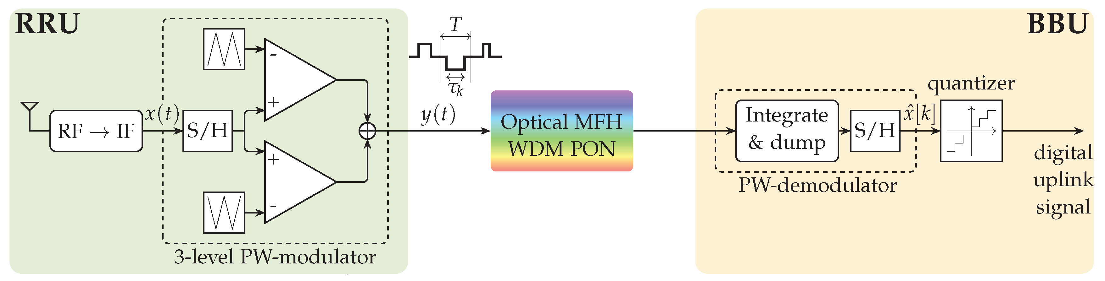
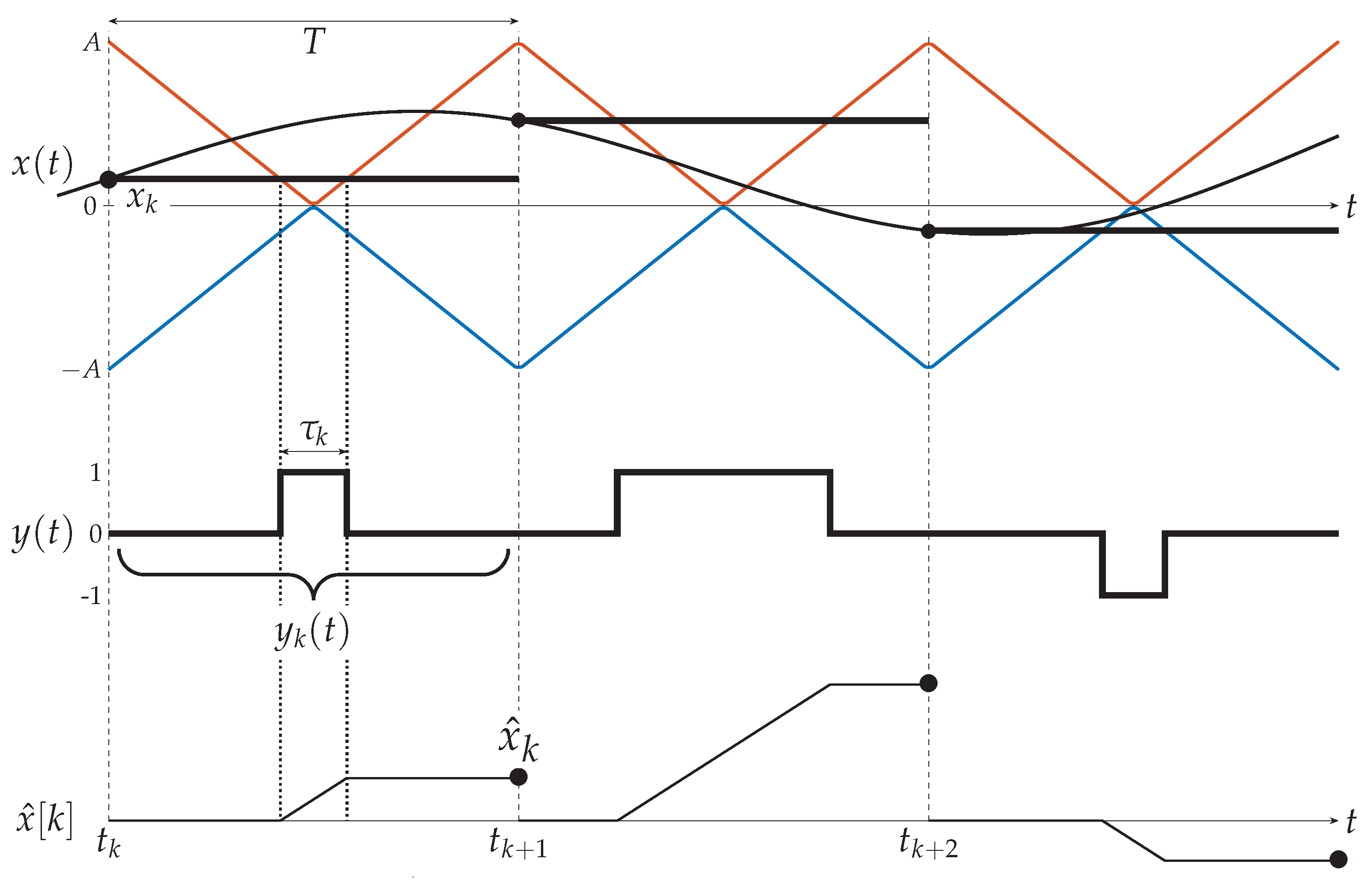
2. Multilevel PWM for Analog MFH

Multilevel PWM consists in encoding the sample amplitude of the input signal onto the duration and amplitude of a sequence of rectangular pulses, and it is a mixed width-amplitude modulation. In this work, 3-level PWM is proposed and experimentally validated for the analog MFH: the PWM pulses can assume two amplitude values (say ± 1 ), so that the PWM signal modulating the optical source presents an amplitude quantized into three levels { 1 , 0 , 1 } . In this way, the representation of a signal x ( t ) is obtained by means of both pulse duration τ and a binary variable (positive or negative amplitude), and the dynamic range for signal representation is effectively doubled. Figure 1 shows the proposed PWM architecture and the involved signals are depicted in Figure 2. Even though Figure 1 refers to the uplink transmission from RRU to BBU, the M-PWM system is envisioned for the downlink as well, with a minor adaptation of the following description. With reference to Figure 1, the received RF signal is down-converted to a suitable intermediate frequency (IF) and it is harmonically sampled. Differently from the conventional 2-levels PWM [15], the sampled signal x [ k ] , input to the PW-modulator, is compared to two different triangular waves, respectively red and blue in Figure 2. The two triangular waves, combined, cover the whole amplitude dynamic of the input signal: the red one in [ 0 , A ] and the blue one in [ A , 0 ] . The output signals of the two comparators are then summed to obtain the modulated 3-level PWM signal y ( t ) . The sampled signal is then encoded into pulses of duration τ k = | x k | / A and amplitude sign ( x k / A ) :
y ( t ) = k = y k ( t ) = k = sign ( x k / A ) · rect t t k T / 2 τ k ,
where T is the sampling interval. Demodulation is performed by an integrator that is periodically reset at the end of each sampling interval to obtain the estimated sampled signal x ^ [ k ] . In case of M-PWM with more than three amplitude levels, the integrator needs to be preceded by a decision on the received amplitude level. This is to avoid the amplitude-duration ambiguity that would arise from straightforward integration of the received signal.

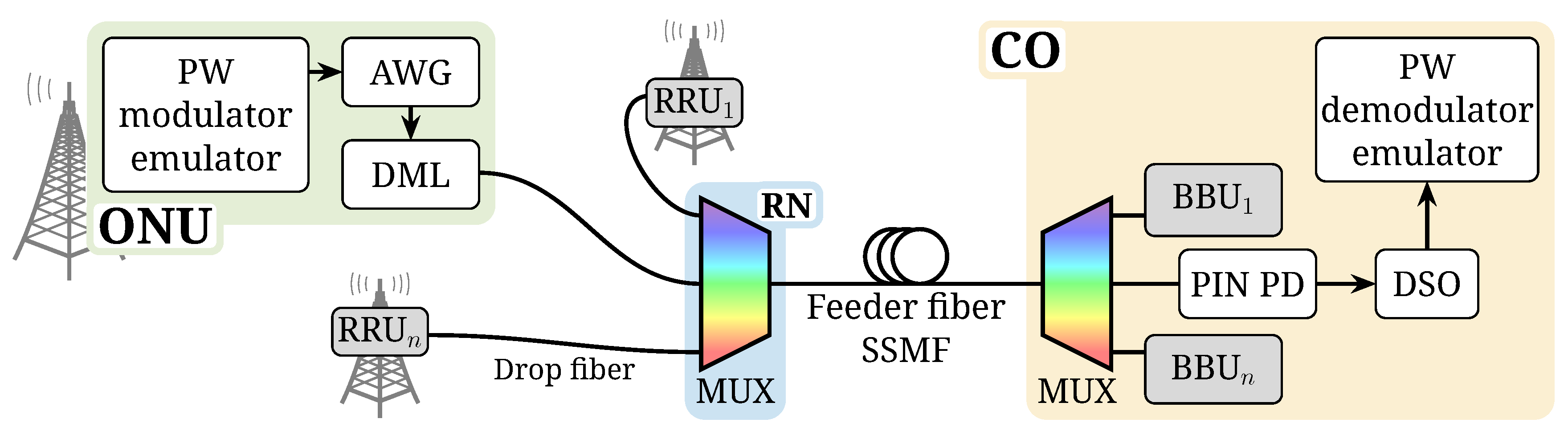
3. M-PWM MFH Architecture and Experimental Setup

The transmission scheme of Figure 1 is used to transport LTE-like signals aggregated via frequency division multiplexing (FDM) in a WDM-PON, as the one in Figure 3. The samples of the I and Q components are mapped onto the duration and (binary) amplitude of the transmitted rectangular pulses as previously described. In particular, the pulse duration is τ m i n < τ < τ m a x , where τ m i n depends on the electro-optic bandwidth of the fibre-optic network devices and τ m a x T . In this work, τ m a x = 0.9 T to avoid intersample interference that may arise due to pulse broadening. Moreover, to fairly compare conventional 2-level PWM and the 3-level PWM, the multilevel option is evaluated both taking advantage of the full duration dynamic, i.e., τ [ τ m i n , τ m a x ] , and with halved dynamic to compensate for the doubling deriving from the binary amplitude. The halved dynamic is τ [ τ ˜ m i n , τ ˜ m a x ] , where τ ˜ m i n > τ m i n and τ ˜ m a x < τ m a x , so that τ m a x τ m i n = 2 · ( τ ˜ m a x τ ˜ m i n ) . At the BBU, after detection, the demodulator transforms the M-PWM signal into amplitude samples by an integrator that is periodically reset every sampling interval T, as in conventional PWM. In this work, either 8 or 16 aggregated 20-MHz LTE-like signals are transmitted, so that the sampling interval is either T = 2 ns or T = 1 ns, respectively.
The experimental setup in Figure 3 describes the WDM-PON that supports the PWM MFH transmission. At the optical network unit (ONU), the M-PWM (uplink) signal drives a directly modulated laser (DML) with 15-GHz bandwidth. Such M-PWM signal is prepared via Matlab® and generated by a Tektronix® 50 GS/s arbitrary waveform generator (AWG) with 14-GHz bandwidth. After propagation through the drop fiber, signals coming from different ONUs are combined at the remote node (RN) via wavelength multiplexing and coupled to the SSMF feeder fiber. In particular, the MUX is a 32-channel athermal arrayed waveguide grating, which, if necessary, could be replaced by a power splitter in order to support TWDM-PON compliant optical distribution networks. At the central office (CO), the different RRUs signals are separated by the wavelength demultiplexer and sent to the corresponding receiver. Each receiver consists of a PIN photodiode (PD) with 12-GHz bandwidth that performs direct detection, followed by a pulse width demodulator. PW demodulation is performed via offline signal processing: the PD output signal is acquired by a Tektronix digital storage oscilloscope (DSO) with 8 bit vertical resolution, 50 GS/s sampling and 23-GHz electrical bandwidth. Offline processing via Matlab delivers pulse width demodulation consisting of signal thresholding and integration, together with the performance evaluation of the MFH link. Thresholding helps to reduce the noise level of the received signal, by comparing the received signal y r x ( t ) with a fixed value y ¯ t h and assigning to the received signal a value + 1 when y r x ( t ) > y ¯ t h , a value 1 when y r x ( t ) < y ¯ t h and a value 0 when y ¯ t h < y r x ( t ) < y ¯ t h .

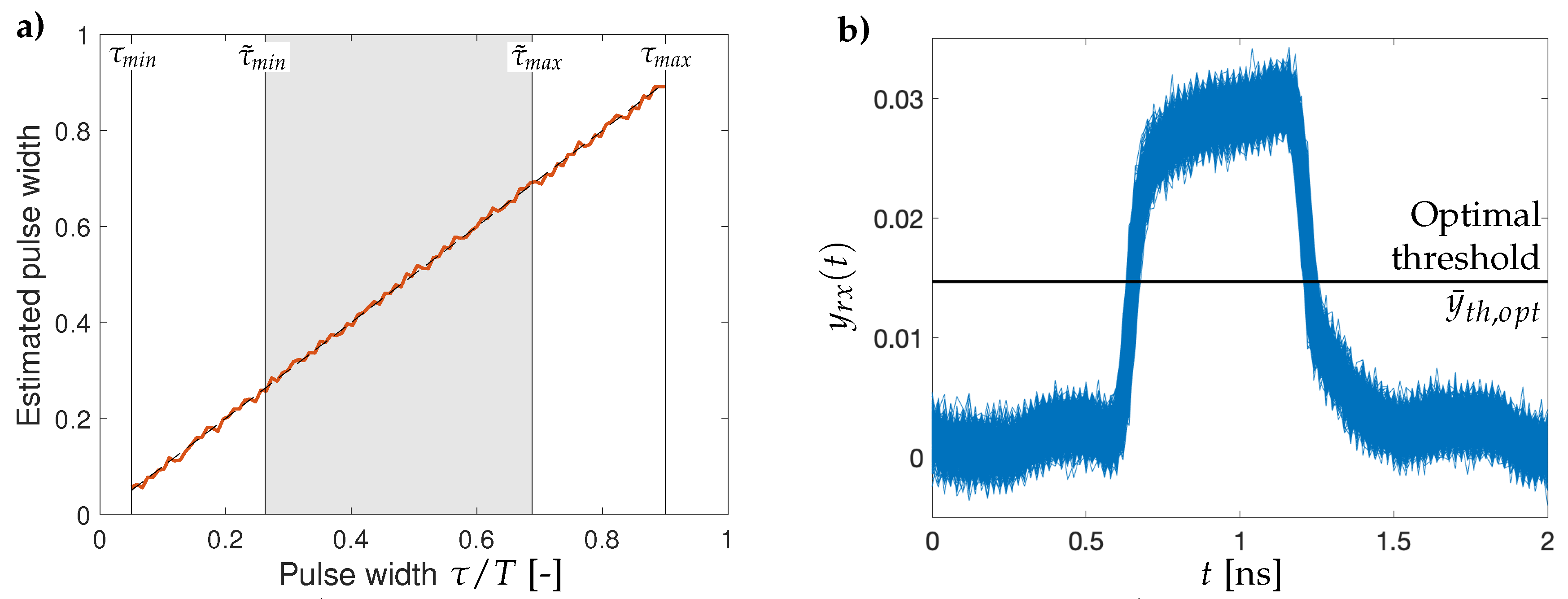
4. Experimental Results

System performance is assessed, after 7.5-km SSMF transmission, in terms of EVM to characterize the signal degradation introduced by the MFH segment.

4.1. Calibration Procedure

The performance assessment is preceded by a calibration procedure in which a sequence of pulses is transmitted, so that their duration values cover the whole pulse width dynamic. This allows for determining both the optimal threshold level y ¯ t h , o p t before integrating the received PWM signal and the amplitude-width correspondence of the entire link. An in-field unit would have to repeat the calibration procedure according to the aging dynamics of the optical and electronics devices. An example of the results of the calibration stage is presented in Figure 4: Figure 4a shows the calibration curve obtained for the cases of full and halved duration dynamics. All the received instances of the calibration pulse of duration τ = 0.27 T are displayed in Figure 4b, together with the optimal threshold level y ¯ t h , o p t . Such optimal threshold is chosen so as to minimize the average noise level of the received calibration signal.

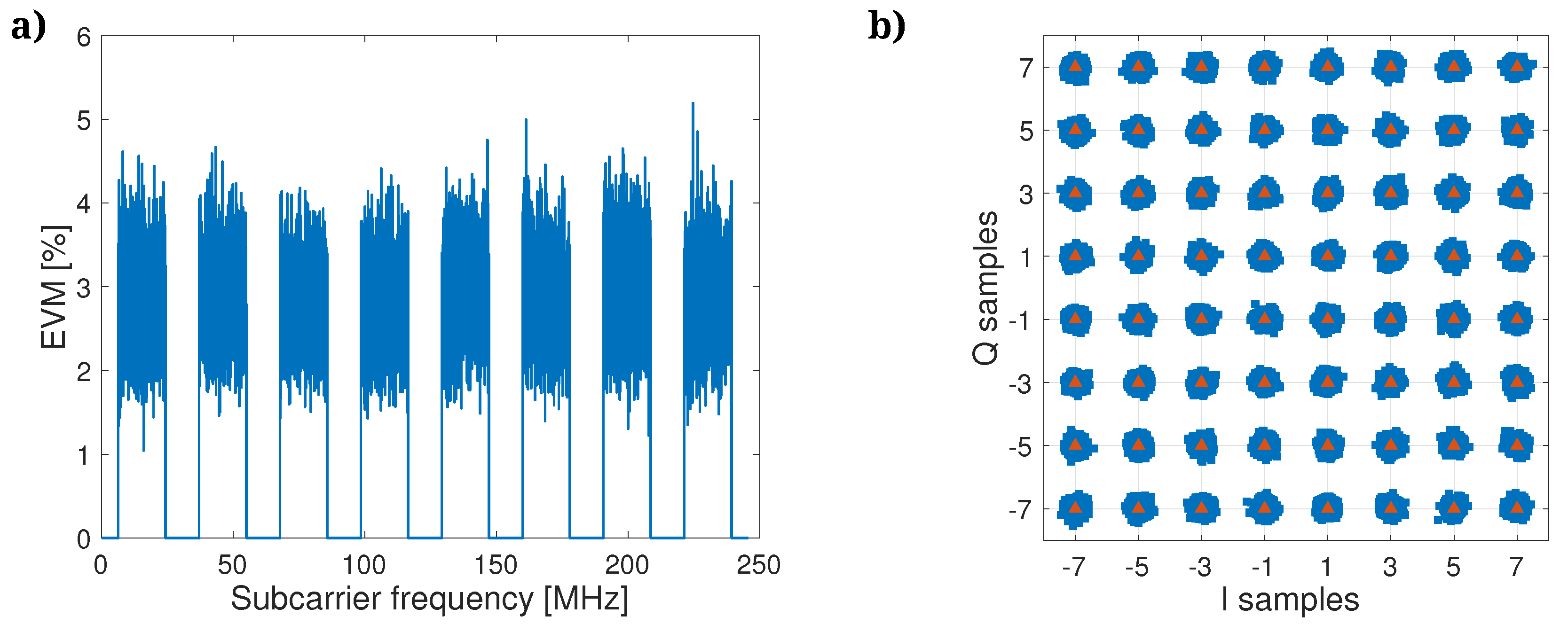
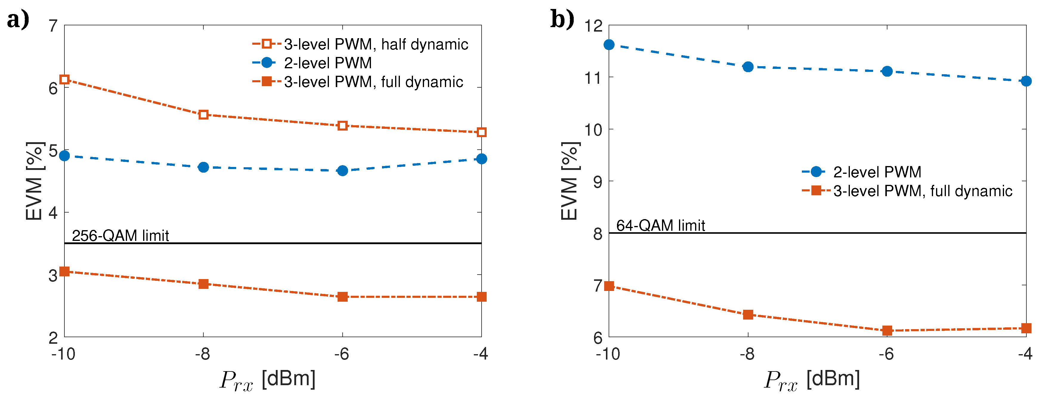
4.2. EVM Measurements

After the calibration step, the M-PWM architecture can be employed for the transmission of LTE-like mobile signals. Figure 5 presents the results for a received optical power P r x = 8 dBm, when a 3-level PWM signal with full duration dynamic is used for the MFH. In particular, Figure 5a shows the EVM per subcarrier for N c h = 8 aggregated LTE-like 20-MHz signals: each 20-MHz OFDM signal is composed of 1200 15-kHz subcarriers with 64-QAM modulation, plus 848 15-kHz guard subcarriers. Figure 5a shows similar EVM levels for all the 15-kHz subcarriers, thus, in the following results, the average EVM is considered as a performance metric. Figure 5b shows the received 64-QAM constellation per subcarrier.
The mean EVM after averaging along all the 1200 · N c h subcarriers is in Figure 6 for N c h = 8 (Figure 6a) and N c h = 16 (Figure 6b). Figure 6a compares the performance of the two codes with equal representation dynamics: as expected, the conventional 2-level PWM (full blue circles) performs slightly better than the half-dynamic 3-level PWM (open red squares). Anyways, both modulation formats guarantee an EVM level well below the 8% that is the LTE limit for 64-QAM. A full-dynamic 3-level PWM, on the other hand, results in an average EVM below the 256-QAM limit (3.5%), thus allowing the higher modulation format at least for some of the subcarriers. The difference in performance between 3-level and conventional PWM is even more apparent when considering 16 aggregated channel, as in Figure 6b. In this case, indeed, conventional 2-level PWM cannot satisfy the EVM specifications for 64-QAM, while 3-level PWM achieves an average EVM around 6%.

5. Conclusions

Multilevel pulse width modulation (M-PWM) is demonstrated to be a viable solution for MFH in C-RAN. The proposed M-PWM provides an alternative functional split of base station tasks between RRUs and BBUs, in which analog-digital conversion is split into sampling at the RRU and quantization at the BBU (referring to uplink) and M-PWM over optical fiber provides signal transport in between. M-PWM supports the expansion of system capacity either by enabling the aggregation of a higher number of RF signals or by allowing higher modulation formats. Moreover, avoiding the digitization at the RRU, there is no bandwidth expansion before the optical transmission, thus devices with lower bandwidths can be adopted for analog electronics, and any bandwidth distortion can be compensated to a certain extent. Experimental results show that M-PWM transmission, when transporting eight aggregated LTE-like signals, results in an average EVM < 3.5%, thus allowing for 256-QAM. M-PWM also empowers the aggregation of 16 20-MHz LTE-like signals guaranteeing EVM < 8% that is the limit for 64-QAM. Finally, as the system performance of the actual experimental set up is impaired by the high-speed digital-to-analog (at RRU) or analog-to-digital (at BBU) converters, an analog implementation of M-PWM is expected to overcome the time-granularity of current experiments.

Author Contributions

Conceptualization, U.S. and P.P.; Formal analysis, L.C.; Investigation, A.G.; Methodology, P.B.; Supervision, U.S.; Validation, A.G.; Writing—original draft, L.C.; Writing—review & editing, A.G. and P.P.

Funding

This research received no external funding.

Conflicts of Interest

The authors declare no conflict of interest.

References

  1. Checko, A.; Christiansen, H.L.; Yan, Y.; Scolari, L.; Kardaras, G.; Berger, M.S.; Dittmann, L. Cloud RAN for Mobile Networks—A Technology Overview. IEEE Commun. Surv. Tutor. 2015, 17, 405–426. [Google Scholar] [CrossRef] [Green Version]
  2. Pizzinat, A.; Chanclou, P.; Saliou, F.; Diallo, T. Things You Should Know About Fronthaul. J. Lightw. Technol. 2015, 33, 1077–1083. [Google Scholar] [CrossRef]
  3. Pfeiffer, T. Next generation mobile fronthaul and midhaul architectures. J. Opt. Commun. Netw. 2015, 7, B38–B45. [Google Scholar] [CrossRef]
  4. Udalcovs, A.; Levantesi, M.; Gaudino, R.; Urban, P.; Mello, D.A.A.; Ozolins, O.; Monti, P. An Insight into the Total Cost of Ownership of 5G Fronthauling. In Proceedings of the 2018 20th International Conference on Transparent Optical Networks (ICTON), Bucharest, Romania, 1–5 July 2018; pp. 1–5. [Google Scholar]
  5. Di Giglio, A.; Pagano, A. Scenarios and Economic Analysis of Fronthaul in 5G Optical Networks. J. Lightw. Technol. 2018. [Google Scholar] [CrossRef]
  6. Kim, S.H.; Chung, H.S.; Kim, S.M. Experimental demonstration of CPRI data compression based on partial bit sampling for mobile front-haul link in C-RAN. In Proceedings of the Optical Fiber Communication Conference, Anaheim, CA, USA, 20–22 March 2016. [Google Scholar]
  7. Miyamoto, K.; Kuwano, S.; Terada, J.; Otaka, A. Performance evaluation of mobile fronthaul optical bandwidth reduction and wireless transmission in Split-PHY Processing architecture. In Proceedings of the 2016 Optical Fiber Communications Conference and Exhibition (OFC), Anaheim, CA, USA, 20–24 March 2016; pp. 1–3. [Google Scholar]
  8. Gomes, N.J.; Assimakopoulos, P. Optical Fronthaul Options for Meeting 5G Requirements. In Proceedings of the 2018 20th International Conference on Transparent Optical Networks (ICTON), Bucharest, Romania, 1–5 July 2018. [Google Scholar]
  9. Wang, J.; Yu, Z.; Ying, K.; Zhang, J.; Lu, F.; Xu, M.; Cheng, L.; Ma, X.; Chang, G.K. Digital mobile fronthaul based on delta-sigma modulation for 32 LTE carrier aggregation and FBMC signals. IEEE/OSA J. Opt. Commun. Netw. 2017, 9, A233–A244. [Google Scholar] [CrossRef]
  10. Liu, X.; Zeng, H.; Chand, N.; Effenberger, F. Efficient mobile fronthaul via DSP-based channel aggregation. J. Lightw. Technol. 2016, 34, 1556–1564. [Google Scholar] [CrossRef]
  11. Zhu, M.; Liu, X.; Chand, N.; Effenberger, F.; Chang, G.K. High-capacity mobile fronthaul supporting LTE-advanced carrier aggregation and 8 × 8 MIMO. In Proceedings of the 2015 Optical Fiber Communication Conference, Los Angeles, CA, USA, 22–26 March 2015. [Google Scholar]
  12. Han, C.; Cho, S.H.; Chung, H.S.; Lee, J.H. Linearity improvement of directly-modulated multi-IF-over-fibre LTE-A mobile fronthaul link using shunt diode predistorter. In Proceedings of the 2015 European Conference on Optical Communication (ECOC), Valencia, Spain, 27 September–1 October 2015; pp. 1–3. [Google Scholar]
  13. Wang, J.; Liu, C.; Zhang, J.; Zhu, M.; Xu, M.; Lu, F.; Cheng, L.; Chang, G.K. Nonlinear inter-band subcarrier intermodulations of multi-RAT OFDM wireless services in 5G heterogeneous mobile fronthaul networks. J. Lightw. Technol. 2016, 34, 4089–4103. [Google Scholar] [CrossRef]
  14. Liu, X.; Zeng, H.; Chand, N.; Effenberger, F. Experimental demonstration of high-throughput low-latency mobile fronthaul supporting 48 20-MHz LTE signals with 59-Gb/s CPRI-equivalent rate and 2-μs processing latency. In Proceedings of the 2015 European Conference on Optical Communication (ECOC), Valencia, Spain, 27 September–1 October 2015; pp. 1–3. [Google Scholar]
  15. Combi, L.; Gatto, A.; Martinelli, M.; Parolari, P.; Spagnolini, U. Pulse-Width optical modulation for CRAN front-hauling. In Proceedings of the 2015 IEEE Globecom Workshops (GC Wkshps), San Diego, CA, USA, 6–10 December 2015; pp. 1–5. [Google Scholar]
  16. Parolari, P.; Gatto, A.; Combi, L.; Spagnolini, U.; Brenot, R.; Martinelli, M. Pulse width modulation for fronthaul in a broadband-seeded RSOA WDM PON. IEEE Photonics Technol. Lett. 2016, 28, 1625–1628. [Google Scholar] [CrossRef]
  17. Parolari, P.; Gatto, A.; Combi, L.; Boffi, P.; Martinelli, M.; Spagnolini, U. Multilevel pulse width modulation fibre optic transmission for next generation mobile fronthaul. In Proceedings of the 42nd European Conference on Optical Communication (ECOC 2016), Dusseldorf, Germany, 18–22 September 2016; pp. 1–3. [Google Scholar]
Figure 1. 3-level PWM mo-demodulation scheme with reference to the uplink.
Photonics 05 00049 g001
Figure 2. Examples of 3-level PWM signals. From top to bottom: input signal x ( t ) together with the two triangular reference waveforms, the M-PWM signal y ( t ) , and the estimated sample amplitude x ^ k after PW demodulation.
Photonics 05 00049 g002
Figure 3. WDM-PON PWM fronthauling and experimental setup.
Photonics 05 00049 g003
Figure 4. (a) calibration curve with highlighted duration domains: full ( τ m i n , τ m a x ) and halved ( τ ˜ m i n , τ ˜ m a x ) dynamics; (b) superimposition of the received instances obtained during the calibration stage for the pulse of duration τ = 0.27 · T .
Photonics 05 00049 g004
Figure 5. Percentage EVM against subcarrier frequency (a), and received constellation (b) for 3-level PWM with full dynamic, 8 aggregated 20-MHz LTE-like channels, 64-QAM, P r x = 8 dBm.
Photonics 05 00049 g005
Figure 6. Average percentage EVM against received optical power P r x , N c h = 8 (a) and N c h = 16 (b) aggregated 20-MHz LTE-like channels, 64-QAM.
Photonics 05 00049 g006

