Review

New Generation Wearable Antenna Based on Multimaterial Fiber for Wireless Communication and Real-Time Breath Detection

1
Center for Optics, Photonics and Lasers (COPL), Department of Physics, Université Laval, Québec, QC G1V 0A6, Canada
2
LABioTRON Bioengineering Research Laboratory, Department of Electrical and Computer Engineering, Research Centre for Advanced Materials (CERMA), Université Laval, Québec, QC G1V 0A6, Canada
*
Author to whom correspondence should be addressed.
Photonics 2018, 5(4), 33; https://doi.org/10.3390/photonics5040033
Submission received: 31 August 2018 / Revised: 20 September 2018 / Accepted: 30 September 2018 / Published: 11 October 2018

Abstract

:
Smart textiles and wearable antennas along with broadband mobile technologies have empowered the wearable sensors for significant impact on the future of digital health care. Despite the recent development in this field, challenges related to lack of accuracy, reliability, user’s comfort, rigid form and challenges in data analysis and interpretation have limited their wide-scale application. Therefore, the necessity of developing a new reliable and user friendly approach to face these problems is more than urgent. In this paper, a new generation of wearable antenna is presented, and its potential use as a contactless and non-invasive sensor for human breath detection is demonstrated. The antenna is made from multimaterial fiber designed for short-range wireless network applications at 2.4 GHz frequency. The used composite metal-glass-polymer fibers permits their integration into a textile without compromising comfort or restricting movement of the user due to their high flexibility, and shield efficiently the antenna from the environmental perturbation. The multimaterial fiber approach provided a good radio-frequency emissive properties, while preserving the mechanical and cosmetic properties of the garments. With a smart textile featuring a spiral shape fiber antenna placed on a human chest, a significant shift of the operating frequency of the antenna was observed during the breathing process. The frequency shift is caused by the deformation of the antenna geometry due to the chest expansion, and to the modification of the dielectric properties of the chest during the breath. We demonstrate experimentally that the standard wireless networks, which measure the received signal strength indicator (RSSI) via standard Bluetooth protocol, can be used to reliably detect human breathing and estimate the breathing rate in real time. The mobile platform takes the form of a wearable stretching T-shirt featuring a sensor and a detection base station. The sensor is formed by a spiral-shaped antenna connected to a compact Bluetooth transmitter. Breathing patterns were recorded in the case of female and male volunteers. Although the chest anatomy of females and males is different compared, the sensor’s flexibility allowed recording successfully a breathing rate of 0.3 Hz for the female and 0.5 Hz for the male, which corresponds to a breathing rate of 21 breaths per minutes (bpm) and 30 bpm, respectively.

1. Introduction

Accurate monitoring of vital signs is very important, and conventionally this work has been done by a health care professional at clinics or hospitals. In most countries, the cost associated with health care services continues to soar because of the increasing price of medical instruments and hospital care. This would impose a significant burden on the socio-economic structure of the countries [1]. Nowadays, we are witnessing a growing demand for “intelligent environments”, powered by emergent concepts such as the Internet of Things (IoT). The IoT relies on sensors and actuators which are connected to a single network allowing the transmission of information. The use of elements that are applied directly to the body for capturing/communicating of data, such as sensors, could be an alternative diagnostic tool for monitoring important physiological signs and activities of an individual in real-time. Thus, the use of clothing, which is part of everyday life of persons, appears to be the most natural form to integrate electronic devices. Such garments are often called smart textiles.
Smart textiles can be defined as textiles that are able to sense and respond to changes in their environment. They may be divided into two classes: passive and active smart textiles. Passive smart textiles have the ability to change their properties according to an environmental stimulation. For example, a highly insulating coat would remain insulating to the same degree irrespective of the outside temperature. Wide range of capabilities, including anti-microbial, anti-odor, anti-static, and bullet proof are other examples in this category. Active smart textiles feature both sensors and actuators. In this case, the sensor is used to detect a signal, while the actuator acts upon the detected signal [2]. Active smart textiles are able to detect different signals from the environment such as temperature, light intensity, vibrations, and pollution and act using various textile-based, flexible, or miniaturized actuators. Smart textiles present a challenge in several fields such as medicine [3], sport [4], fashion [5], and military [6]. This innovation will favor the interaction between the users and their environment, and should have a wide potential of applications in our daily life.

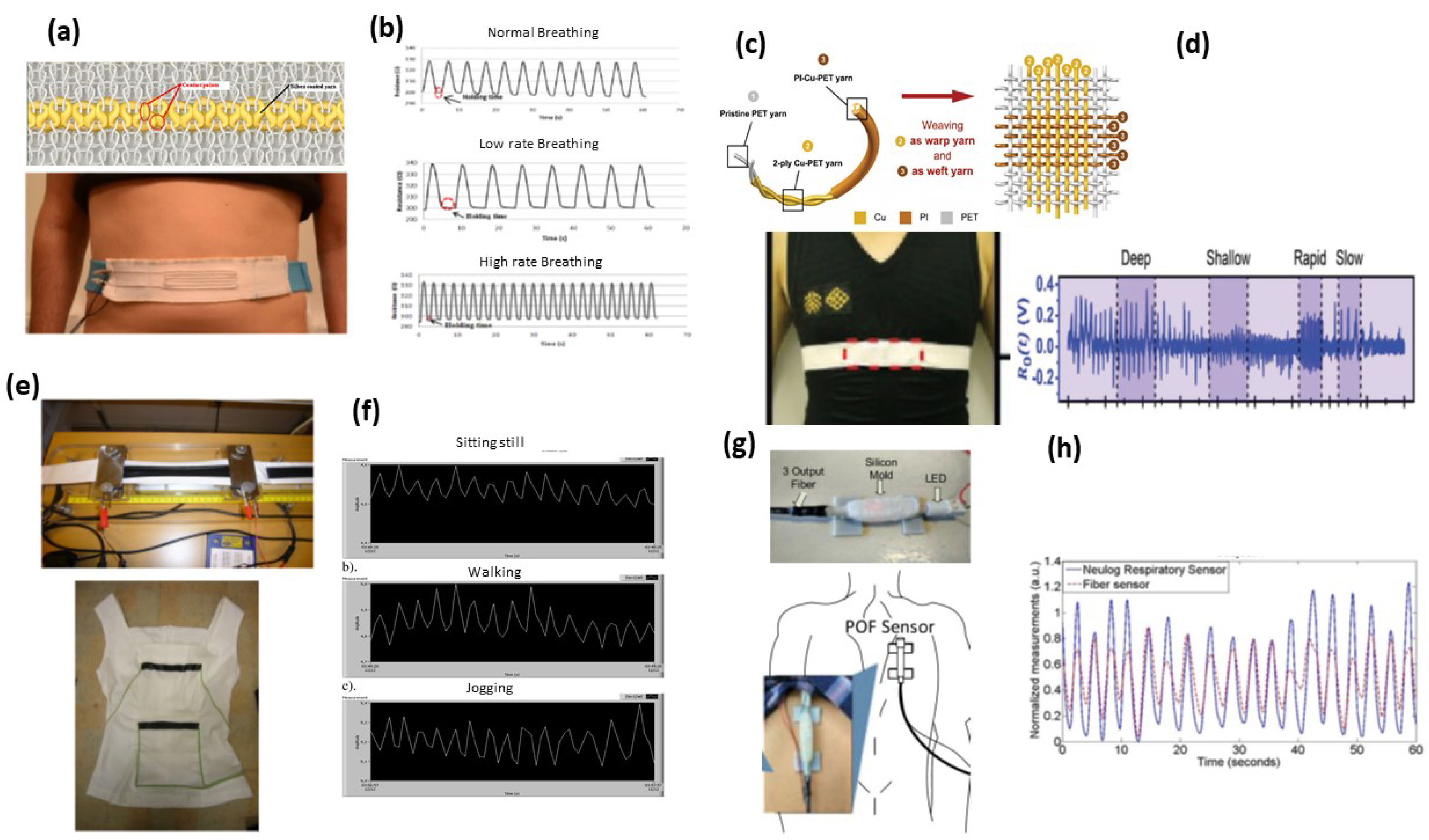
1.1. Smart Textile Biosensors and Physical Signals

Many research projects are dedicated to exploring and developing smart textiles for medicine and healthcare [3]. Wearable sensors can measure several physiological signals/parameters as well as activities. Nowadays, telemedicine is improving personal health care thanks to the development of wearable monitoring system. Indeed, wearable devices allow physiological signals to be continuously monitored during normal daily activities. For example, a patient with chronic diseases, pulmonary or heart problems, will continuously and simply monitor their health and send updates to their physician through the Internet. This can overcome the problem of infrequent clinical visits that can only provide a brief window into the physiological status of the patient. Biosensors integrated into textiles have been used for electrocardiogram (ECG) [7], electromyography (EMG) [8], and electroencephalography (EEG) [9,10,11]. Textile with integrated luminescent elements for biophotonic sensing [12], conductive yarn for activity sensing [1], thermocouples for temperature sensing, along with shape-, strain-, and movement-sensitive elements have been demonstrated [13,14]. The physiological signals measured with wearable sensors need a two-stage communication to transmit the data to the remote healthcare server. In the first stage, a short-range communication protocol is employed to transmit the measured data to a nearest gateway, such as smartphone, computer, custom-designed field-programmable gate array (FPGA), or a microcontroller-based processing board. The gateway is responsible for advanced data processing, display, and the next long range communication stage, where the processed signal is transmitted to a distant server placed in a healthcare facility. The data can be transmitted over the Internet or cellular communication network such as general packet radio service (GPRS), 3G/4G, high speed packet access (HSPA), and Long-Term Evolution (LTE) services [15,16,17]. The general overview of the remote health monitoring system is presented in Figure 1.
Breathing (or respiration) is an important physiological task in living organisms. Breathing rate (BR) is a vital sign used to monitor the progression of illness and an abnormal BR is an important indicator of serious illness. Variation in BR can be used to predict potentially serious clinical events such as heart attack [18,19]. For example, using changes in BR measurements, patients could have been identified as high risk up to 24 h before the event with 95.5 % confidence [20]. BR monitoring devices are separated into two categories: contact and non-contact sensors. In contact BR monitoring sensor, a direct physical contact with the body is needed. However, in non-contact monitoring sensor, the BR is measured without making contact with the subject’s body [21]. The most popular contact-based approach to derive the BR is from the ECG signal [22]. The ECG measurements have been performed using different techniques such as conductive textile patches [23], and piezoelectric transducer [24]. However, these solutions require electrodes that should be securely attached to the user’s body, which causes certain discomfort during long term use. Consequently, the contactless approach for BR monitoring is highly suggested.
Textile based sensing is an important alternative which provides a more conformable and user friendly approach for respiratory monitoring. The experimental results show that a simple sensor consisting of conductive filament yarns can be used to monitor human breathing activity [25]. These types of sensors are integrated into textile by different methods [26]. Weft-Knitted Strain Sensor made from silver coated nylon was used to fabricate a respiratory belt, which can be worn around the chest or abdomen to monitor breathing rate (Figure 2a,b) [27]. Smart textile based on triboelectric nanogenerators (t-TENGs) [28] was made by direct weaving of Cu-coated polyethylene terephthalate (Cu-PET) warp yarns and polyimide (PI)-coated Cu-PET (PI-Cu-PET) weft, and fabricated a chest strap that can monitor respiration rate and detect changes in the respiration patterns (Figure 2c,d). Conductive silicone was used by Guo et al. [29] to fabricate straps located on the chest and abdomen (Figure 2e,f). Flexible polymer optical fibers (POFs) based sensor have been used previously for breath monitoring [30,31,32]. The POF-based sensors present some advantages such as the absence of electrical interference, and good flexibility [33]. More recently, Wern et al. [34] integrated into a carrier fabric highly flexible POFs that react to applied pressure to form a wearable sensing system (Figure 2g,h). Other types of optical fiber that have been implemented in the wearable sensor include: fiber Bragg grating (FBG) [35], macro-bending of single-mode fiber [36], and notched side-ablated POF on a fabric substrate [37]. Actually, non-contact breath monitoring methods are not widely used by medical professionals due to several reasons related to patient comfort and safety, electromagnetic interference with existing medical equipment, and complexity of use.

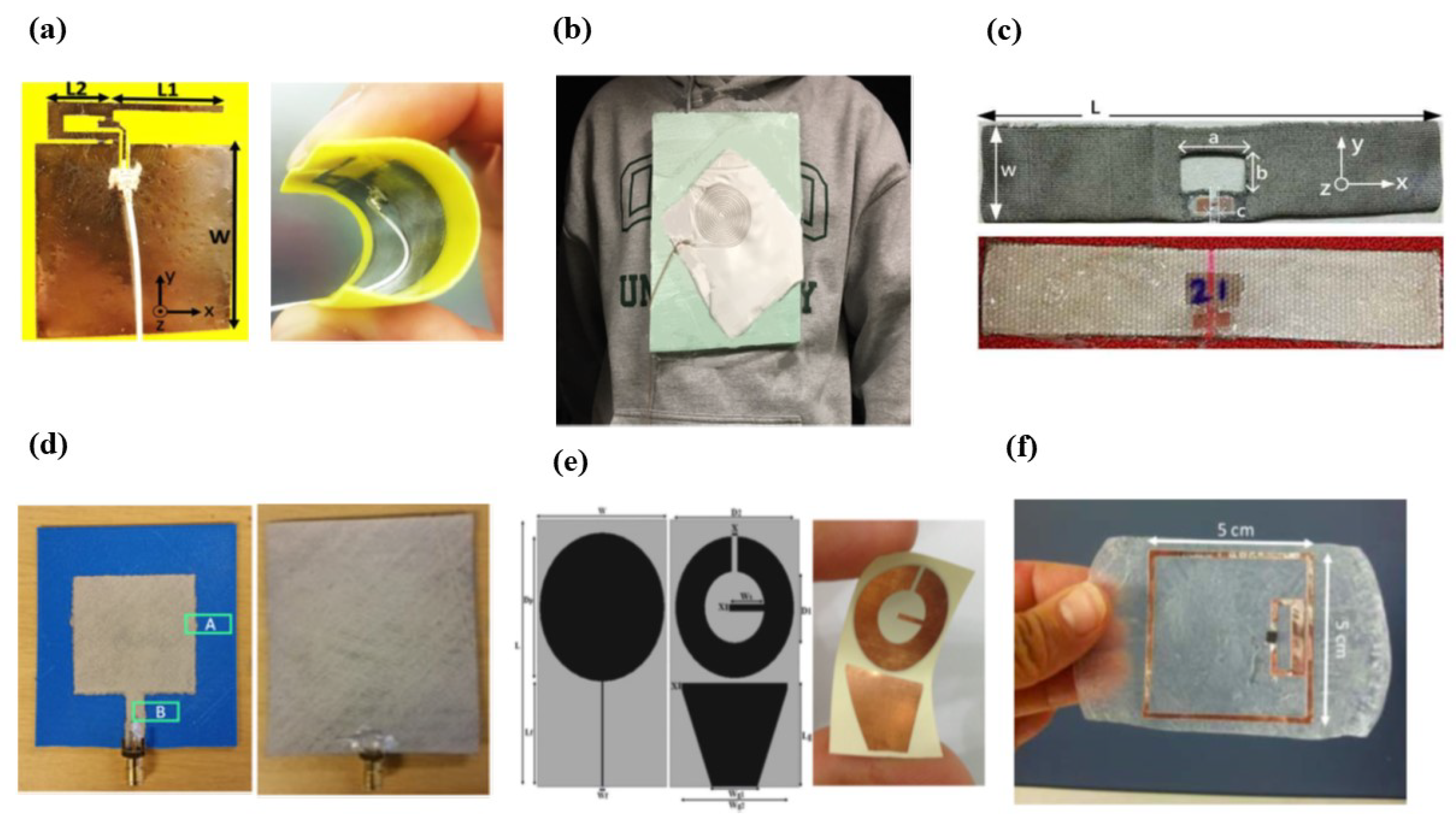
1.2. Wearable Antenna

For most applications of wearable sensors, wireless connectivity is one of the most critical requirements as it eliminates all the mobility restrictions of a tethered communication system [38]. Antenna is the system component enabling this important feature. For IoT applications, embedding antennas into clothing makes the garments become a smart interface for the interaction between the user and the network. The wearable antennas should be thin, robust, lightweight, and resistant to washing cycles and daily usage and, moreover, must be low cost for manufacturing and commercializing [39]. Several antenna designs have been proposed for medical applications in the industrial, scientific and medical (ISM) and Ultra High Frequency (UHF) bands. Karimi et al. [40] fabricated a modified inverted-F antenna (Figure 3a), inkjet printed directly on the fabric using silver nanoparticle ink with a frequency radiating at 2.45 GHz. With the rapid progress on the fabrication of conductive textile, silver yarn was used to create a spiral antenna (Figure 3b) for a system that senses heart rate, fall detection and measures ambient temperature [41]. Textile-based antenna for wearable UHF radio frequency identification (RFID) tags (Figure 3c) were fabricated by patterning of silver-plated fabric and brush-painting of silver ink on cotton fabric, and their performances after recurrent washing were studied [42]. The proof-of-concept of the fabrication and performance analysis of a flexible and stretchable patch square shape antenna on a 3-D printed substrate (Figure 3d) was presented by Rizwan et al. [43]. Using lithography process, flexible microstrip-fed ultra-wide band monopole antenna and ground was made up of copper on flexible substrate (Figure 3e) with a resonance frequency at 7.8 GHz was presented by Zahran et al. [44]. Advances in material science and the use of flexible material in skin mounted devices gave rise to epidermal UHF RFID sensors technology [45]. A Polycinyl alcohol/xyloglucan-based (PVA/XG) hydrogel featuring thin film copper antenna was fabricated (Figure 3f), and used for human skin temperature sensing and drugs delivery [46].
The developed wearable antennas are mostly planar, specifically microstrip patch antennas, because they mainly radiate perpendicularly to the planar structure and also their ground plane efficiently shields the human body. However, the efficiency and the bandwidth of patch antennas are directly proportional to the substrate thickness, and generally thicker substrate (6–7 mm) is preferred [47]. In addition, it has been demonstrated that the ability of the textile fibers to absorb moisture affects significantly the performances and reduces the operating frequency and bandwidth of the patch antennas [47,48], while patch antennas produced by inkjet-printing technique are prone to damage, operating frequency shifts, and losses due to compressing and tensioning of the conducting ink surface. The design of epidermal antenna sensors is challenging as its characteristics are directly affected by the human body tissue [49]. Furthermore, the thickness of the material and its characteristics impact the gain, return loss, and the size of the antenna, along with the impedance matching which is crucial in particular when the antenna is connected to biosensing devices and RFID chips if used within RFID tags [50].
Major progress has been achieved to improve the performance of the wearable antennas presented above. Nonetheless, further study and better characterization may still offer relevant improvements to their design and to the optimization of their behavior for technology acceptance.
With the recent development in material sciences, the ability to integrate distinct functional elements into a single device structure enabled the design of systems with higher-level functionality. Several electronic devices were achieved based on multimaterial fibers integrated within a textile host for acoustic and thermal applications, optical sensing, and RF detection [51,52,53,54]. In this paper, a new generation of wearable antennas based on a functionalized fibers featuring a combination of hollow-core glass, polymer, and metal layers in a well-defined geometry are presented. The mechanical properties of such multimaterial fibers allow them to be integrated into textiles using classical industrial weaving process and make them essentially indistinguishable from the textile host, thus preserving user-comfort of the traditional garments. First, multimeterial fiber antennas in dipole, loop and spiral shapes were fabricated, and then characterized in terms of return loss ( S 11 ), gain and radiation pattern to access its performance to determine its suitability to 2.4 GHz for the short range wireless network communication. The 2.4 GHz operating frequency was chosen for compatibility with well-known WiFi and Bluetooth protocol. The fiber antenna performances in different environmental conditions, such as on a human body, under physical stresses, under direct water application, and the ability to withstand multiple washing cycles with hydrophobic coating is presented. A first prototype of a smart textile featuring a spiral fiber antenna placed on the chest level for human breath detection is also presented. This is made possible by measuring the central frequency shifts of the antenna caused by the chest movement, with an off the shelf vector network analyzer (VNA). A new smart textile prototype based on wireless communication at 2.4 GHz is developed. It is composed of a stretchable T-shirt featuring a spiral shape multimaterial fiber antenna sensor and a base station. We demonstrate that the breathing pattern can be acquired wirelessly from the RSSI (Received Signal Strength Indicator) data via standard Bluetooth protocol using the designed platform. Indeed, when a person wearing the T-shirt starts breathing, the antenna shape changes and so does the resonance frequency and the transmitted signal strength. We successfully recorded breathing signals of a female volunteer and a male volunteer standing up in front of the base station using the same sensor despite the difference in the chest anatomy. Breathing frequencies of 0.3 Hz and 0.5 Hz were obtained leading to a breathing rate of 21 breaths per minutes (bpm) and 30 bpm, respectively.

2. Smart Textile Based on Multimaterial Fiber Antenna: Design and Fabrication

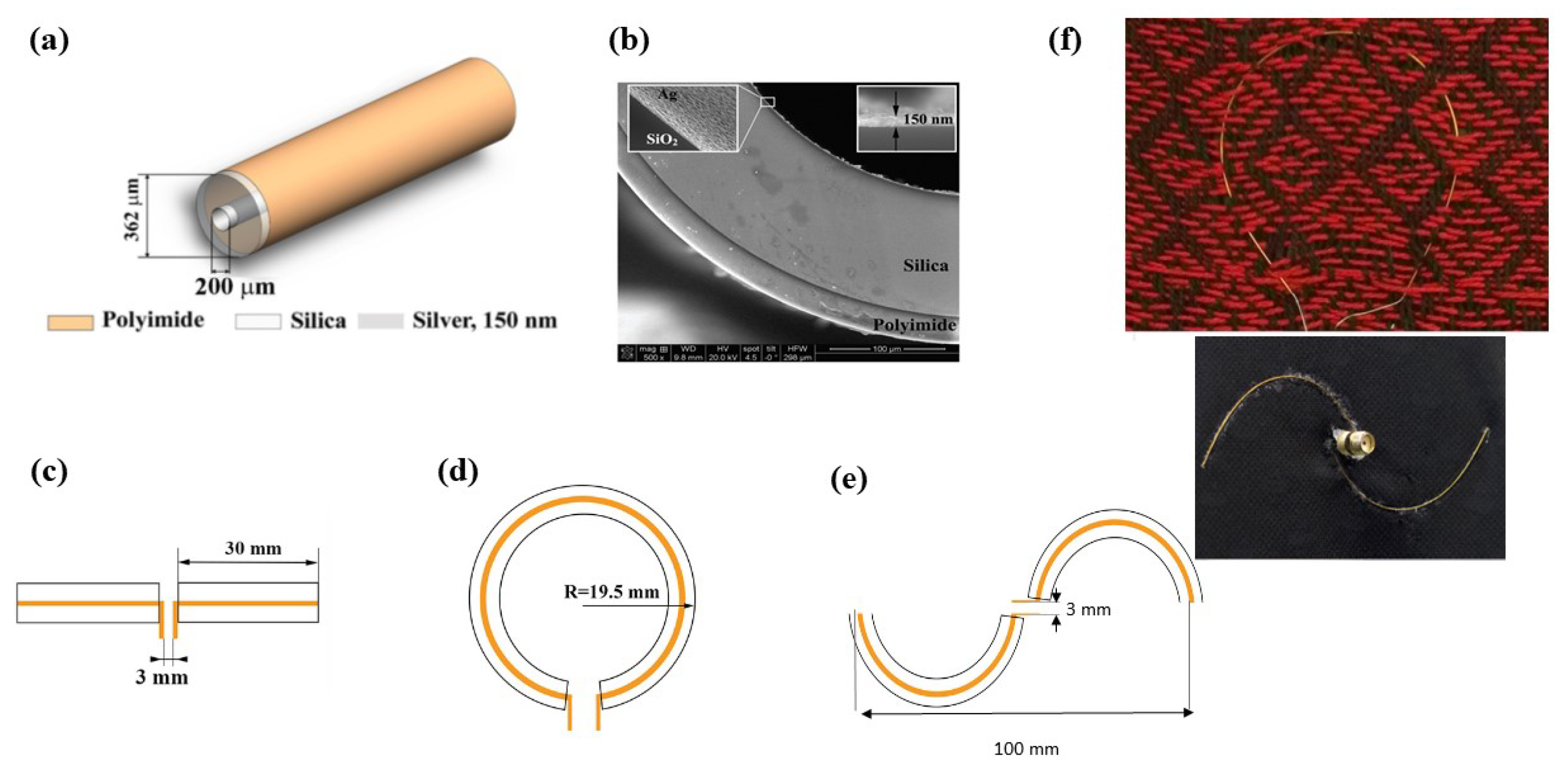
2.1. Fabrication of the Fiber Antenna

Fiber antennas consisted of metal-glass-polymer fiber composites. They were fabricated using hollow-core silica fibers (available commercially at Polymicro Technologies, Phoenix, AZ, USA) with an inner radius of 100 μ m and outer radius of 181 μ m, covered with an 18 μ m thick polyimide layer (Figure 4a). Silver thin layers were deposited in the inner surface of the hollow-core fiber using a redox chemical reaction [55]. The reaction consists in the precipitation of an aqueous solution composed of a mixture of silver nitrate (AgNO 3 ), potassium hydroxide (KOH), dextrose (C 6 H 12 O 6 ), and ammonium hydroxide (NH 4 OH), injected into the fiber’s hollow core. Using the scanning electron microscope (SEM) images, the inner silver coating had the thickness of 150 ± 30 nm (Figure 4b). The measured electrical dc resistivity of 3.8 ± 1 Ω /cm for the inner silver conductor along with the geometry of the structure of the antenna (Figure 4c–e) provided a good electrical matching to the standard 50 Ω impedance of the RF components, while the external polyimide coating provided long-term protection against the heat/humidity in the environment. Using the conductive multimaterial fiber, we have fabricated the most efficient and simplest designed antennas for 2.4 GHz operating frequency: center-fed half-wave linear dipole (Figure 4c), loop (Figure 4d), and a half-turn Archimedean spiral shape (Figure 4e). Typical dipole antenna consists of a pair of tubular conductors aligned in tandem so that there is a small feeding gap at the center, the length of half wavelength dipole is given by l = λ / 2 at 2.4 GHz equals to 61 mm. Thus, two 30 mm fibers were used, as can be seen in the dipole inset in Figure 4c. Loop antenna becomes resonant as the perimeter of the loop, p, approaches one wavelength in size p = 122 mm which corresponds to a radius of 19.5 mm, as shown in Figure 4d. In this case, single piece of multimaterial fiber was used. Half-turn Archimedean spiral is a special case of the dipole antenna with λ /2 at 2.4 GHz equals to 10 cm fabricated using two 50 mm long fibers, as shown in Figure 4e. As it is known from the antenna theory [56], operating frequency of the dipole and loop antennas can be adjusted for particular applications simply by varying their length.

2.2. Textile Integration

Two different methods to integrate the antennas into textile have been used. The first one was a computerized loom (Little Weaver from AVL Looms Inc., Chico, CA, USA), with 40 cm weaving width [57]. The fiber antennas themselves represented only a few substitution threads in the fabric and their flexibility made them unobtrusive enough to be essentially indistinguishable from the textile host. An example of a loop antenna integrated into textile is shown in Figure 4f (top). The fibers withstood weaving process, textile manipulation, and heat/humidity (i.e., + 60 C temperature and 80 % relative humidity for 96 h) tests without any damage or performance losses [53,54,57]. The second method was to manually sew the antenna onto the textile and fix the ends using cyanoacrylate glue, as shown in Figure 4f (bottom).

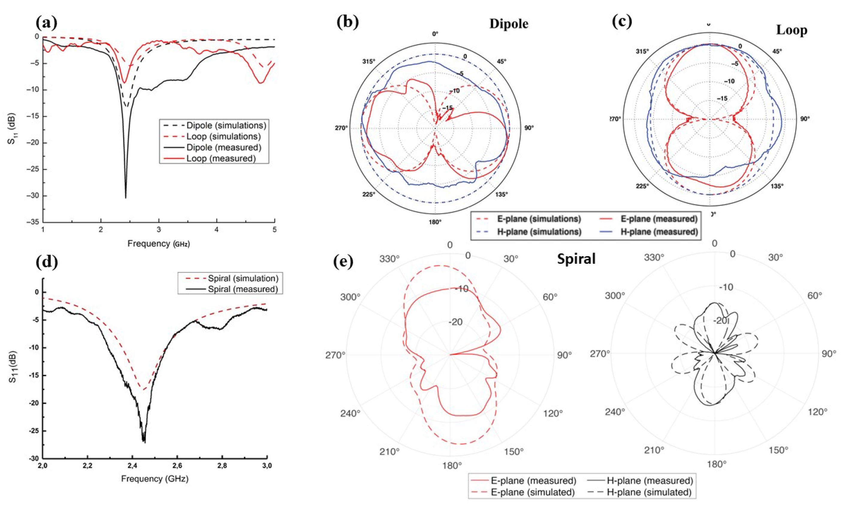
3. Emissive Properties of the Fiber Antenna in Free Space

The emissive properties of the designed antennas in terms of return loss ( S 11 ), gain (efficiency), and radiation pattern, were characterized experimentally and numerically using ANSYS HFSS software.

3.1. Return Loss

The key parameters that describe the antenna resonance frequency are the S-parameters, and more specifically S 11 . The textile integrated antennas were connected to an SMA connector by soldering a tin-coated copper wire (127 μ m in diameter) inserted through the inner hollow core. The frequency shift and the return loss S 11 of the antenna were continuously measured using a VNA (HP Agilent 8722ES, Santa Clara, CA, USA). A 50 Ω coaxial cable was used to connect the VNA and the SMA connector. Measured and simulated S 11 in free space are shown in Figure 5a for linear dipole and loop antenna, and in Figure 5d for spiral antenna. From these figures, we can observe that both experimental and numerical results are in a good agreement, and the operating frequency of the designed antennas is at 2.4 GHz.
No difference in terms of return loss S 11 was observed when the antennas were integrated into a cotton textile or into a stretchable textile (mainly made of 90% of polyester). This could be explained by the fact that the dielectric permittivity of the cotton and the polyester materials are very close, and were measured at ϵ r = 2.077 for cotton, and ϵ r = 2.122 for polyester [58].

3.2. Gain

The efficiency of an antenna is related to its gain and directivity. It is defined as the power radiated relative to the power delivered to the antenna. Textile antenna gain measurements were conducted using the technique based on well-known Friis equation approach [59] and described in details in the previous work [57]. The gain value is determined using the following equation:
| S 21 | 2 = ( 1 | S 11 | 2 ) ( 1 | S 22 | 2 ) G T G R ( c 4 π R f )
where G T and G R correspond to the gain and S 11 and S 22 are the return loss of the transmitting and the receiving antennas, respectively. The S 21 scattering parameters represents the power transmitted from one antenna to the other at certain frequency f, and c is the speed of light. In this case, an Aaronia HyperLog 7060 antenna (Aaronia USA, Seneca, SC, USA) with a known gain, G T , was used for transmission, and the textile antennas under test as the far field receiver. The transmitter and receiver antennas were connected to a VNA. The measurements were performed for the line-of-sight transmission in an unobstructed lab environment over a distance R = 162 cm and at 100 cm high above the ground, with an RF absorber placed on the ground to eliminate multipath propagation.
This approach provided gain measurements of 3.34 dBi for the linear dipole and spiral textile antenna, and 1.76 dBi for the loop textile antenna. Both linear dipole and spiral antennas’ gains are comparable to the 3.45 dBi gain of a common rubber ducky antenna manufactured by Bplus Technology Co. Ltd. (Taipei, Taiwan).

3.3. Radiation Pattern

The radiation patterns of the textile antennas were measured in an anechoic chamber using the Aaronia HyperLOG-7060 antenna and a tunable signal generator on the transmission side, while the textile samples were kept fixed on a dielectric holder and acted as far-field receivers [57]. Linear dipole (Figure 5b), and loop (Figure 5c) textile antennas exhibit patterns in E and H radiation planes in agreement with numerical simulations. The radiation pattern of the textile integrated spiral antenna is more complicated and demonstrates a combination of the classical half-wave dipole and multiple-turns spiral radiation pattern, as shown in Figure 5e [60].

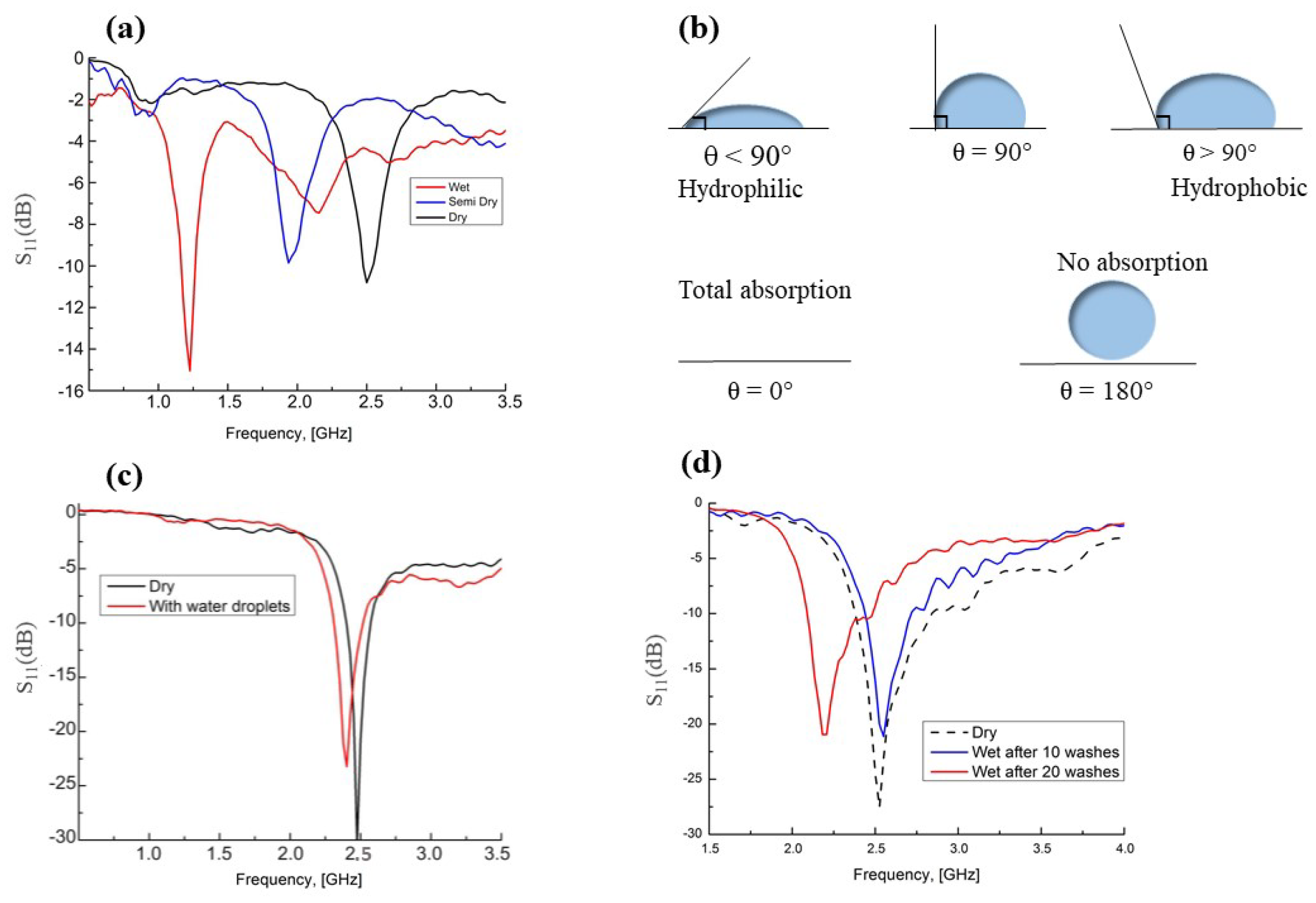
4. RF Smart Textile in Different Environmental Conditions

As described in Section 1.2, the performance and reliability of the existing wearable antenna are affected by the environmental conditions, such as moisture in the textile, and mechanical stress. In the case of multimterial fiber antenna, the advantage relies on the chemically stable, mechanically strong, and thermally robust cladding materials used to shield efficiently the embedded conductive sliver film within the fibers from the environmental perturbations such as water, detergent, chemical exposure, and high temperatures (High T g for both silica glass and polymer). Nevertheless, the multimaterial fiber antenna performances need to be tested in the presence of lossy dielectric medium (which could be caused, e.g., by rain, washing or sweat) and against any external deformations.

4.1. Influence of Moisture

Textiles with integrated fiber antennas were tested under direct water application [61]. When the textile samples get wet, a shift of about 1.27 GHz of the operating frequency was observed, as revealed from the return loss measurements shown in (Figure 6a). As the smart textile dries out, the operating frequency returns to its original value and the textile antenna regains its performance. The shift observed in this experiment is related to the amount of water used, and can vary from a few MHz to reach easily a large value (≈1.27 GHz). In this case, the fiber antennas become nonoperational in the ISM band, which is clearly not desirable, especially in the case of medical applications. As the performances of any antenna are affected in the vicinity of any conductive medium [62], the observed frequency shift effect in the presence of a lossy dielectric medium is not surprising as the dielectric constant of water, ϵ r = 80.1 for water at 20 C [63], significantly different than that of the air ( ϵ r = 1) in the near-field of the radiator. Thus, the influence of moisture on the antenna properties could be significant, meaning that, for practical uses, the antenna needs to be protected, for example by coating with a waterproof polymer or using hydrophobic textiles rather than the conventional fabrics [64].

4.2. Effect of Superhydrophobic Coating

Water is a polar molecule and its interaction with a physical surface can be classified as attractive or repulsive depending on the surface material composition. A material is called hydrophilic when its surface attracts a water droplet, and the latter tends to stick to the surface more than it sticks to itself, and will have a contact angle (CA) less than 90 . However, a material is called hydrophobic when the water droplet has a tendency to stick to itself more than it sticks to the surface, and, in this case, the water will bead up with a CA greater than 90 . In addition, there are two particular cases worth to mention. When a water droplet is completely absorbed by a surface, the latter becomes totally wet and the CA is ≈ 0 , but, when the surface is not wet in the presence of water (no absorption), then the CA is ≈ 180 . The four interactions between a water droplet and a surface are schematically described in Figure 6b.
A superhydrophobic coating (Ultra Ever Dry (UED), UltraTech International, Inc., Jacksonville, FL, USA) with CA 160 was applied on the multimaterial fiber antenna using a small aerosol sprayer and left to dry under ambient conditions. A second type of a spray-on coating textile shield (Drywired, Los Angelos, CA, USA) was applied on the textile. Coating the textile host is performed for several reasons: (1) to prevent the water from being absorbed by the textile; (2) to give a better protection; and (3) to preserve the antenna performance.
With the UED and textile shield superhydrophobic coatings being applied on the smart textile, the emissive performance of the fiber antenna was tested in terms of return loss ( S 11 ). Under direct water application, a minor frequency shift of 0.073 GHz was observed as shown in Figure 6c, while without coating it could be as large as 1.27 GHz as shown previously (Figure 6a). Such small frequency shift allows the fiber antenna to stay operational and to maintain an uninterrupted connection in the 2.4–2.5 GHz ISM band.

4.3. Effect of Machine-Washing

Textile featuring multimaterial fiber antenna covered with hydrophobic coating was first washed in 1 L of deionized water with 1 mL of a household detergent at 40 C during 15 min using a heated magnetic stirring plate, then thoroughly rinsed in a hot tap water at 60 C and dried by hot air (≈ 70 C) flow [61]. The performances of the coated antenna were determined by measuring the return loss after 10 and 20 washing cycles. The corresponding results are shown in Figure 6d. After 10 washes, the operating frequency remains very close to the frequency of the dry antenna. However, after 20 washing cycles, the connection with the antenna at 2.4 GHz is interrupted since the operating frequency shift becomes noticeably large 350 MHz. In practice, the coating should be re-applied after 10–15 washes to maintain stable antenna performance. No difference in terms of hydrophobicity was noticed between a textile sample coated for the first time and a textile sample with restored coating after consecutive application of the coating.

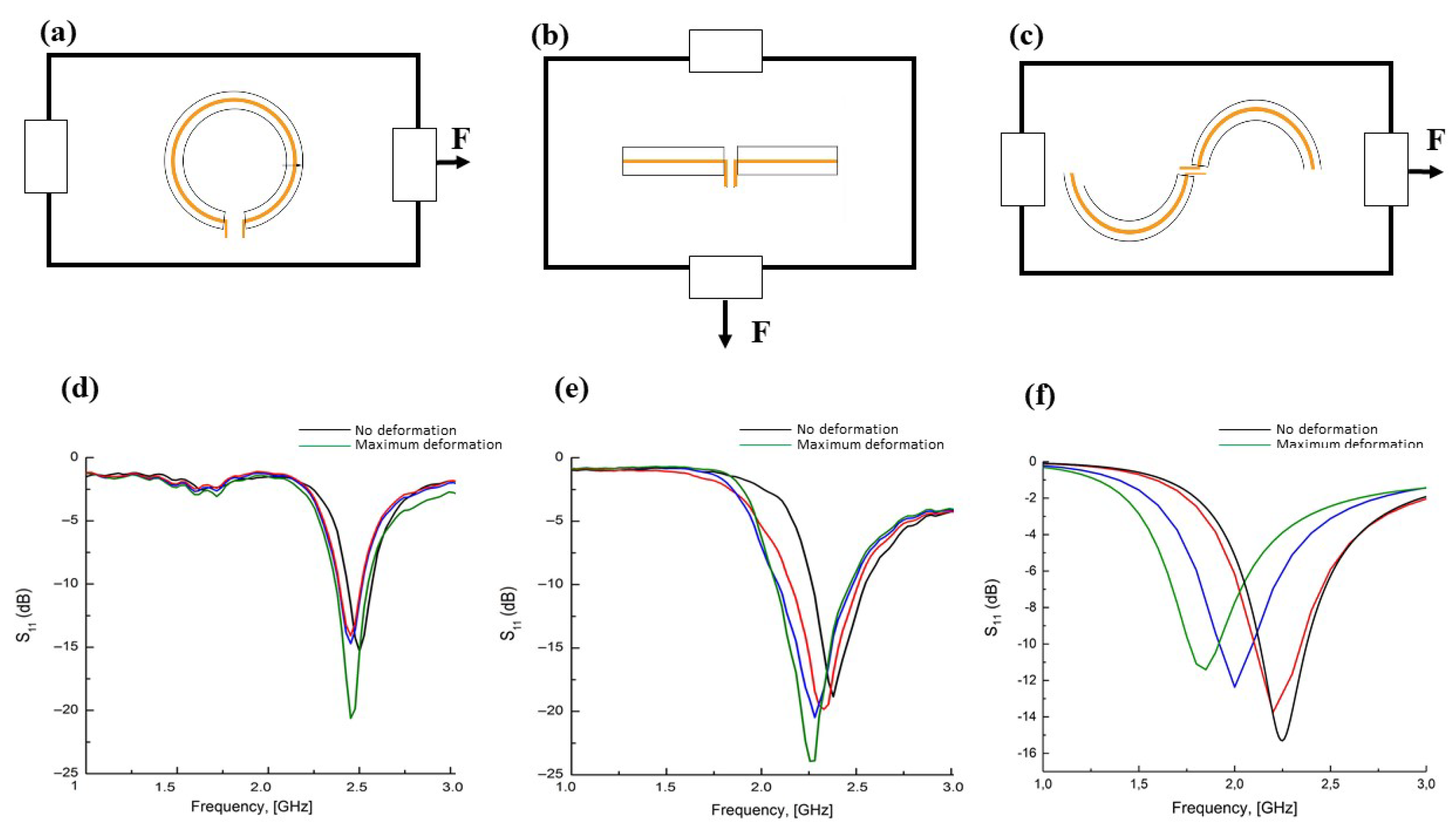
4.4. Influence of Conductive Medium: Frequency Shifts and Mechanical Stress

It is well known that the performance of an antenna is affected by the proximity of any conductive medium such as human body [62]. Problems of frequency shifting and power dissipation have been extensively studied in the context of implantable antennas [65]. The human body is a very complex and inhomogeneous layered structure comprising muscle, fat, and skin tissues, each exhibiting different dielectric properties that may vary considerably from one person to the other [66]. A variety of physical and numerical models, also known as “phantoms”, or simulated human body (SHB) have been proposed [67,68] for this study. A one-layer phantom representing muscle tissue was used, and its composition was chosen according to the considerations presented in [66] for 2.4 GHz frequency. More specifically, the physical body phantom consisted of 60% (by weight) deionized water, 40% sugar, and 2 g gelatin per 100 mL [60]. Along with the body phantom, a SHB model was implemented in the ANSYS environment [69] including the human body dielectric properties [68]. The model is a simplified version of the exterior human body where it does not contain any organs. For muscle at 2.45 GHz, the conductivity is equal to 1.73 S/m, and the relative permittivity is 52.73, with a mass density of 1040 Kg/m 3 [70,71]. With these models and without applying any hydrophobic coatings on neither the textile nor the antennas, the loop antenna exhibited a significant central frequency shift of about 200 MHz, while the dipole and the spiral textile antenna exhibited a smaller frequency shift of about 16 and 72 MHz, respectively. In the proximity of tissues, the resonance frequencies are detuned downwards according to perturbation theory [72]. As shown in a recent study [73], below ≈1 mm distance between the antenna and the body, the dominating mechanism is caused by the parasitic inductance with very low contribution from the capacitive coupling. For example, for the fiber loop antenna the measured impedance ( Z l o o p = 60.4 + j 8.26 ) has a higher inductive component comparing to the one in the dipole antenna impedance ( Z d i p o l e = 52.5 + j 0.14 ) and the spiral antenna ( Z s p i r a l = 46.09 j 16 ), which increases in the proximity of the phantom, and demonstrates a greater frequency shift than the fiber dipole antenna.
When textile fiber antenna is mounted on a body, its geometry is subject to significant deformations caused by the body shape. The antenna deformation causes changes to the RF emissive properties of the smart textile [54,57,64]. Therefore, the effect of mechanical deformations needs to be quantified for the multimaterial fiber antennas. Investigation of the frequency response as a function of stretching deformation have been performed for dipole, loop and spiral fiber antennas [57,60,68]. The experiments were realized by applying surface tensile stress on the textile with a constant increment [57,60,68], and measure the frequency shifts from the return loss curve. The direction of the applied deformation with respect to the orientation of the antenna is shown in Figure 7a–c. For the loop textile antenna, Figure 7d shows a constant emission frequency even under highest deformation. This could be explained by the fact that the length of the loop antenna remains constant under stretching loads, while the dipole textile antenna exhibited significant frequency shifts of ≥ 150 MHz, as shown in Figure 7e, due to the dipole folding into a V-shape under increasing stretch loads. The stretching deformation applied to the spiral antenna results in a larger frequency shift of 360 MHz, as shown in Figure 7f, compared to the loop and dipole antennas. It is worth noting that the stretching deformation applied to the spiral antenna does not cause any elongation to the antenna, and only the radii of the spiral fiber changes [68]. This experiment demonstrates that the spiral antenna geometry is more flexible than the dipole and loop antennas, making it more vulnerable to any physical stresses applied in different directions.

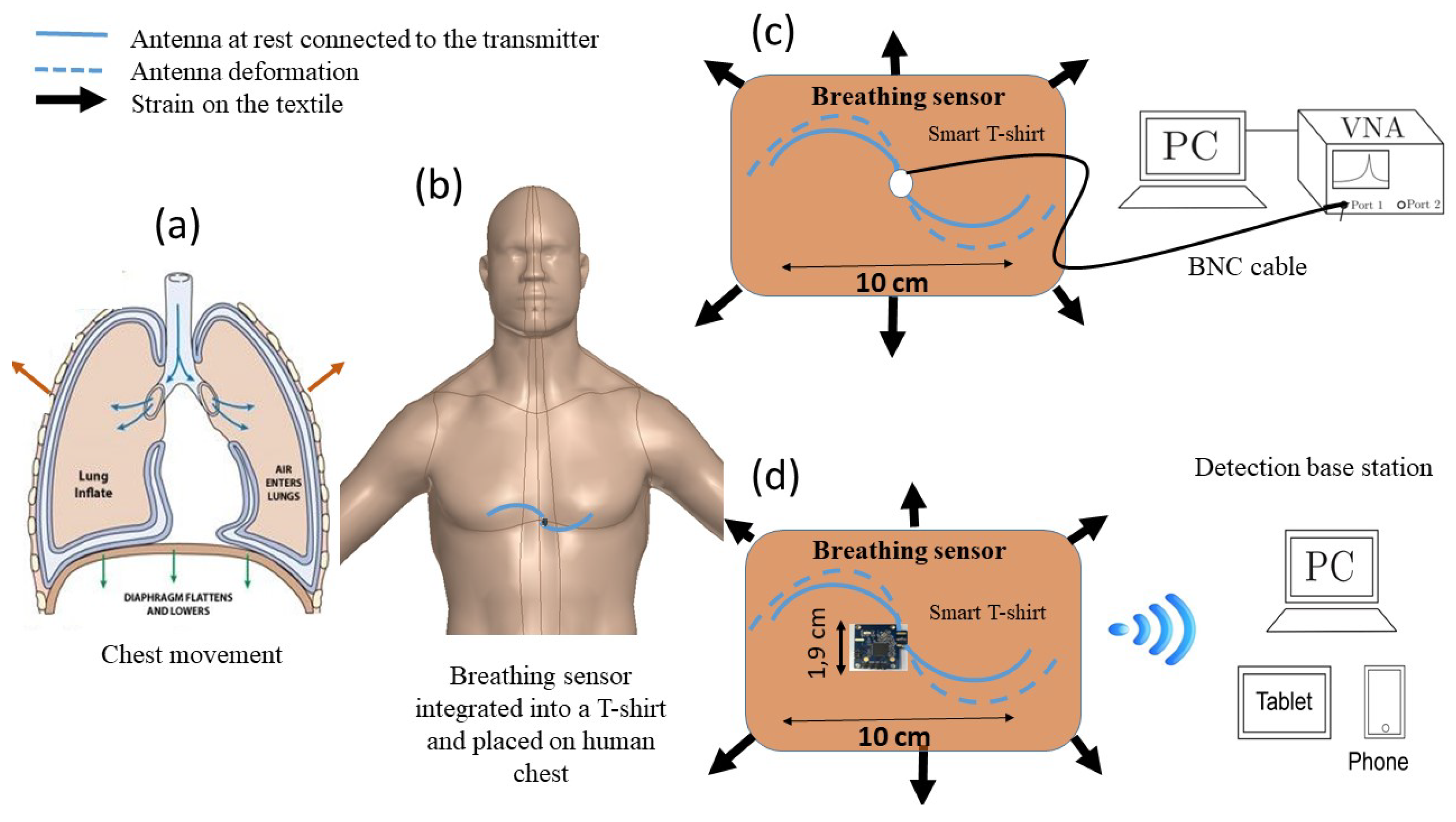
5. Multimaterial Fiber Antenna for Real Time Breath Detection

5.1. Breath Detection Mechanism

A Simplified air volume change in the lungs during breathing is shown in Figure 8a. During respiration, human chest and abdomen are subject to a mechanical deformation and dielectric properties modification caused by the air exchange between the lungs and the external environment. The inhalation phase is primarily due to the contraction of the human diaphragm. The contraction of the diaphragm due to the enlargement of the thoracic cavity causes the intra-thoracic pressure to fall. The latter induces lung expansion due to inspiration. In the exhalation phase, the diaphragm and inter-costal muscles relax. Consequently, the chest and abdomen return to the rest position. The tidal volume during normal breathing is typically estimated as 7 mL per kg of body mass, which, in the case of 25–34-year-old male patient, is equivalent to the chest circumference expansion of 7.37 cm [74]. During inhalation or exhalation, the dielectric properties of the whole torso are noticeably changed. For example, the relative permittivity, ϵ r , of the inflated lungs at 2.45 GHz equals to 20.51 while the relative permittivity of deflated lungs at the same frequency equals to 48.45 according to Gabriel [75]. However, a possible way to detect breathing is to have a high sensitive sensor capable of detecting simultaneously the physical deformation and the change in dielectric properties of the medium. As discussed above in Section 4.4, the emissive properties of multi-material fiber antennas are affected by these two mechanisms, in particular, the spiral shape fiber antenna showed a higher sensitivity to the mechanical deformation, along with a significant frequency shift in the vicinity of a body phantom. Consequently, the spiral fiber antenna could be used as a sensor to detect the human breathing [68].

5.2. Breath Detection Based on Frequency Shift Measurements

A spiral fiber antenna was integrated into a fitted T-shirt at the mid-chest position (Figure 8b), allowing the chest expansion to slightly stretch the antenna, as shown in Figure 8c. The operating frequency shift was continuously measured using a VNA connected to the antenna through an SMA connector by mean of a coaxial cable, as presented in Figure 8c. With this configuration, Guay et al. [60] performed a series of measurements to detect breathing of a volunteer asked to take four breaths, followed by one minute of relaxed, shallow breathing, and four more deep breaths. A frequency shift of 120 MHz was detected for deep breathing, while relaxing, shallow breathing led to smaller 4–15 MHz frequency shifts. These measurements validate the proposed respiration sensor based on multimaterial fibers in spiral shape arrangement integrated into a standard T-shirt for breath detection. Although these measurements seem to be very promising, the user’s comfort which is an important factor as discussed in the introduction needs to be addressed.
Received signal strength based breathing monitoring is emerging as an alternative non-contact technology. A wireless systems operating at a 2.4-GHz frequency to estimate the respiration rate has been presented recently [76,77,78,79], and showed limitation in term of detection accuracy and heavy mathematical treatments.

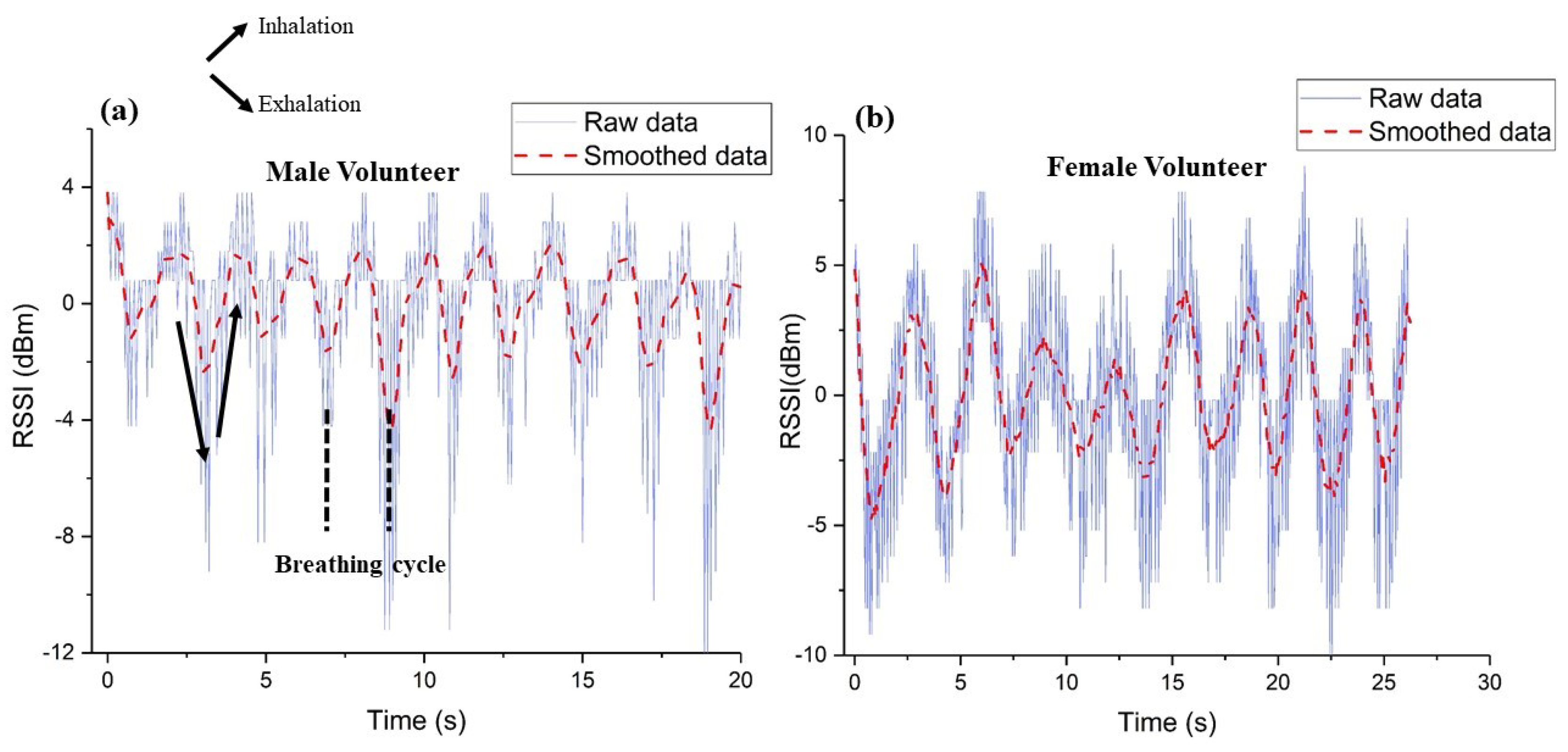
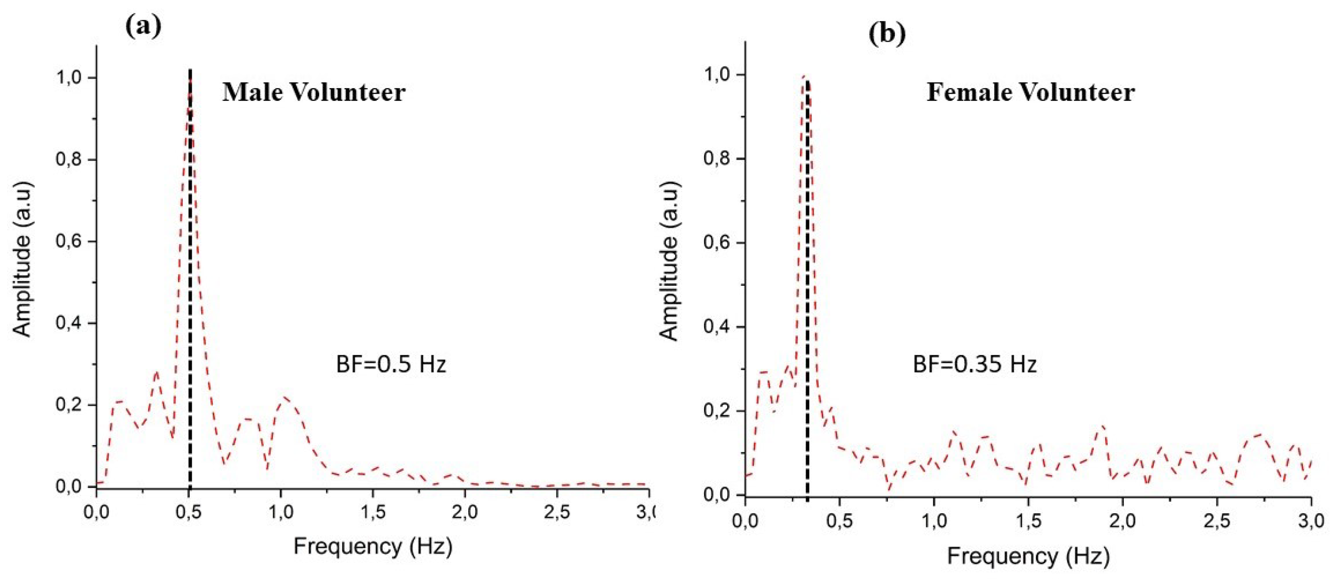
5.3. Breath Detection Based on RSSI Measurements

A new detection scheme based on the measurement of the power transmitted by the spiral antenna through a Bluetooth protocol was developed. The proposed portable platform to monitor the respiration is composed of four parts: a spiral fiber antenna integrated into a textile, a transmission module, an energy harvesting module, and a base station as described in Figure 8d. The breathing sensor made from a spiral antenna connected to a Bluetooth transmitter is placed at the mid-chest position, and during breath, the transmitted signal from the sensor is sensitive to strain caused by the chest movement, so it can be used for monitoring the breathing signal.
The transmission module is a Bluetooth transceiver (Nordic Semiconductors SoC nRF51822) transmitting and receiving at a band rate of 250 kbps, and acts as an advertising beacon on three channels following the Bluetooth Low Energy (BLE) protocol with a 2.4 GHz operating frequency over a narrow bandwidth of 80 MHz. The energy harvesting is achieved through BQ25570 chip (Texas Instruments, Dallas, TX, USA) connected simultaneously to two solar cells panel (1.2 V, 200 mW) and a small flexible rechargeable battery. The solar cells are connected to the rechargeable battery to recharge it when the battery voltage goes below 3 V until it reaches 4.3 V. The collected energy is 3 mW when the solar cell is closely and directly exposed to indoor light. The breathing pattern is extracted from the variation of the signal strength emitted at 2.4 GHz from the T-shirt’s sensor and detected using a home made base station [68].

Breathing Patterns

The breathing patterns were obtained with the help of a male volunteer and a female volunteer wearing the T-shirt with the spiral antenna integrated at the chest level, standing up at 1 m distance away from the base station. The sampling period was set to 20 Hz to measure the maximum breathing rate of 1.2 Hz, which satisfies the Shannon constraint. Data were first filtered using a band-pass filter with a cut-off frequency of 0.11–1.9 Hz. The center frequency of the filter was chosen with respect to the maximum and minimum breathing frequency expected from a human subject under normal conditions [68]. Breathing frequency (BF) was extracted from the treated signal using a fast-Fourier transform (FFT) to detect the dominant frequency.
In a first test, the male volunteer was asked to perform ten breaths to detect a correlation between the respiration and the received signal at the base station. The RSSI measurement together with the filtered signal are presented in Figure 9a. In this figure, the inhalation and the exhalation phases in each breathing cycle (BC) are clearly extracted. We can observe that the RSSI signal oscillates as the volunteer breathes, and the base station detects ten BCs during 20 s. The inhalation and the exhalation period is estimated to ≈2.3 s. The BF measurement obtained using FFT is shown in Figure 10 a with peak at ≈0.5 Hz, which corresponds to 30 bpm.
In the second test, the female volunteer was asked to perform nine regular breaths with the same sensor placed on the chest. The result is displayed in Figure 9b. Although the chest anatomy of a female is different from a male, the sensor detected accurately nine BCs within 26 s. From this measurement, the inhalation and the exhalation period is estimated to be ≈2.9 s, and the BF is measured at ≈0.35 Hz (Figure 10b), which corresponds to 21 bpm.
These results demonstrate that the previously reported method for contactless breath detection using frequency shift measurements can be implemented on a fully wireless portable platform. The unobtrusive integration of the multi-material fiber sensor into textile allows taking full advantage of the high user comfort associated with the traditional garments, which is important for particular medical applications, such as 24 h monitoring of newborns or elderly persons. A comprehensive comparison between the two platforms, their advantages and disadvantages, is summarized in Table 1.

6. Conclusions and Future Work

A new generation of wearable antennas for healthcare monitoring was fabricated by integrating polymer-glass-metal fiber composites into a well defined geometry. The mechanical properties of the fibers enable an easy integration of the antenna into textile using the classical weaving methods, thus leading to a development of new wireless communication platform. The RF emissive performance of the textile-integrated fiber loop, dipole and spiral antennas were characterized in terms of return loss, radiation pattern and gain, and found to be comparable to the commercial wireless router antennas, and suitable for short range wireless networks in the ISM band at 2.4 GHz. The environmental endurance of the proposed smart textile was characterized in terms of frequency shifts and return loss in the presence of moisture, and then enhanced by the application of superhydrophobic coatings (CA 150 ) on the fibers and the textiles. The water-repelling properties of the coating allowed a minimal frequency shift under direct water application, which means an uninterrupted connexion during application in the ISM band. In addition, the performance of the fiber antennas was not affected during repeated washing and drying up to 15 cycles. The advantage of the multimaterial composition of the antenna relies on the robust cladding materials used to shield efficiently the embedded conductive sliver film within the fibers from the environmental perturbations. The high flexibility of the multimaterial fiber antenna with spiral geometry increases the sensitivity of the antenna against physical deformation in the vicinity of a body phantom, and causes a significant shift to the operational frequency in comparison to the dipole and the loop antennas. A smart T-shirt prototype featuring a contactless and non-invasive multimaterial spiral fiber antenna placed on the middle of the human chest was fabricated for breath detection. This is made possible through the frequency shift of the antenna exhibited due to the lung volume change and textile stretching under the chest movement. Typical frequency shifts of 4–200 MHz were measured using off the shelf VNA instrument. To improve the user comfort, a wireless communication sensor was developed. The sensor is made from a multimaterial spiral fiber antenna connected to a Bluetooth transmitter. The human breath is recorded through the detection of the transmitted RSSI signal by mean of a base station. Breathing signals of a female and a male volunteer were successfully recorded with the same sensor, and a breathing rate of 0.35 Hz for the female and 0.5 Hz for the male were measured, leading to a breathing rate of 21 bpm and 30 bpm, respectively.
The goal of this work was to demonstrate the capability of the newly developed sensor to detect in real time the breathing patterns of a human and communicate the data via a Bluetooth protocol at 2.4 GHz to a base station. For medical applications, such as in situ diagnose of respiratory illnesses and monitor people suffering from asthma, sleep apnea or chronic obstructive pulmonary disease, it is important to validate our system. This could be done by a head-to-head comparison with gold standard equipments such as a spirometer or a pneumotachograph, which is the subject of our future work.

Author Contributions

All authors made substantial contributions to the study, including conception and design of the experiment as well as analysis and interpretation of data. In particular, M.R. designed the experiments, acquired and analyzed the experimental data, and wrote the article. M.K. developed the software for the wireless system, and performed numerical simulations. A.M. and Y.M. participated in the analysis and critical discussion of the obtained results. Y.M. revised and gave the final approval of the paper.

Acknowledgments

The authors would like to thank the fruitful contributions of the Canada Excellence Research Chair in Photonics Innovations, of the Canada Research Chair in Advanced Photonic Technologies for Communications, and of the Biomedical Microsystems Laboratory of Laval University. The authors also acknowledge financial support from the National Research Council of Canada (NSERC/discovery grant program) and CMC Microsystems for their technical and financial support related to ANSYS HFSS.

Conflicts of Interest

The authors declare no conflict of interest.

References

  1. Majumder, S.; Mondal, T.; Jamal Deen, M. Wearable Sensors for Remote Health Monitoring. Sensors 2016, 17, 130. [Google Scholar] [CrossRef] [PubMed]
  2. Langereis, G.R.; Bouwstra, S.; Chen, W. Sensors, Actuators and Computing Architecture Systems for Smart Textiles. In Smart Textiles for Protection; Chapman, R., Ed.; Woodhead: Cambridge, UK, 2012; Volume 1, pp. 190–213. [Google Scholar]
  3. Koncar, V. Introduction to smart textiles and their applications. In Smart Textiles and their Applications; A Volume in Woodhead Publishing Series in Textiles; Woodhead Publishing: Cambridge, UK, 2016; pp. 1–8. [Google Scholar]
  4. Morris, D.; Schazmann, B.; Wu, Y.; Coyle, S.; Brady, S.; Hayes, J.; Slater, C.; Fay, C.; Lau, K.T.; Wallace, G.; et al. Wearable Sensors for Monitoring Sports Performance and Training. In Proceedings of the 5th International Summer School and Symposium on Medical Devices and Biosensors, Hong Kong, China, 1–3 June 2008; pp. 121–124. [Google Scholar]
  5. Berzowska, J. Very slowly animating textiles: Shimmering flower. In Proceedings of the 31th International Conference on Computer Graphics and Interactive Techniques, Los Angeles, CA, USA, 8–12 August 2004. [Google Scholar]
  6. Nayak, R.; Wang, L.; Padhye, R. Electronic textiles for military personnel. In Smart Fabrics and Wearable Technology in Electronic Textiles; Woodhead Publishing: Cambridge, UK, 2015; pp. 239–256. [Google Scholar]
  7. Cheng, J.; Amft, O.; Lukowicz, P. Active capacitive sensing: Exploring a new wearable sensing modality for activity recognition. In Proceedings of the 8th International Conference on Pervasive Computing, Helsinki, Finland, 17–20 May 2010. [Google Scholar]
  8. Linz, T.; Gourmelon, L.; Langereis, G. Contactless EMG sensors embroidered onto textile. In Proceedings of the 4th International Workshop Wearable Implantable Body Sensor Netw, (BSN’07), Aachen, Germany, 26–28 March 2007; Volume 13, pp. 29–34. [Google Scholar]
  9. Lofhede, J.; Seoane, F.; Thordstein, M. Soft textile electrodes for EEG monitoring. In Proceedings of the 10th IEEE International Conference on Information Technology and Applications in Biomedicine (ITAB), Corfu, Greece, 2–5 November 2010; pp. 1–4. [Google Scholar]
  10. Lofhede, J.; Seoane, F.; Thordstein, M. Textile electrodes for EEG recording—A pilot study. Sensors 2012, 12, 16907–16919. [Google Scholar] [CrossRef] [PubMed]
  11. Chi, Y.M.; Cauwenberghs, G. Wireless non-contact EEG/ECG electrodes for body sensor networks. In Proceedings of the International Conference on Body Sensor Netw, (BSN’10), Singapore, 7–9 June 2010; pp. 297–301. [Google Scholar]
  12. Omenetto, F.; Kaplan, D.; Amsden, J.; Dal Negro, L. Silk Based Biophotonic Sensors. U.S. Patent US2013/0330710 A1, 12 December 2013. [Google Scholar]
  13. Lee, J.; Kwon, H.; Seo, J.; Shin, S.; Koo, J.H.; Pang, C.; Son, S.; Kim, J.H.; Jang, Y.H.; Kim, D.E.; et al. Conductive fiber-based ultrasensitive textile pressure sensor for wearable electronics. Adv. Mater. 2015, 27, 2433. [Google Scholar] [CrossRef] [PubMed]
  14. Kinkeldei, T.; Zysset, C.; Cherenack, K.; Troster, G. A textile integrated sensor system for monitoring humidity and temperature. In Proceedings of the Solid-State Sensors, Actuators and Microsystems, Beijing, China, 5–9 June 2011. [Google Scholar]
  15. Halonen, T.; Romero, J.; Melero, J. GSM, GPRS and EDGE Performance: Evolution towards 3G/UMTS; John Wiley and Sons: Hoboken, NJ, USA, 2002. [Google Scholar]
  16. Salkintzis, K. Mobile Internet: Enabling Technologies and Services; CRC Press: Boca Raton, FL, USA, 2004. [Google Scholar]
  17. Dahlman, E.; Parkvall, S.; Skold, J.; Beming, P. 3G Evolution: HSPA and LTE for Mobile Broadband; Academic Press: Cambridge, MA, USA, 2010. [Google Scholar]
  18. Fieselmann, J.F.; Hendryx, M.S.; Helms, C.M.; Wakefield, D.S. Respiratory rate predicts cardiopulmonary arrest for internal medicine patients. J. Gen. Intern. Med. 1993, 8, 354–360. [Google Scholar] [CrossRef] [PubMed]
  19. Subbe, C.P.; Davies, R.G.; Williams, E.; Rutherford, P.; Gemmell, L. Effect of introducing the Modified Early Warning score on clinical outcomes, cardiopulmonary arrests and intensive care utilisation in acute medical admissions. Anaesthesia 2003, 58, 797–802. [Google Scholar] [CrossRef] [PubMed]
  20. Cretikos, M.; Chen, J.; Hillman, K.; Bellomo, R.; Finfer, S.; Flabouris, A. The objective medical emergency team activation criteria: A case-control study. Resuscitation 2007, 73, 62–72. [Google Scholar] [CrossRef] [PubMed]
  21. Murthy, R.; Pavlidis, I.; Tsiamyrtzis, P. Touchless monitoring of breathing function. In Proceedings of the 26th Annual International Conference of the IEEE Engineering in Medicine and Biology Society, San Francisco, CA, USA, 1–5 September 2004; Volume 2, pp. 1196–1199. [Google Scholar]
  22. Boyle, J.; Bidargaddi, N.; Sarela, A.; Karunanithi, M. Automatic Detection of Respiration Rate From Ambulatory Single-Lead ECG. IEEE Trans. Inf. Technol. Biomed. 2009, 13, 890–896. [Google Scholar] [CrossRef] [PubMed]
  23. Lee, Y.-D.; Chung, W.-Y. Wireless Sensor Network Based Wearable Smart Shirt for Ubiquitous Health and Activity Monitoring. Sens. Actuators B Chem. 2009, 140, 390–395. [Google Scholar] [CrossRef]
  24. Al Ahmadi, M. Piezoelectric extraction of ECG signal. Sci. Rep. 2016, 6, 37093. [Google Scholar] [CrossRef] [PubMed]
  25. Zhu, F.; Hu, J.; Zhang, H.; Shi, J.; Yang, X. Breathing Measurement on the Basis of Contact Resistance of Cross-overlapping Conductive Yarns. Fiber Polym. 2017, 18, 369–375. [Google Scholar] [CrossRef]
  26. Mečņika, V.; Hoerr, M.; Krieviņš, I.; Schwarz, A. Smart textiles for healthcare: Applications and technologies. In Rural Environment. Education. Personality (REEP), Proceedings of the International Scientific Conference (Latvia); Latvia University of Agriculture: Jelgava, Latvia, 2014; pp. 150–161. [Google Scholar]
  27. Atalay, O.; Kennon, W.R.; Demirok, E. Weft-knitted strain sensor for monitoring respiratory rate and its electro-mechanical modeling. IEEE Sens. J. 2015, 15, 110–122. [Google Scholar] [CrossRef]
  28. Zhao, Z.; Yan, C.; Liu, Z.; Fu, X.; Peng, L.M.; Hu, Y.; Zheng, Z. Machine-Washable Textile Triboelectric Nanogenerators for Effective Human Respiratory Monitoring through Loom Weaving of Metallic Yarns. Adv. Mater. 2016, 28, 10267–10274. [Google Scholar] [CrossRef] [PubMed]
  29. Guo, L.; Berglin, L.; Li, Y.J.; Mattila, H.; Mehrjerdi, A.K.; Skrifvars, M. Disappearing Sensor’-Textile Based Sensor for Monitoring Breathing. In Proceedings of the 2011 International Conference on Control, Automation and Systems Engineering (CASE), Singapore, 30–31 July 2011; pp. 1–4. [Google Scholar]
  30. Yoo, W.J.; Jang, K.W.; Seo, J.K.; Heo, J.Y.; Moon, J.S.; Park, J.-Y.; Lee, B. Development of Respiration Sensors Using Plastic Optical Fiber for Respiratory Monitoring Inside MRI System. J. Opt. Soc. Korea 2010, 14, 235. [Google Scholar] [CrossRef]
  31. Ahmed, N.; Scully, P.; Vaughan, J.; Wilson, C.B.; Ozanyan, K. Polymer Optical Fibre Sensor for Measuring Breathing Rate of Lying Person. In Proceedings of the 8th International Conference on Sensing Technology, Liverpool, UK, 2–4 September 2014. [Google Scholar]
  32. Dziuda, L. Fiber-optic sensors for monitoring patient physiological parameters: A review of applicable technologies and relevance to use during magnetic resonance imaging procedures. J. Biomed. Opt. 2015, 20, 010901. [Google Scholar] [CrossRef] [PubMed]
  33. Davis, C.; Mazzolini, A.; Murphy, D. A new fibre sensor for respiratory monitoring. Aust. Phys. Eng. Sci. Med. 1997, 20, 214–219. [Google Scholar] [CrossRef]
  34. Kam, W.; Mohammed, W.S.; Leen, G.; O’Keeffe, M.; O’Sullivan, K.; O’Keeffe, S.; Lewis, E. Compact and Low-Cost Optical Fiber Respiratory Monitoring Sensor Based on Intensity Interrogation. J. Lightw. Technol. 2017, 35, 4567–4573. [Google Scholar] [CrossRef]
  35. Presti, D.L.; Massaroni, C.; Formica, D.; Saccomandi, P.; Giurazza, F.; Caponero, M.A.; Schena, E. Smart Textile Based on 12 Fiber Bragg Gratings Array for Vital Signs Monitoring. IEEE Sens. J. 2017, 17, 6037–6043. [Google Scholar] [CrossRef]
  36. Grillet, A.; Kinet, D.; Witt, J.; Schukar, M.; Krebber, K.; Pirotte, F.; Depré, A. Optical fiber sensors embedded into medical textiles for healthcare monitoring. IEEE Sens. J. 2008, 8, 1215–1222. [Google Scholar] [CrossRef]
  37. Zheng, W.; Tao, X.; Zhu, B.; Wang, G.; Hui, C. Fabrication and evaluation of a notched polymer optical fiber fabric strain sensor and its application in human respiration monitoring. Text. Res. J. 2014, 84, 1791–1802. [Google Scholar] [CrossRef]
  38. Osman, M.A.R.; Abd Rahim, M.K.; Samsuri, N.A.; Salim, H.A.M.; Ali, M.F. Embroidered Fully Textile Wearable Antenna for Medical Monitoring Applications. Prog. Electromagn. Res.-Pier. 2011, 117, 321–337. [Google Scholar] [CrossRef]
  39. Salvado, R.; Loss, C.; Pinho, P.; Goncalves, R. Textile materials for the design of wearable antennas: A survey. Sensors 2012, 12, 15841–15857. [Google Scholar] [CrossRef] [PubMed]
  40. Karimi, M.A.; Shamim, A. A flexible inkjet printed antenna for wearable electronics applications. In Proceedings of the 2016 IEEE International Symposium on Antennas and Propagation (APSURSI), Fajardo, Puerto Rico, 26 June–1 July 2016; pp. 1935–1936. [Google Scholar]
  41. Bartone, C.G.; Moore, L.; Kohli, M. An e-textile antenna for body area network. In Proceedings of the 2016 IEEE International Symposium on Antennas and Propagation (APSURSI), Fajardo, Puerto Rico, 26 June–1 July 2016; pp. 999–1000. [Google Scholar]
  42. Kazmi, A.; Virkki, J.; Bjrninen, T.; Ukkonen, L. Performance of silver-based textile uhf passive rfid tags after recurrent washing. In Proceedings of the 2016 IEEE International Symposium on Antennas and Propagation (APSURSI), Fajardo, Puerto Rico, 26 June–1 July 2016; pp. 939–940. [Google Scholar]
  43. Rizwan, M.; Khan, M.W.A.; Sydanheimo, L.; Virkki, J.; Ukkonen, L. Flexible and Stretchable Brush-Painted Wearable Antenna on a Three-Dimensional (3-D) Printed Substrate. IEEE Antennas Wirel. Propag. Lett. 2017, 16, 3108–3112. [Google Scholar] [CrossRef]
  44. Zahran, S.R.; Gaafar, A.; Abdalla, M.A. A flexible uwb low profile antenna for wearable applications. In Proceedings of the 2016 IEEE International Symposium on Antennas and Propagation (APSURSI), Fajardo, Puerto Rico, 26 June–1 July 2016; pp. 1931–1932. [Google Scholar]
  45. Milici, S.; Amendola, S.; Bianco, A.; Marrocco, G. Epidermal rfid passive sensor for body temperature measurements. In Proceedings of the 2014 IEEE RFID Technology and Applications Conference (RFID-TA), Tampere, Finland, 8–9 September 2014; pp. 140–144. [Google Scholar]
  46. Occhiuzzi, C.; Ajovalasit, A.; Sabatino, M.A.; Dispenza, C.; Marrocco, G. Rfid epidermal sensor including hydrogel membranes for wound monitoring and healing. In Proceedings of the 2015 IEEE International Conference on RFID (RFID), San Diego, CA, USA, 15–17 April 2015; pp. 182–188. [Google Scholar]
  47. Hertleer, C.; Rogier, H.; Member, S.; Vallozzi, L.; Langenhove, L.V. A Textile Antenna for Off-Body Communication Integrated into Protective Clothing for Firefighters. IEEE Trans. Adv. Pack. 2009, 57, 919–925. [Google Scholar] [CrossRef]
  48. Toivonen, M.; Bjorninen, T.; Sydanheimo, L.; Ukkonen, L.; RahmatSamii, Y. Impact of moisture and washing on the performance of embroidered UHF RFID tags. IEEE Antennas Wirel. Propag. Lett. 2013, 12, 1590–1593. [Google Scholar] [CrossRef]
  49. Rishani, N.R.; Shubair, R.M.; Aldabbagh, G. On the design of wearable and epidermal antennas for emerging medical applications. In Proceedings of the 2017 Sensors Networks Smart and Emerging Technologies (SENSET), Beirut, Lebanon, 12–14 September 2017; pp. 1–4. [Google Scholar]
  50. Amendola, S.; Marrocco, G. Optimal performance of epidermal antennas for uhf radio frequency identification and sensing. IEEE Trans. Antennas Propag. 2017, 65, 473–481. [Google Scholar] [CrossRef]
  51. Bayindir, M.; Shapira, O.; Viens, J.; Abouraddy, A.; Joannopoulos, J.D.; Fink, Y. Integrated fibers for self-monitored optical transport. Nat. Mater. 2005, 4, 820–825. [Google Scholar] [CrossRef]
  52. Sorin, F.; Abouraddy, A.F.; Orf, N.; Shapira, O.; Viens, J.; Arnold, J.; Joannopoulos, J.D.; Fink, Y. Multimaterial photodetecting fibers: A geometric and structural study. Adv. Mater. 2007, 19, 3872–3877. [Google Scholar] [CrossRef]
  53. Gorgutsa, S.; Belanger-Garnier, V.; Ung, B.; Viens, J.; Gosselin, B.; LaRochelle, S.; Messaddeq, Y. Novel wireless-communicating textiles made from multi-material and minimally-invasive fibers. Sensors 2014, 14, 19260–19274. [Google Scholar] [CrossRef] [PubMed]
  54. Gorgutsa, S.; Blais-Roberge, M.; Belanger-Garnier, V.; Viens, J.; LaRochelle, S.; Messaddeq, Y. User-Interactive and Wireless-Communicating RF Textiles. Adv. Mater. Technol. 2016, 1, 1600032. [Google Scholar] [CrossRef]
  55. Benet, W.E. The mechanism of the reaction of the Tollen reagent. J. Chem. Res. 2011, 35, 675–677. [Google Scholar] [CrossRef]
  56. Fawwaz, T.U.; Michelssen, E.; Ravaioli, U. Fondamental of Applied Electromagnetics, 6th ed.; Pearson: Hong Kong, China, 2010; pp. 33–37. [Google Scholar]
  57. Gorgutsa, S.; Khalil, M.; Belanger-Garnier, V.; Viens, J.; Gosselin, B.; LaRochelle, S.; Messaddeq, Y. Emissive Properties of Wearable Wireless-Communicating Textiles Made From Multimaterial Fibers. IEEE Trans. Antennas Propag. 2016, 64, 2457–2464. [Google Scholar] [CrossRef]
  58. Lesnikowski, J. Przeglad Elektrotechniczny (Electrical Review); R. 88 NR 3a; SIGMA-NOT: Warszawa, Poland, 2012; ISSN 0033-2097. [Google Scholar]
  59. Shaw, J.A. Radiometry and the Friis Transmission Equation. Am. J. Phys. 2013, 81, 33–37. [Google Scholar] [CrossRef]
  60. Guay, P.; Gorgutsa, S.; LaRochelle, S.; Messaddeq, Y. Wearable Contactless Respiration Sensor Based on Multi-Material Fibers Integrated into Textile. Sensors 2017, 17, 1050. [Google Scholar] [CrossRef] [PubMed]
  61. Gorgutsa, S.; Bachus, K.; LaRochelle, S.; Oleschuk, R.D.; Messaddeq, Y. Flexible and reversibly deformable radio-frequency antenna based on stretchable SWCNTs/PANI/Lycra conductive fabric. Smart Mater. Struct. 2016, 25, 115027. [Google Scholar] [CrossRef]
  62. Moore, R.K. Effects of a Surrounding Conducting Medium on Antenna Analysis. IEEE Trans. Antennas Propag. 1963, 11, 216–225. [Google Scholar] [CrossRef]
  63. Malmberg, C.G.; Maryott, A.A. Dielectric constant of water from 0 to 100 C. J. Res. Natl. Bur. Stand. 1956, 56, 2641. [Google Scholar] [CrossRef]
  64. Ivšić, B.G.; Golemac, G.; Bonefačić, D. Performance of wearable antenna exposed to adverse environmental conditions. In Proceedings of the ICECom 2013, Dubrovnik, Croatia, 14–16 October 2013; pp. 1–4. [Google Scholar]
  65. Jaehoon, K.; Rahmat-Samii, Y. Implanted antennas inside a human body: Simulations, designs, and characterizations. IEEE Trans. Microw. Theory Technol. 2004, 52, 1934–1943. [Google Scholar]
  66. Karacolak, T.; Hood, A.Z.; Topsakal, E. Design of a dual-band implantable antenna and development of skin mimicking gels for continuous glucose monitoring. IEEE Trans. Microw. Theory Technol. 2008, 56, 1001–1008. [Google Scholar] [CrossRef]
  67. Ito, K. Human body phantoms for evaluation of wearable and implantable antennas. In Proceedings of the 2nd European Conference on Antennas and Propagation, EuCAP 2007, Edinburgh, UK, 11–16 November 2007; pp. 1–6. [Google Scholar]
  68. Roudjane, M.; Bellemare-Rousseau, S.; Khalil, M.; Gorgutsa, S.; Miled, A.; Messaddeq, Y. A Portable Wireless Communication Platform Based on a Multi-Material Fiber Sensor for Real-Time Breath Detection. Sensors 2018, 18, 973. [Google Scholar] [CrossRef] [PubMed]
  69. 3D Content Central. Human Heart. Available online: http://www.3dcontentcentral.com (accessed on 6 February 2018).
  70. FCC. Body Tissue Dielectric Parameters. Available online: https://www.fcc.gov/general/body-tissue-dielectric-parameters (accessed on 6 February 2018).
  71. Italian National Research Council. Body Tissue Dielectric Parameters. Available online: http://niremf.ifac.cnr.it/tissprop/htmlclie/htmlclie.php (accessed on 6 February 2018).
  72. Harrington, R.F. Time-Harmonic Electromagnetic Fields; McGraw-Hill: NewYork, NY, USA, 1961. [Google Scholar]
  73. Tuovinen, T.; Berg, M.; Iinatti, J. Analysis of the impedance behaviour for broadband dipoles in proximity of a body tissue: Approach by using antenna equivalent circuits. Prog. Electromagn. Res.-Pier 2014, 59, 135–150. [Google Scholar] [CrossRef]
  74. Moll, J.M.; Wright, V. An objective clinical study of chest expansion. Ann. Rheum. Dis. 1972, 31, 1–8. [Google Scholar] [CrossRef] [PubMed]
  75. Gabriel, C.; Gabriel, S. Compilation of the Dielectric Properties of Body Tissues at RF and Microwave Frequencies; Armstrong Laboratory (AFMC), Occupational and Environmental Health Directorate, Radiofrequency Radiation Division Brooks Air Force Base: San Antonio, TX, USA, 1998. [Google Scholar]
  76. Ravichandran, R.; Saba, E.; Chen, K.-Y.; Goel, M.; Gupta, S.; Patel, S.N. WiBreathe: Estimating Respiration Rate Using Wireless Signals in Natural Settings in the Home. In Proceedings of the 2015 IEEE International Conference on Pervasive Computing and Communications (PerCom), St. Louis, MO, USA, 23–27 March 2015; pp. 131–139. [Google Scholar]
  77. Patwari, N.; Wilson, J.; Ananthanarayanan, S.; Kasera, S.K.; Westenskow, D.R. Monitoring Breathing via Signal Strength in Wireless Networks. IEEE Trans. Mob. Comput. 2014, 13, 1774–1786. [Google Scholar] [CrossRef] [Green Version]
  78. Kaltiokallio, O.; Yigitler, H.; Jantti, R.; Patwari, N. Non-invasive respiration rate monitoring using a single COTS TX-RX pair. In Proceedings of the 13th International Symposium on Information Processing in Sensor Networks, Berlin, Germany, 15–17 April 2014; pp. 59–69. [Google Scholar]
  79. Kaltiokallio, O.; Yigitler, H.; Jantti, R.; Patwari, N. Catch a Breath: Non-invasive Respiration Rate Monitoring via Wireless Communication. arXiv, 2013; arXiv:1307.0084. [Google Scholar]
Figure 1. General overview of the remote health monitoring system.
Photonics 05 00033 g001
Figure 2. Textile based sensors for breath monitoring. (a) schematic diagram showing the geometry of the silver-coated yarn (yellow) sensor (top) woven into a normal yarn, used in the fabrication of the respiration belt (bottom); and (b) Monitoring of breathing rate in different scenario such as normal, high rate and apnea [27]. (c) Schematic illustration of the warp and weft yarns and structure of the woven t-TENG (top) used in the fabrication of the chest strap (bottom) for breath monitoring. (d) Raw respiratory signal with four different breathing states, including deep, shallow, rapid, and slow [28]. (e) Silicone conductive polymer straps (top); and (f) a prototype which consists of two sensors [29]. (g) Prototype of the POF sensor (top) placed on human body for breath detection (bottom); and (h) normalized respiration signals of four subjects for both conventional respiratory sensor and POF sensor [34].
Photonics 05 00033 g002
Figure 3. Different forms of wearable antennas. (a) Modified inverted-F antenna inkjet printed on fabric (left), and bending test of the antenna printed on fabric (right) [40]. (b) Silver yarn Spiral antenna mounted on the user’s body for power received measurement testing [41]. (c) Silver-Based Textile UHF Passive RFID Tags: silver-plated fabric tag (top), coated brush-pained tag (bottom) [42]. (d) Brush-painted wearable antenna fabricated on a 3-D printed substrate: patch (left) and ground (right) [43]. (e) The flexible antenna 2D layout layers Top (left), bottom (center), and photograph of the bent fabricated antenna (right) [44]. (f) Epidermal antenna: a prototype of hydrogel smart plaster [46].
Photonics 05 00033 g003
Figure 4. (a) Structure of the polyimide coated hollow-core silica fiber with an inner diameter of 200 μ m and outer diameter of 362 μ m. (b) SEM image of the deposited silver layer in the hollow-core fiber. Geometry of (c) linear dipole, (d) loop, and (e) spiral fiber antenna Dipole and (f) loop antennas fabricated from the conductive multimaterial polyimide hollow-core silica fiber and designed for the 2.4 GHz communication network. (f) Loop antenna weaved into a cotton fabric (top), and spiral fiber antenna stitched manually into a stretchable textile and connected to an electrical SMA connector (bottom).
Photonics 05 00033 g004
Figure 5. Measured and simulated return loss ( S 11 ) for dipole and loop (a), and spiral (d) fiber antennas. E and H radiation patterns of dipole (b), loop (c) , and spiral (e) textile antennas operating at 2.4 GHz. Solid curves represent experimental measurements and dashed curves represent numerical simulations.
Photonics 05 00033 g005
Figure 6. (a) Experimental measurements of the return loss S 11 of the textile antenna as a function of moisture amount under direct water application. (b) Hydrophilic and hydrophobic wetting conditions. (c) Return loss S 11 measurements under direct water application after superhydrophobic coatings application on both the antenna and the textile. (d) Return loss S 11 measurements and frequency shift of the textile antenna with superhydrophobic coatings after 10 and 20 washing cycles.
Photonics 05 00033 g006
Figure 7. Schematic representation of the induced stretching deformations applied to the: (a) loop; (b) dipole; and (c) spiral fiber antennas integrated into textile; and the corresponding return loss variations (df) respectively. The direction of the tensile stress is indicated by the arrow.
Photonics 05 00033 g007
Figure 8. (a) Simplified air volume change in the lungs during breathing. Schematic representation of the working principle for breath detection. (b) Breathing sensor is placed on the chest of human body; spiral antenna configuration change under the stretching load caused by the chest expansion during the breathing, and the induced central frequency shift is measured using a VNA (c), or through the RSSI signal detected wirelessly using a base station (d).
Photonics 05 00033 g008
Figure 9. Breathing signal patterns obtained from the RSSI measurements (blue) and the corresponding filtered signals (red) for regular breathing of female (a) and male (b) volunteers.
Photonics 05 00033 g009
Figure 10. Output of Fourier transform of the breathing signals detected for the male (a) and the female (b) volunteers. (BF) stands for breathing frequency.
Photonics 05 00033 g010
Table 1. Comparison between the two smart T-shirt platforms.
Smart T-ShirtSensorMeasured ParameterDetectionConsPros
Platform 1Spiral fiber antenna connected to an SMAFrequency shift via return Loss S 11 Vector Network Analyzer (VNA)
  • Requires a 50 Ω cable for SMA-VNA connection;
  • Measurements are sensitive to the cable position;
  • Mobility restriction;
  • Not comfortable for long term use;
  • Not portable.
  • No signal interference;
  • User friendly;
  • Wide frequency range operation;
Platform 2Spiral fiber antenna connected to a Bluetooth transmitterRSSIWireless communication with a portable base station
  • Interference with RF signal at 2.4 GHz;
  • Signal strength depends on the distance between the transmitter and the detection base station;
  • Free space between the transmitter and the reception;
  • Mobility restriction.
  • Wireless detection at ISM band;
  • User friendly;
  • Low energy consumption;
  • Comfortable
  • Portable

