1. Introduction
In recent years, with the gradual failure of Moore’s law, optical computing has rapidly developed, which can break through the limitations of traditional electronic computers and improve the energy efficiency ratio [
1,
2,
3,
4]. Shen Y. C. et al. first proposed a fully connected neural network based on the Mach–Zehnder interferometer (MZI) photonic circuit [
5]. However, its calculation density is lower than the wavelength division multiplexing (WDM) based on micro-ring resonators (MRRs). Zhao X. et al. successfully demonstrated an efficient MRR temperature sensor on the TiO
2 platform. Still, it is unsuitable for large-scale production with Multi-project Wafers (MPWs) [
6]. Hsu W.C. et al. demonstrated an MRR-based WDM scheme with high energy efficiency and computation density [
7]. As the MRR modulator has the advantages of compact structure, high integration, low insertion loss, and low crosstalk, it has a bright future for application in optical computing.
Fano resonance can cause the optical intensity to abruptly change from 0 to 1 near the resonance wavelength, enhancing optical spectrum resolution (SR). Hu T. et al. proposed the incorporation of a single MRR in conjunction with a cross-waveguide as the coupling point between the upper and lower arms of an MZI. This configuration offers the advantage of achieving a significantly enhanced Fano resonance slope, effectively mitigating the issue of diminished extinction ratio attributed to the dispersion of Fano resonance wavelengths [
8]. It is worth noting that the larger size of this structure poses challenges in achieving higher levels of integration. Zhang J. et al. achieved low-power electro-optic modulation using independent silicon nanobeam cavities to generate Fano resonance [
9]. Gu et al. implemented a Fano resonator with a micro-ring and an air hole bus waveguide [
10], which exhibits high integration capability, but it is not compatible with the prevailing 180 nm process.
To fabricate the Fano resonator with MPWs, L. Lu et al. have demonstrated by simulation that the micro-ring-coupled double T-bus waveguide has a higher spectral resolution for temperature sensors [
11]. Based on all the above research, this paper proposes and tests an efficient thermo-optic modulator composed of double T-bus waveguides coupled with a micro-ring. A Fabry–Perrot cavity as a reflection unit of the double T-waveguides can significantly change the phase [
12]. Due to the asymmetric line shape of the Fano resonance, the integrated component has a higher quality factor and a steeper slope compared to the traditional Lorentzian line shape. At the same time, compared with the conventional MRR modulator, our novel Fano resonance thermo-optic modulator has lower power consumption by both numerical simulation and experimental demonstration. Owing to the Fano line shape, our component of T-waveguide-coupled MRRs not only reserves the advantages of the MRR as an optical computing convolution unit but also further reduces power consumption.
This paper is organized as follows. First of all, the design of a double T-waveguide-coupled MRR and the theoretical analysis of the Fano resonance are presented in
Section 2. Moreover, a co-simulation for the double T-waveguide-coupled MRR is performed using FDTD and HEAT modules (Ansys Inc., Canonsburg, PA, USA) in
Section 3. Then, the optical and electronic microscopic images of the Fano resonator thermo-optic modulator are illustrated in
Section 4. The transmission spectra for MRRs within and without double T-waveguide coupling are compared experimentally, and the SR and optical intensity power consumption sensitivity (OIPCS) are calculated based on the acquisition of experimental data. Finally, the future potential applications for this designed component are summarized in
Section 6.
2. Device Design and Theoretical Analysis
The structure of the designed Fano resonator is shown in
Figure 1a, which consists of double T-bus waveguides coupled with a micro-ring resonator (MRR). The cross-section of the MRR is shown in
Figure 1b. The Fano resonator device is fabricated on the standard silicon on insulator (SOI) platform. The thickness of the top layer of silicon is 220 nm, and the buried layer of silicon oxide is 2 μm. The thickness of the silicon substrate, the length of the straight waveguide in the raceway micro-ring, the height of the T-waveguide, and the distance between the double T-waveguides are 700 μm, 2 μm, 1.0 μm, and 1.55 μm, respectively. To work in the state of the fundamental mode transmission, the width of the bus waveguide is 450 nm. To obtain low bending loss transmission of the mode, the radius of the raceway micro-ring is set as 10 μm.
Fano resonance is formed through the coupling between a continuous-mode cavity and a discrete-mode cavity. In the double T-waveguide-coupled micro-ring, the discrete-mode micro-ring and the continuous-mode double T-bus waveguide are coupled to form Fano resonance. The insertion of double T-waveguides causes a wavelength phase shift, while the discrete resonant mode experiences no additional phase shift. Thus, the phase difference between the discrete and continuous modes is no longer an integer multiple of 2π, resulting in an asymmetrical Fano resonance linearity.
Generally, the coupled-mode theory (CMT) [
13] is used to analyze the Fano resonance phenomenon for silicon photonic components. One integrated component structure can be disassembled into basic silicon photonics component parts that all have their own transmission matrix. Furthermore, the output performance of the component can be obtained by the multiplication of their own matrix. In this paper, the Transfer Matrix Method (TMM) is utilized to analyze the double T-shaped waveguide coupled with the MRR structure. When the incident optical field propagates in the bus waveguide with
Ein = E0, the output electrical field
Eout in the bus waveguide MRR structure can be expressed by Formula (1) [
10]:
where
t and
κ1 (
κ2) are the coupling region’s transmission and coupling coefficients, respectively. Here,
α is the linear loss coefficient, and
E1 and
E2 represent the electrical field from incident light that runs through one circle and two circles in the MRR. The continuous state light is transmitted in the bus waveguide, represented with
tE0 in Formula (1). The optical field becomes
E1 =
iκαE0eiδ when the light propagates one circle in the micro-ring and returns to the coupling region, where
δ is the round-trip phase shift.
δ can be represented as
δ = 2πnLR/λ, where
n represents the effective refractive index of the waveguide,
λ is the working wavelength, and
LR is the perimeter of the micro-ring resonator.
When incident light passes through double T-shaped waveguides, the bus waveguide’s continuous propagating mode introduces phase Δ
Φ. Thus,
tE0 is transferred to
te−2iΔΦE0. Without changing the MRR structure, the optical field in the discrete state does not introduce phase shift. Therefore, the output field of MRR coupled with a double T-shaped waveguide can be expressed as follows:
and the wavelength shift of the final transmission spectrum is as follows:
The device, shown in
Figure 1, can be used as a thermal-modulated convolution unit. A thermal resistor (TiN) is used as a thermal source, covered on the T-waveguide-coupled micro-ring, leaving a suitable gap between them. As the voltage gradually increases, the current in the micro-ring modulator also increases accordingly, generating Joule heat in silicon (Si), causing a change in the refractive index of silicon, resulting in a shift in the resonance wavelength. Micro-ring thermo-optic modulation originates from the thermo-optic effect of the silicon material itself. The resonant wavelength change Δλ caused by temperature change can be expressed as follows:
where
ng is the group refractive index of the resonator,
L is the perimeter of the micro-ring, and
is the thermo-optic coefficient of silicon (Si) (1.86 × 10
−4/K) [
14].
Taking advantage of the high slope of the Fano linear edge, power sensitivity can be improved, and the limitation of the slope ratio of MRRs can be overcome. Moreover, power sensitivity is expressed as follows:
where
k is the slope ratio of the steep Fano edge, and
Sp is the optical intensity power consumption sensitivity (OIPCS). Additionally,
Sλ is the wavelength power consumption sensitivity.
3. Numerical Simulation
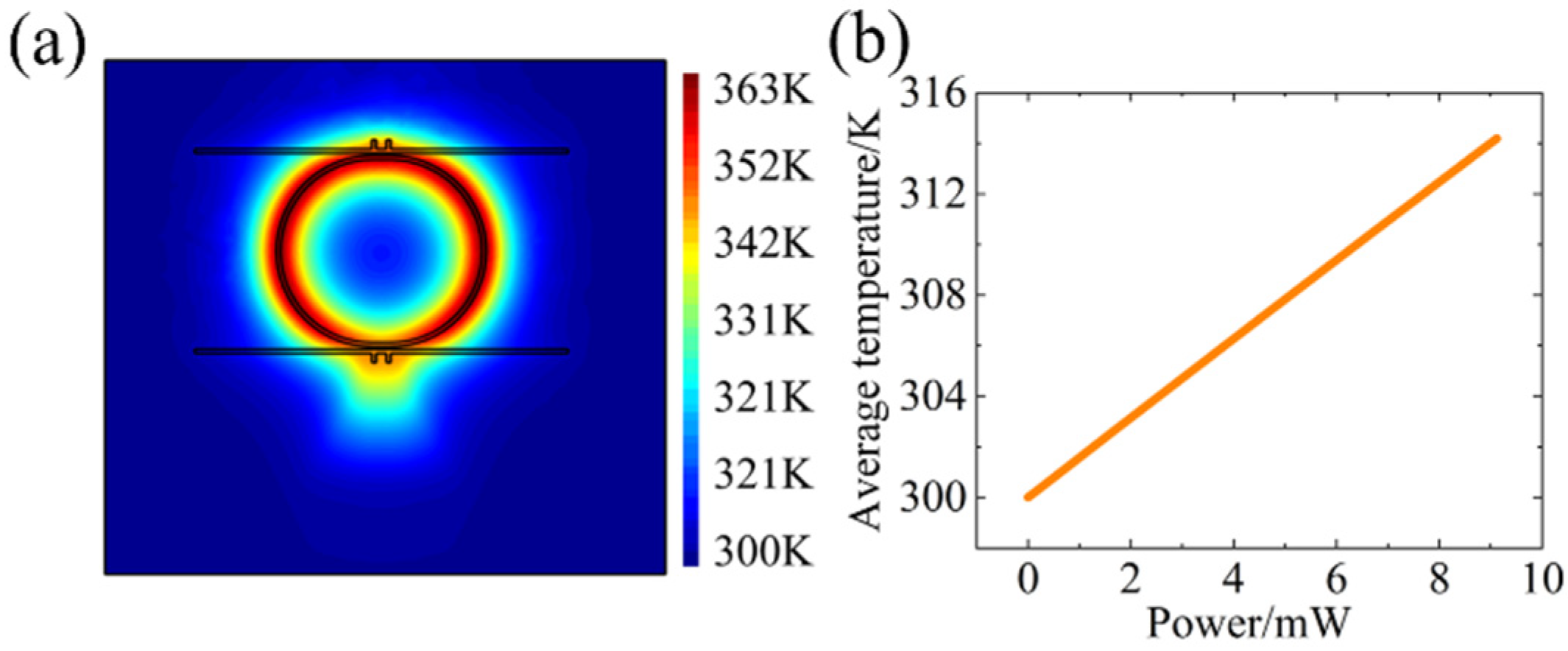
Based on the theoretical analysis above, to obtain the Joule heating effect of the double T-waveguide-coupled micro-ring component, one HEAT module is used to establish a double T-waveguide-coupled raceway micro-ring model to analyze its temperature distribution. The structure of the heating electrode of TiN is shown in
Figure 1. The TiN work function is 4.65 eV, and its thermal conductivity is 19.2 W/(m·K). As shown in
Figure 2a,b, when an electrical power of 9.12 mW is applied to the TiN electrode, the highest temperature inside the component reaches 363 K, with an average temperature of 314 K.
The HEAT module is used to simulate the relation between the voltage and temperature of the device and then imported into the FDTD module. The Fano resonance normalized transmission spectrum of the double T-micro-ring with a wavelength from 1510 nm to 1600 nm with a change in voltages from 0 to 0.7 V is shown in
Figure 3a, which indicates an obvious Fano resonance with the change in driven voltages. As the voltage increases, there are gradual redshifts for the Fano resonance spectrum. The result shows that the wavelength of the double T-waveguide-coupled micro-ring has shifted by 4.45 nm at a voltage of 0.7 V, as shown in
Figure 3b. The electrical field distribution of the optical signal at a resonant wavelength of 1581.38 nm and a non-resonant wavelength of 1587.35 nm for the double T-waveguide-coupled micro-ring are shown in
Figure 3c,d, respectively.
According to the simulation results from the HEAT module in
Figure 2, it can be observed that the square of the driven voltage and the average temperature for the double T-waveguide-coupled micro-ring have a linear relationship, and the relation between the silicon refractive index and temperature is linear. Therefore, the relation between the square of the voltage and wavelength redshift is also linear. Owing to the thermo-optic effect-induced change in silicon refractive index, the temperature variation of the component causes significant wavelength shifts of the resonance peak for the micro-ring.
4. Experimental Demonstration
The double T-waveguide-coupled micro-ring is fabricated based on the above design, and images taken from the optical and scanning electronic microscopes are shown in
Figure 4a,b, respectively. Although some fabrication errors may occur during the process, such as large roughness and comparatively high loss, they can be ignored while only considering the spectrum shift with the change in applied voltage.
To compare the performance between the basic MRR and components with T-waveguide in the experiment, the experimental verification is carried out for MRRs with the help of a semi-automatic coupling platform and probe. As shown in
Figure 5a, a normalized transmission spectrum ranging from 1530 nm to 1600 nm is measured by an optical spectral analyzer (OSA). As shown in
Figure 5b, voltages from 0 to 0.75 V are applied to the TiN electrode, and the normalized transmission spectra are obtained from 1581 nm to 1583 nm, which excludes the spectra of the light source, the optical link, and the grating coupler. As shown in
Figure 5c, the relation between driven voltage and current is measured for the untuned micro-ring, and the total resistance between the two electrodes is calculated from the voltage–current curve, which is about 41.66 Ω. Based on the above spectra and experimental data, the relation between power and wavelength is calculated as illustrated in
Figure 5d, and a similarly linear relation between power and wavelength is obtained.
A semi-automatic temperature-controlled coupling platform where the voltages are applied by the probes to the double T-waveguide-coupled micro-ring is used. Except for adding the double T-waveguide, the structure of the component is the same as that of normal MRRs. As shown in
Figure 6a, the full normalized transmission spectrum ranging from 1530 nm to 1600 nm is measured by OSA. As shown in
Figure 6b, the normalized transmission spectra from 1581 nm to 1585 nm are selected by applying voltages ranging from 0 V to 0.75 V, which excludes the spectra of the light source, the optical link, and the grating coupler.
Compared with the normal MRR, the double T-waveguide-coupled micro-ring has higher wavelength power sensitivity, along with lower power consumption for multiplication operations in convolution. The relation between voltage and current for the double T-waveguide-coupled micro-ring is also obtained in
Figure 6c, which shows that there is a similarly linear relationship between current and applied voltage. This experimental result is consistent with previous numerical simulation results. As shown in
Figure 6c, the total resistance between the two electrodes is calculated, which is about 36.75 Ω. Moreover, it is shown in
Figure 6d that the power–wavelength relation is calculated from the above experimental results and data, revealing a similarly linear relationship between power and wavelength.
5. Discussion
The silicon effective refractive index can be changed by the variation in temperature due to the thermo-optic effect. Even a slight variation in temperature can change the resonant peak of the transmission spectrum for MRRs. For applications in optical computing, it is necessary to obtain the relation between power consumption and light intensity. Therefore, the formula of OIPCS is derived as follows:
where
dΔ
Po,
dΔ
Pe, and
dΔ
λ are optical intensity, power consumption, and wavelength, respectively. Here,
represents the OIPCS, which is obtained by the multiplication of SR and wavelength power consumption sensitivity (WPCS) for Fano resonators. According to Formula (6), the experimental results of the MRR and the double T-waveguide-coupled micro-ring and the SR of the normal MRR and the double T-waveguide-coupled micro-ring are 35.20 dB/nm and 70.30 dB/nm, respectively. The OIPCS of the normal MRR is 2.60 dB/mW, and the WPCS is 0.074 nm/mw. However, the OIPCS of the double T-waveguide-coupled micro-ring is 7.60 dB/mW, and the WPCS is 0.108 nm/mW. Obviously, the SR, OIPCS, and WPCS of the double T-waveguide-coupled micro-ring are significantly improved compared with those of the normal MRR. The reason why there are obvious performance improvements for the double T-waveguides component is mainly that the optical intensity of the Fano resonator changes sharply from 0 to 1 near the resonant peak of the transmission wavelength. For the same change in optical intensity, the power consumption of the double T-waveguide-coupled micro-ring requires only 1/3 as much as that of normal MRRs for the resonant wavelength, which brings higher modulation efficiency and is more suitable for convolution units in optical computing.
6. Conclusions
In this paper, a novel essential component based on a micro-ring resonator for silicon optical computing convolution units is proposed. By adding double T-bus waveguides, a thermal–optical modulator is obtained with a Fano resonance linear transmission spectrum. A large phase shift is obtained by comparatively low driven power around 20 mW in the TiN electrode, where voltage changes generate Joule heat, resulting in a change in the silicon refractive index as well as a wavelength shift for the Fano resonance. Numerical simulation and experimental results demonstrate that the Fano resonance line-shaped transmission spectrum for the double T-waveguide-coupled micro-ring has higher spectral resolution (SR) and optical intensity power consumption sensitivity (OIPCS) than those of the MRR transmission spectrum, which significantly reduces the modulation power required. Besides optical computing, this work also has tremendous potential fields for applications, such as optical switching, optical sensing, and optical communications. In the future, the quality factor of T-shape waveguides can be further improved to enhance the SR, along with superior component performance.

 ,
, 


