Efficient 1054 nm Raman Random Fiber Laser


Abstract
:1. Introduction
2. Simulation and Experimentation of YDFL
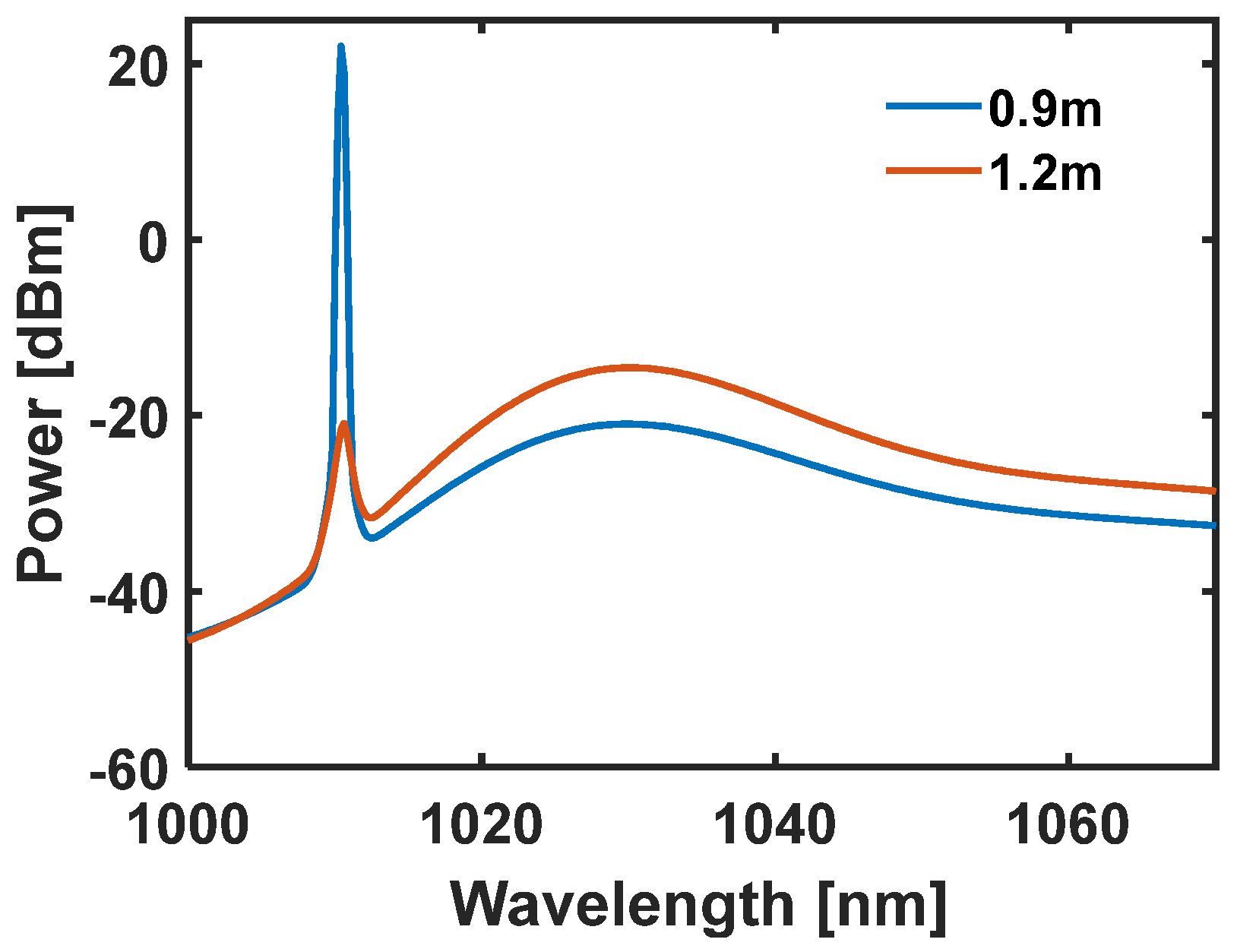
2.1. Simulation of YDFL
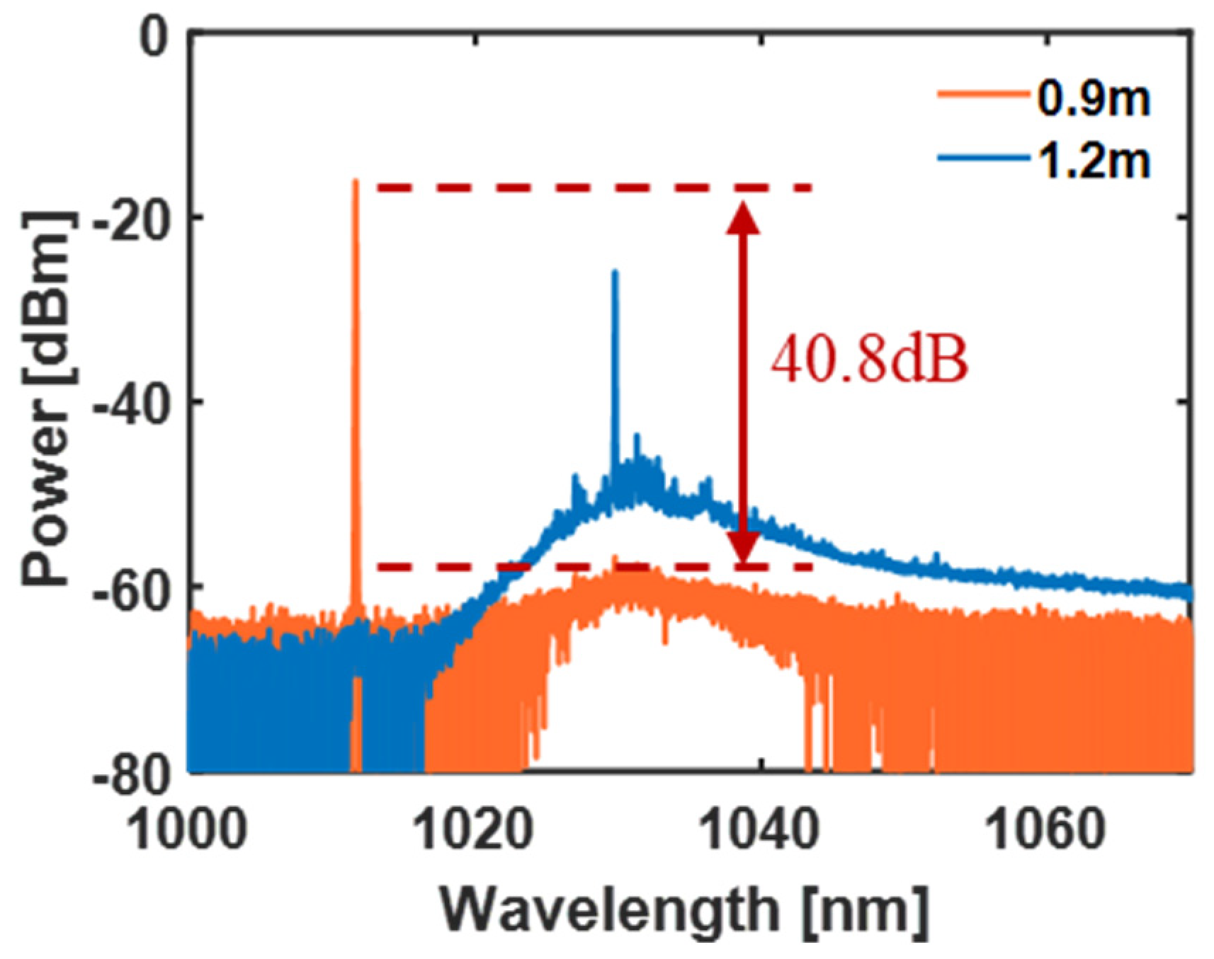
2.2. Experimentation of YDFL
3. Experiments and Results of RRFL
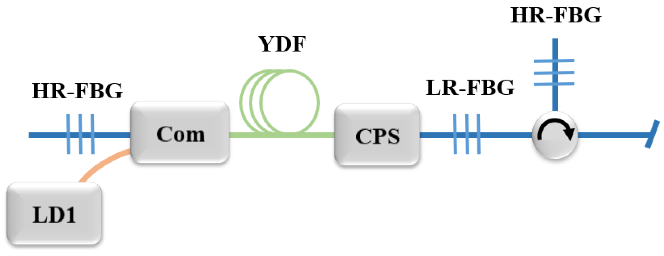
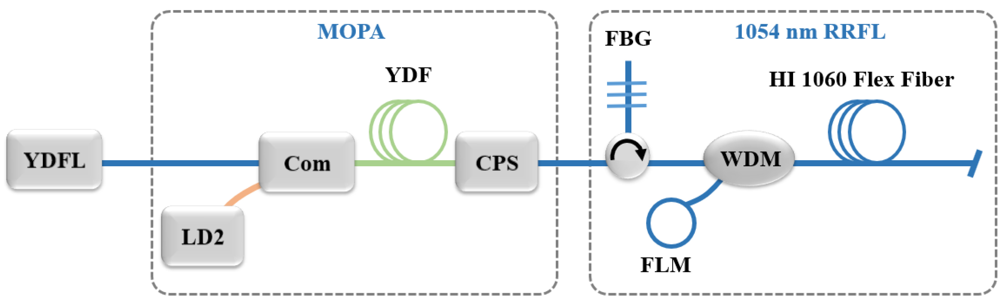
3.1. Experimental Setup
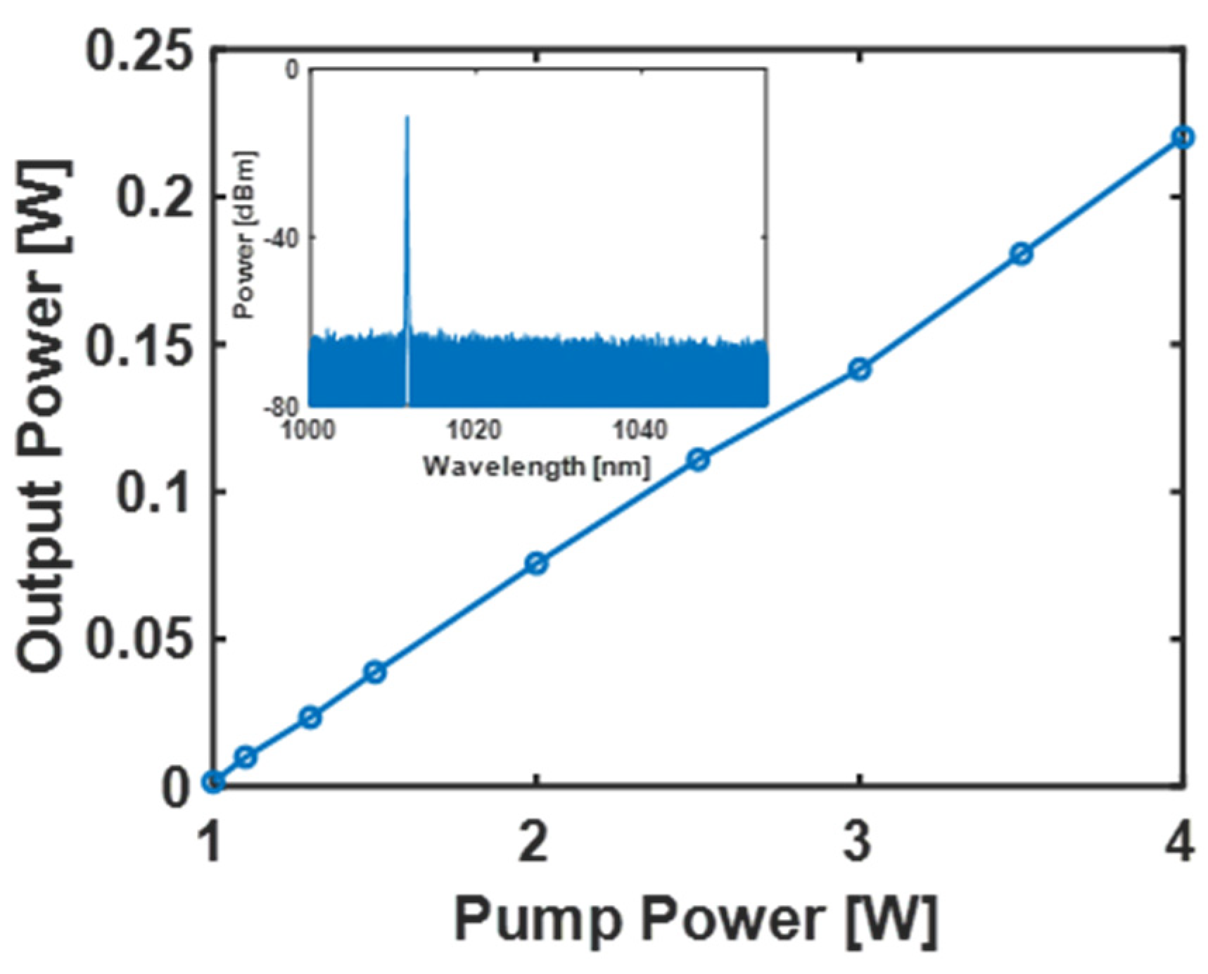
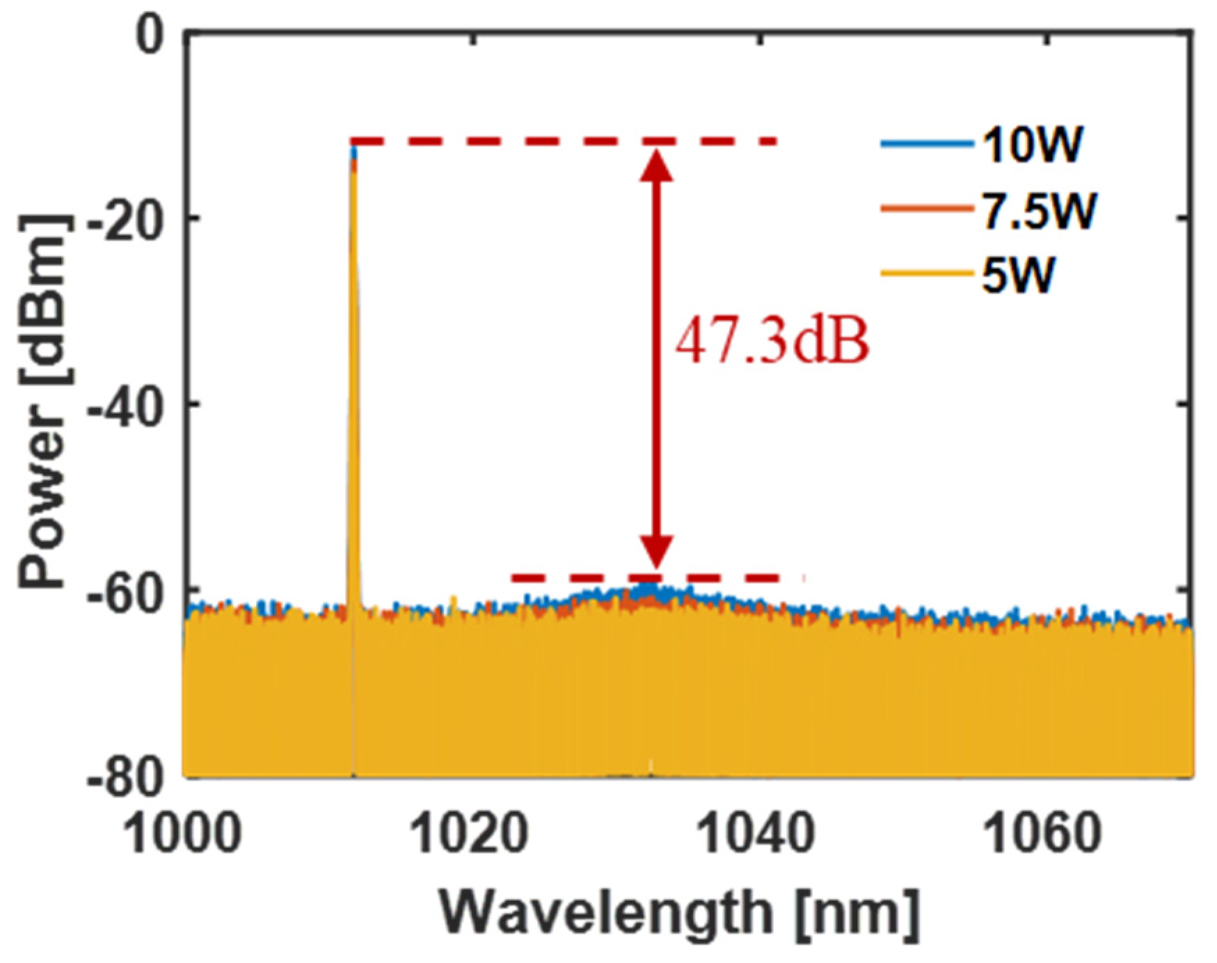
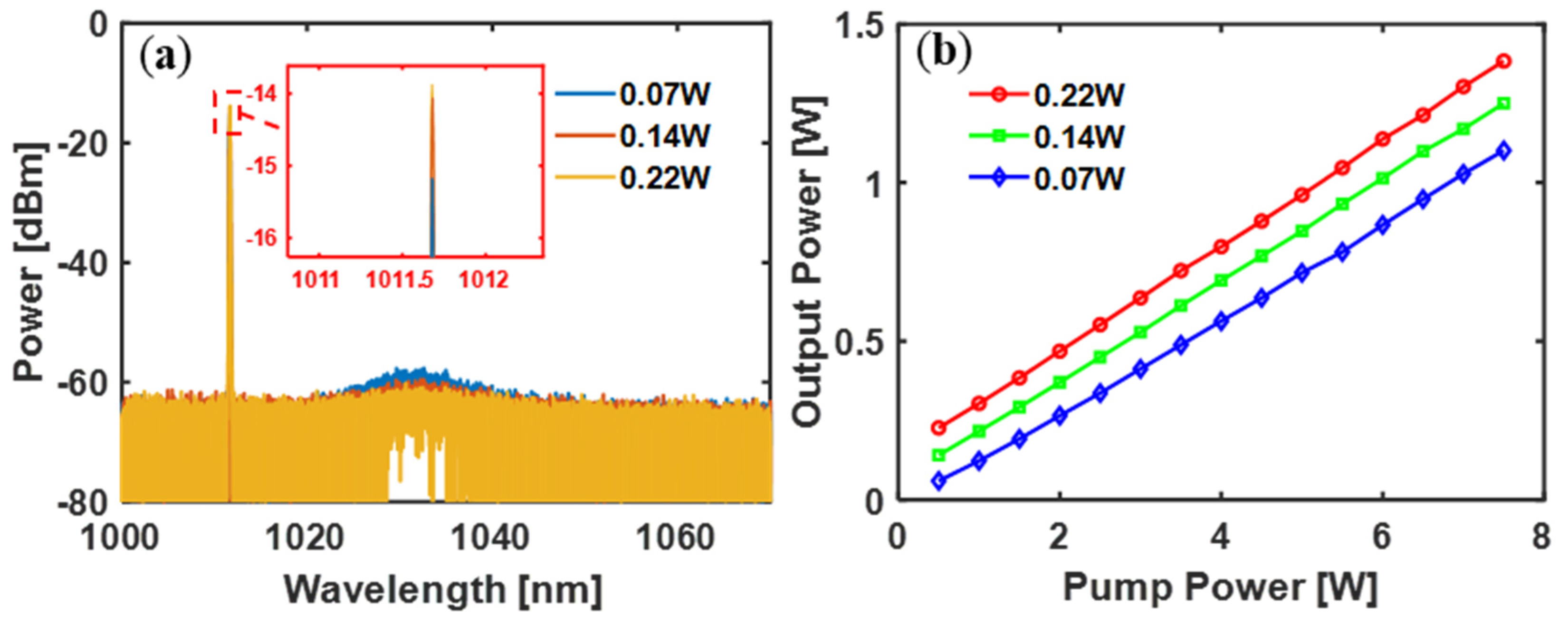
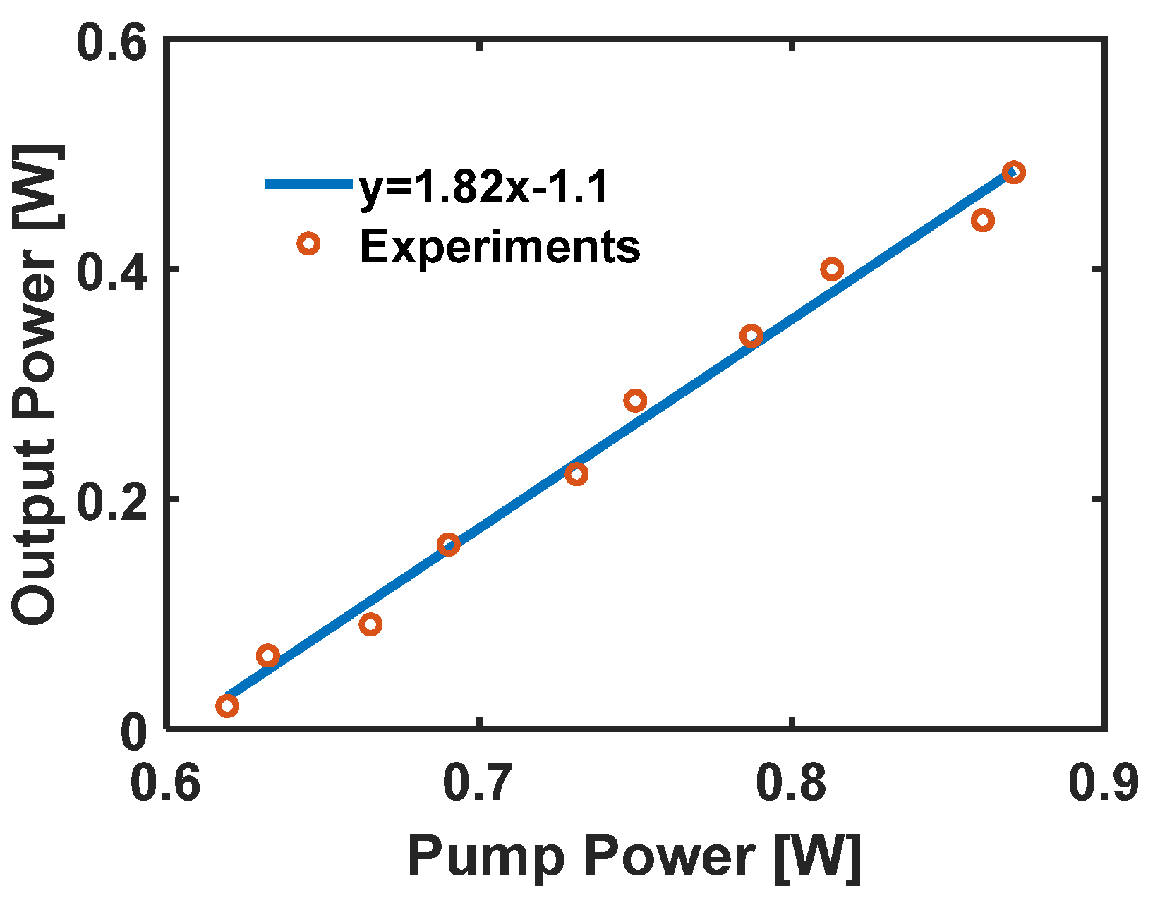
3.2. MOPA
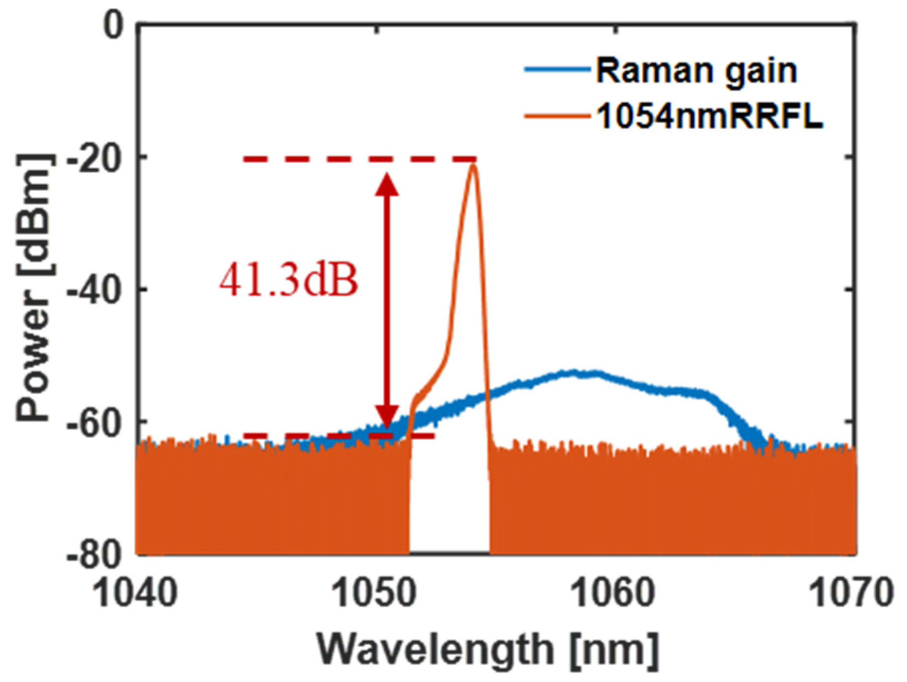
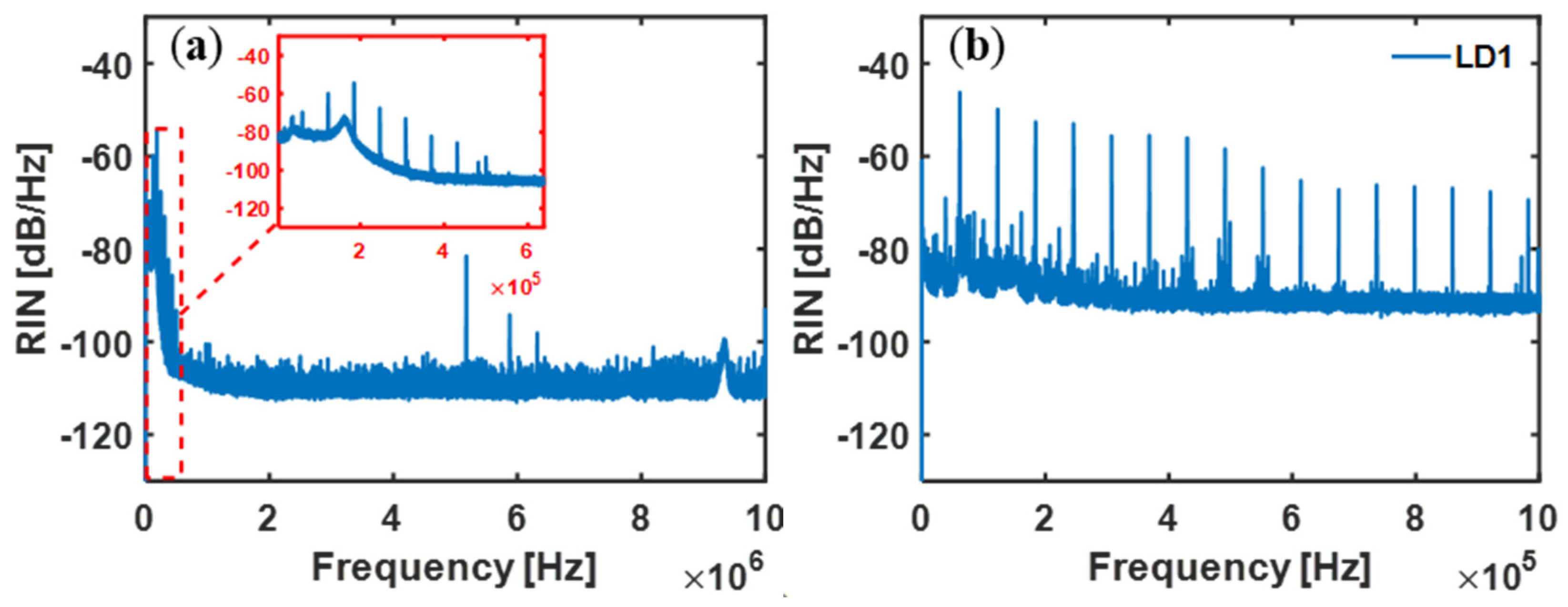
3.3. RRFL
4. Conclusions
Author Contributions
Funding
Institutional Review Board Statement
Informed Consent Statement
Data Availability Statement
Conflicts of Interest
References
- Labaune, C. Incoherent light on the road to ignition. Nat. Phys. 2007, 3, 680–682. [Google Scholar] [CrossRef]
- Lindl, J.; Landen, O.; Edwards, J.; Moses, E.; NIC Team. Review of the National Ignition Campaign 2009–2012. Phys. Plasmas 2014, 21, 020501. [Google Scholar] [CrossRef]
- Obenschain, S.P.; Luhmann, N.C.; Greiling, P.T. Effects of finite–bandwidth driver pumps on the parametric–decay instability. Phys. Rev. Lett. 1976, 36, 1309–1312. [Google Scholar] [CrossRef]
- Mostovych, A.N.; Obenschain, S.P.; Gardner, J.H.; Grun, J.; Kearney, K.J.; Manka, C.K.; McLean, E.A.; Pawley, C.J. Brillouin scattering measurements from plasmas irradiated with spatially and temporally incoherent laser light. Phys. Rev. Lett. 1987, 59, 1193–1196. [Google Scholar] [CrossRef]
- Rao, D.X.; Gao, Y.Q.; Cui, Y.; Ji, L.L.; Zhao, X.H.; Liu, J.; Liu, D.; Li, F.J.; Shan, C.; Shi, H.T.; et al. 1 μJ nanosecond low–coherent laser source with precise temporal shaping and spectral control. Opt. Laser Technol. 2020, 122, 105850. [Google Scholar] [CrossRef]
- Dorrer, C.; Spilatro, M. Spectral and temporal shaping of spectrally incoherent pulses in the infrared and ultraviolet. Opt. Express 2022, 30, 4942–4953. [Google Scholar] [CrossRef] [PubMed]
- Cui, Y.; Gao, Y.Q.; Rao, D.X.; Liu, D.; Li, F.J.; Ji, L.L.; Shi, H.T.; Liu, J.N.; Zhao, X.H.; Feng, W.; et al. High–energy low–temporal–coherence instantaneous broadband pulse system. Opt. Lett. 2019, 44, 2859–2862. [Google Scholar] [CrossRef]
- Dorrer, C.; Hill, E.M.; Zuegel, J.D. High–energy parametric amplification of spectrally incoherent broadband pulses. Opt. Express 2020, 28, 451–471. [Google Scholar] [CrossRef]
- Turitsyn, S.K.; Babin, S.A.; Atalla, E.T.; Harper, P.; Churkin, D.V.; Kablukov, S.I.; Ania–Castañón, J.D.; Karalekas, V.; Podivilov, E.V. Random distributed feedback fibre laser. Nat. Photonics 2010, 4, 231–235. [Google Scholar] [CrossRef]
- Bravo, M.; Fernandez–Vallejo, M.; Lopez–Amo, M. Internal modulation of a random fiber laser. Opt. Lett. 2013, 38, 1542–1544. [Google Scholar] [CrossRef] [Green Version]
- Wu, H.; Han, B.; Wang, Z.N.; Liang, H.K. Statistical properties of Er/Yb co–doped random Rayleigh feedback fiber laser. Chin. Opt. Lett. 2021, 19, 021402. [Google Scholar] [CrossRef]
- Fan, M.Q.; Lin, S.T.; Yao, K.; Qi, Y.F.; Zhang, J.J.; Zheng, J.W.; Wang, P.; Ni, L.Q.; Bao, X.Y.; Zhou, D.D.; et al. Spectrum–tailored random fiber laser towards ICF laser facility. Matter Radiat. Extrem. 2023, 8, 025902. [Google Scholar] [CrossRef]
- Fan, M.Q.; Zon, Z.Y.; Tian, X.C.; Xu, D.P.; Zhou, D.D.; Zhang, R.; Zhu, N.; Xie, L.H.; Li, H.X.; Su, J.Q.; et al. Comprehensive Investigations on 1053 nm Random Distributed Feedback Fiber Laser. IEEE Photonics J. 2017, 9, 1–9. [Google Scholar] [CrossRef]
- Lin, S.T.; Wang, Z.N.; Araújo, H.A.; Raposo, E.P.; Gomes, A.S.L.; Wu, H.; Fan, M.Q.; Rao, Y.J. Ultrafast convergent power–balance model for Raman random fiber laser with half–open cavity. Opt. Express 2020, 28, 22500–22510. [Google Scholar] [CrossRef]
- Han, B.; Dong, S.S.; Liu, Y.; Wang, Z.N. Cascaded Random Raman Fiber Laser with Low RIN and Wide Wavelength Tunability. Photonic Sens. 2022, 12, 220414. [Google Scholar] [CrossRef]
- Lin, S.T.; Wang, Z.N.; Zhang, J.J.; Wang, P.; Wu, H.; Qi, Y.F. Radiation build–up and dissipation in Raman random fiber laser. Sci. China Inf. Sci. 2022. [Google Scholar] [CrossRef]
- Wang, Z.N.; Wu, H.; Fan, M.Q.; Rao, Y.J.; Jia, X.H.; Zhang, W.L. Third–order random lasing via Raman gain and Rayleigh feedback within a half–open cavity. Opt. Express 2013, 21, 20090–20095. [Google Scholar] [CrossRef]
- Zhang, H.W.; Huang, L.; Song, J.X.; Wu, H.; Zhou, P.; Wang, X.L.; Wu, J.; Xu, J.M.; Wang, Z.N.; Xu, X.J.; et al. Quasi–kilowatt random fiber laser. Opt. Lett. 2019, 44, 2613–2616. [Google Scholar] [CrossRef]
- Grimes, A.; Hariharan, A.; Sun, I.; Nicholson, J.W. High–power, high–efficiency, semi–random Raman fiber lasers. Fiber Lasers XIX Technol. Syst. 2022, 11981, 137–141. [Google Scholar]
- Ye, J.; Xu, J.M.; Song, J.X.; Wu, H.S.; Zhang, H.W.; Wu, J.; Zhou, P. Flexible spectral manipulation property of a high power linearly polarized random fiber laser. Sci. Rep. 2018, 8, 2173. [Google Scholar] [CrossRef] [Green Version]
- Wang, Z.N.; Wu, H.; Fan, M.Q.; Zhang, L.; Rao, Y.J.; Zhang, W.L.; Jia, X.H. High power random fiber laser with short cavity length: Theoretical and experimental investigations. IEEE J. Sel. Top. Quantum Electron. 2014, 21, 10–15. [Google Scholar] [CrossRef]
- Dong, J.Y.; Zhang, L.; Zhou, J.Q.; Pan, W.W.; Gu, X.J.; Feng, Y. More than 200 W random Raman fiber laser with ultra–short cavity length based on phosphosilicate fiber. Opt. Lett. 2019, 44, 1801–1804. [Google Scholar] [CrossRef]
- Wang, Z.H.; Yan, P.; Huang, Y.S.; Tian, J.D.; Cai, C.; Li, D.; Yi, Y.Q.; Xiao, Q.R.; Gong, M.L. An Efficient 4–kW Level Random Fiber Laser Based on a Tandem–Pumping Scheme. IEEE Photonics Technol. Lett. 2019, 31, 817–820. [Google Scholar] [CrossRef]
- Wang, Z.H.; Yu, W.L.; Tian, J.D.; Qi, T.C.; Li, D.; Xiao, Q.R.; Yan, P.; Gong, M.L. 5.1 kW Tandem–Pumped Fiber Amplifier Seeded by Random Fiber Laser with High Suppression of Stimulated Raman Scattering. IEEE J. Quantum Electron. 2021, 57, 6800109. [Google Scholar] [CrossRef]
- Du, X.Y.; Zhang, H.W.; Ma, P.F.; Xiao, H.; Wang, X.L.; Zhou, P.; Liu, Z.J. Kilowatt–level fiber amplifier with spectral–broadening–free property, seeded by a random fiber laser. Opt. Lett. 2015, 40, 5311–5314. [Google Scholar] [CrossRef]
- Babin, S.A.; Dontsova, E.I.; Kablukov, S.I. Random fiber laser directly pumped by a high–power laser diode. Opt. Lett. 2013, 38, 3301–3303. [Google Scholar] [CrossRef]
- Du, X.Y.; Zhang, H.W.; Wang, X.L.; Zhou, P. Tunable random distributed feedback fiber laser operating at 1 μm. Appl. Opt. 2015, 54, 908–911. [Google Scholar] [CrossRef]
- Melkumov, M.A.; Bufetov, I.A.; Kravtsov, K.S.; Shubin, A.V.; Dianov, E.M. Lasing parameters of ytterbium–doped fibres doped with P2O5 and Al2O3. Quantum Electron. 2004, 34, 843–848. [Google Scholar] [CrossRef]
- Glick, Y.; Sintov, Y.; Zuitlin, R.; Pearl, S.; Shamir, Y.; Feldman, R.; Horvitz, Z.; Shafir, N. Single–mode 230 W output power 1018 nm fiber laser and ASE competition suppression. J. Opt. Soc. Am. B 2016, 33, 1392–1398. [Google Scholar] [CrossRef]
- Kurkov, A.S. Oscillation spectral range of Yb–doped fiber lasers. Laser Phys. Lett. 2007, 4, 93–102. [Google Scholar] [CrossRef]
- Brilliant, N.A.; Lagonik, K. Thermal effects in a dual–clad ytterbium fiber laser. Opt. Lett. 2001, 26, 1669–1671. [Google Scholar] [CrossRef]
- Wang, J.H.; Chen, G.; Zhang, L.; Hu, J.M.; Li, J.Y.; He, B.; Chen, J.B.; Gu, X.J.; Zhou, J.; Feng, Y. High–efficiency fiber laser at 1018 nm using Yb–doped phosphosilicate fiber. Appl. Opt. 2012, 51, 7130–7133. [Google Scholar] [CrossRef] [PubMed] [Green Version]
- Xiao, H.; Zhou, P.; Wang, X.L.; Guo, S.F.; Xu, X.J. Experimental Investigation on 1018–nm High–Power Ytterbium–Doped Fiber Amplifier. IEEE Photonics Technol. Lett. 2012, 24, 1088–1090. [Google Scholar] [CrossRef]
- Richardson, D.J.; Nilsson, J.; Clarkson, W.A. High power fiber lasers: Current status and future perspectives. J. Opt. Soc. Am. B 2010, 27, 63–92. [Google Scholar] [CrossRef]
- Jauregui, C.; Limpert, J.; Tünnermann, A. High–power fibre lasers. Nat. Photonics 2013, 7, 861–867. [Google Scholar] [CrossRef]
- Huang, Y.S.; Yan, P.; Wang, Z.H.; Tian, J.D.; Li, D.; Xiao, Q.R.; Gong, M.L. 2.19 kW narrow linewidth FBG–based MOPA configuration fiber laser. Opt. Express 2019, 27, 3136–3145. [Google Scholar] [CrossRef]
- Jacquemet, M.; Mugnier, A.; Corre, G.L.; Goyat, E.; Pureur, D. CW PM multiwatts Yb–doped fiber laser directly emitting at long wavelength. IEEE J. Sel. Top. Quantum Electron. 2009, 15, 120–128. [Google Scholar] [CrossRef]


| Parameters | Pump | Emission |
|---|---|---|
| (nm) | 976 | 1011 |
| (m2) | 2.476 × 10⁻²⁴ | 8.634 × 10⁻²⁶ |
| (m2) | 2.483 × 10⁻²⁴ | 4.488 × 10⁻²⁵ |
| (m−1) | 0.006 | 0.005 |
| 0.0064 | 0.9 | |
| 6.626 × 10⁻³⁴ | ||
| (m2) | 7.854 × 10⁻¹¹ | |
| (ms) | 0.8 | |
Disclaimer/Publisher’s Note: The statements, opinions and data contained in all publications are solely those of the individual author(s) and contributor(s) and not of MDPI and/or the editor(s). MDPI and/or the editor(s) disclaim responsibility for any injury to people or property resulting from any ideas, methods, instructions or products referred to in the content. |
© 2023 by the authors. Licensee MDPI, Basel, Switzerland. This article is an open access article distributed under the terms and conditions of the Creative Commons Attribution (CC BY) license (https://creativecommons.org/licenses/by/4.0/).
Share and Cite
Wang, P.; Lin, S.; Zhang, J.; Bao, X.; Ni, L.; Qi, Y.; Wang, Z. Efficient 1054 nm Raman Random Fiber Laser. Photonics 2023, 10, 851. https://doi.org/10.3390/photonics10070851
Wang P, Lin S, Zhang J, Bao X, Ni L, Qi Y, Wang Z. Efficient 1054 nm Raman Random Fiber Laser. Photonics. 2023; 10(7):851. https://doi.org/10.3390/photonics10070851
Chicago/Turabian StyleWang, Pan, Shengtao Lin, Jiaojiao Zhang, Xingyu Bao, Longqun Ni, Yifei Qi, and Zinan Wang. 2023. "Efficient 1054 nm Raman Random Fiber Laser" Photonics 10, no. 7: 851. https://doi.org/10.3390/photonics10070851