1. Introduction
Radiation of the THz range possesses unique properties for fundamental material studies and high-end applications in medicine, chemistry, and communication [
1,
2,
3,
4]. The non-ionizing nature of the interaction makes possible non-destructive ultra-sensitive contamination [
5] and chemical compound detection by terahertz spectroscopy [
6,
7]. In biology, with this kind of radiation, the spectroscopy of biomolecules [
8], chemical imaging [
9], and even the monitoring of bio-samples’ content [
10] become feasible. THz time domain spectroscopy [
11,
12] is used for protein and RNA dynamic polarization-dependence response [
13] and DNA studies [
14]. Terahertz technology is developing in intraoperative neurodiagnostics [
15] and may be used for tissue detection [
16]. The high potential of medical THz applications is defined by its safety at high intensities, which helps to obtain high image contrasts [
17]. This radiation range is extremely interesting in the frames of fast material properties’ modification [
18] and terahertz wireless communication systems [
19].
Among the different possible applications of THz radiation, many require certain controlled polarization properties, such as, e.g., molecular orientation and alignment [
20,
21,
22], the detection of inclusions in matter [
23], reflective time domain polarization spectroscopy [
24], etc. Furthermore, some studies require a certain THz field strength, such as, e.g., the THz pump-probe technique for characterizing materials and studies aiming at understanding traditional nonlinear effects [
25] at the high and ultra-high interaction level. There is a need for a good polarization control for strong-field terahertz time domain polarimetry and ellipsometry and nonlinear terahertz spectroscopy beyond the MV/cm electric field strength [
3]. Along with the development of intense THz sources, intense THz magnetic fields have also been explored. The intense THz magnetic field can strongly couple to a spin subsystem and be used to coherently control the precession of macroscopic magnetization [
25]. The intense THz radiation of different polarizations may be used for ionic motion control, lattice vibrations, coherent control of molecular orientation and rotation, spin manipulation in different materials, ionization at low frequencies, and induced phase transitions [
26]. Many studies are devoted to particle acceleration with strong polarized THz radiation [
27,
28,
29,
30].
The polarization control of strong THz radiation may be obtained with further development of general schemes for THz generation, such as optical rectification in nonlinear crystals [
31] and photoconductive emitters [
32]. Higher intensities of polarized THz radiation are achievable using liquids [
33] or gases under strong optical pumping. Some schemes involve additionally static external fields, such as strong magnetic fields of a few hundred Tesla [
34] or electric fields of a special geometry [
35]. Some other propositions deal with different combinations of pumping laser beams with different intensities, wavelengths, or polarizations [
36,
37]. However, these are usually schemes driven with TW-class fs lasers and with ∼
efficiency, which limits the expected THz power to the GW scale. The reachable power of polarized THz sources remains one of the most-important questions in the field. Its increase may allow stronger induced effects and lead to the development of new methods and applications.
Probably, plasma sources driven by high-intensity laser pulses are the best candidates for obtaining unprecedentedly strong THz radiation on the terawatt scale. Among the variety of plasma-based schemes, some of the most-interesting ones are emitters fed by strong laser-induced localized electric currents. They offer a promising potential as a source of powerful THz radiation and have been thoroughly investigated both numerically and experimentally for straight laser-driven metallic wires [
38,
39,
40,
41,
42]. Note that, there, mainly the collective motion of fast laser-accelerated electrons was considered to be responsible for the THz emission, but the induced surface currents may provide a more-compact and dense radiation source [
43]. One of the effective mechanisms for creating such currents involves driving an intense discharge pulse [
44,
45,
46]. For smaller, e.g., sub-picosecond or even femtosecond laser pulses, the degree of localization of this discharge pulse may become sufficiently small on the target scale, and it may emit electromagnetic waves when propagating along a coil-shaped [
45] or an undulating [
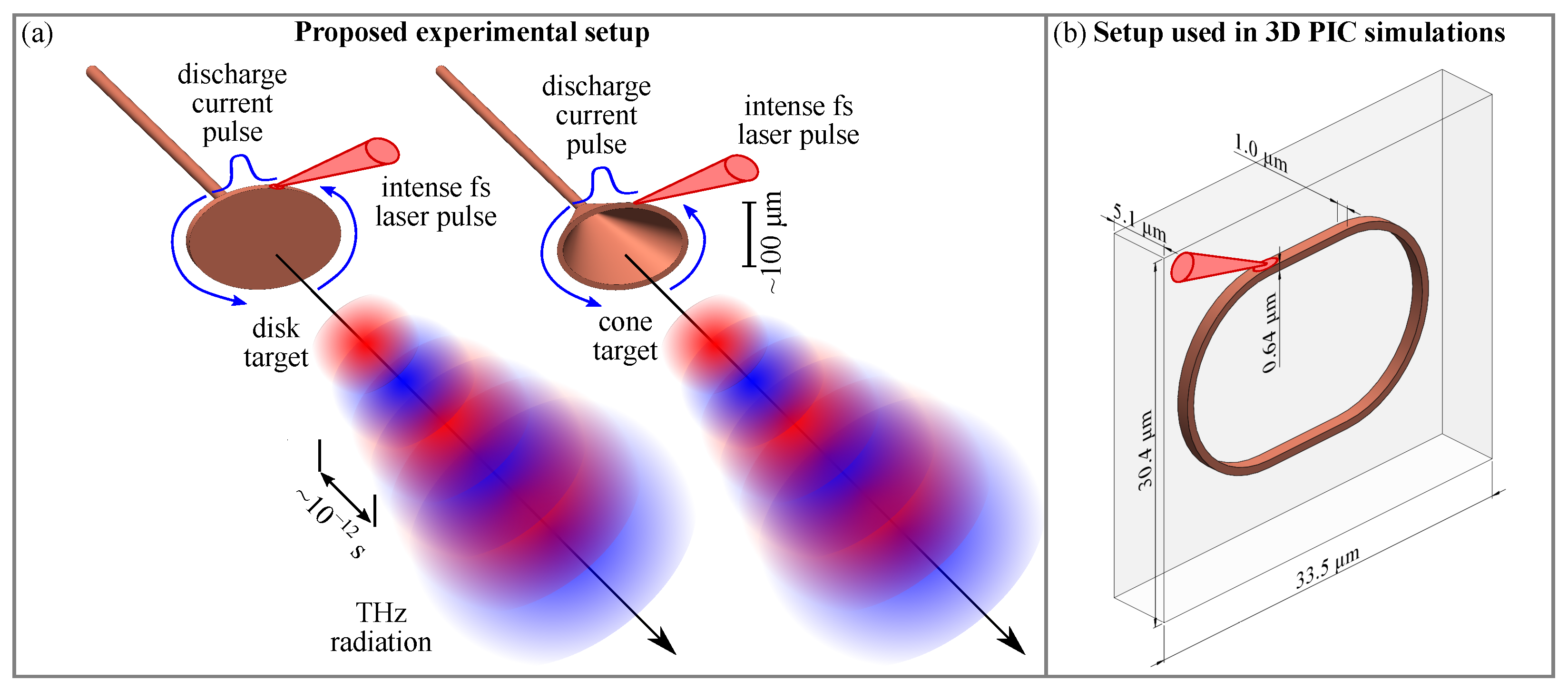
43] wire. Here, we show that a simple solid target with an elliptical outer surface allows obtaining perfectly controlled polarized THz radiation along the normal to the target with the frequency defined by the target perimeter and the degree of ellipticity defined by the ratio of the minor and major axes of the target ellipse. Such a target may present either a disk with a mount connected to its center or a truncated cone with elliptical bases and the mount connected to the smaller base; see
Figure 1a. In both cases, a short and fast current driven by an intense femtosecond laser pulse would propagate on the target’s outermost surface because of the skin effect, i.e., along the disk outer surface or the cone larger base. Thus, for the considered effect, only the shape and size of the outer border should play a role, while other parts of the target may have arbitrary profiles as long as they do not carry any significant electric current. As we show below, for an interaction at small angles, the current propagation direction is defined by the irradiation direction, so that it is counterclockwise for the irradiation geometry in a possible experimental setup presented in
Figure 1a and clockwise for the 3D simulation geometry in
Figure 1b. As the target’s outer surface presents a closed loop, no specific conditions are required to close the circuit, which enables the current pulse to make several round turns, as in the case of the coil with a plasma-connected slit [
45]. The setup enables the production of multi-period strong waves with perfectly controlled polarization and spectra, which may provide unique possibilities in studies requiring ultra-strong polarized THz radiation. In the workflow of the previous experimental [
39,
40,
41,
42] and theoretical [
35,
37,
38,
43,
45] studies aiming at the generation of strong controlled radiation in the THz domain, the work presents a design-theoretical description of the the powerful THz emitter with the possibility of enhanced polarization control, promoting further experimental research of THz sources driven by compact optically induced discharges.
3. Results
The results of the performed 3D PIC modeling for the target profile shown in
Figure 1b indicates that an ultra-short intense laser pulse hitting the upper straight segment of the target at a small angle, as shown in
Figure 2a, creates a strong and short discharge current pulse; see
Figure 2b. It propagates around the target clockwise (see
Figure 2d–g) due to the chosen irradiation geometry, which defines the direction of the laser-driven discharge current pulse. During the simulated time, the discharge current pulse went a full round trip around the target with almost no observable dispersion and started another round; see
Figure 2h,i. As no stretching of the pulse over the target perimeter occurred and it stayed well-localized on the coil scale, it preserved its capability of emitting electromagnetic waves. Although, it should be noted that its amplitude may decrease due to ionization [
43] and collisionless damping [
46], leading to slow variations of the envelope of the emitted radiation. Its main frequency is defined by the inverse time of a single round trip of the discharge current pulse, which depends on the target size and geometry, as well as on the propagation velocity of the discharge current pulse. The latter, according to the performed modeling, amounted to about
c, as the current pulse traveled 66
m along the target perimeter in about 250 fs. The obtained propagation velocity was somewhat lower than the value reported in [
43] for a straight wire target, but it should be noted that, here, due to the loop-like target geometry, the discharge current pulse propagated in the plasma formed by the weaker counter-clockwise discharge pulse, propagating in the opposite direction from the interaction region, in contrast to the case of a cold extended wire, where the plasma in front of the discharge current pulse was not excited. As was shown in [
46], this near-surface plasma may modify the process of discharge current pulse propagation and lead to a decrease of the propagation velocity. The simulations over the times
ps in the considered 3D geometry for the dense plasma and small cell sizes were rather expensive and were not performed, as the results shown in
Figure 2h,i and the results of other studies with similar setups [
45] showed that the discharge pulse was able to make at least a few oscillations around the target before its amplitude reduced to some background level or before it stretched over the whole target perimeter.
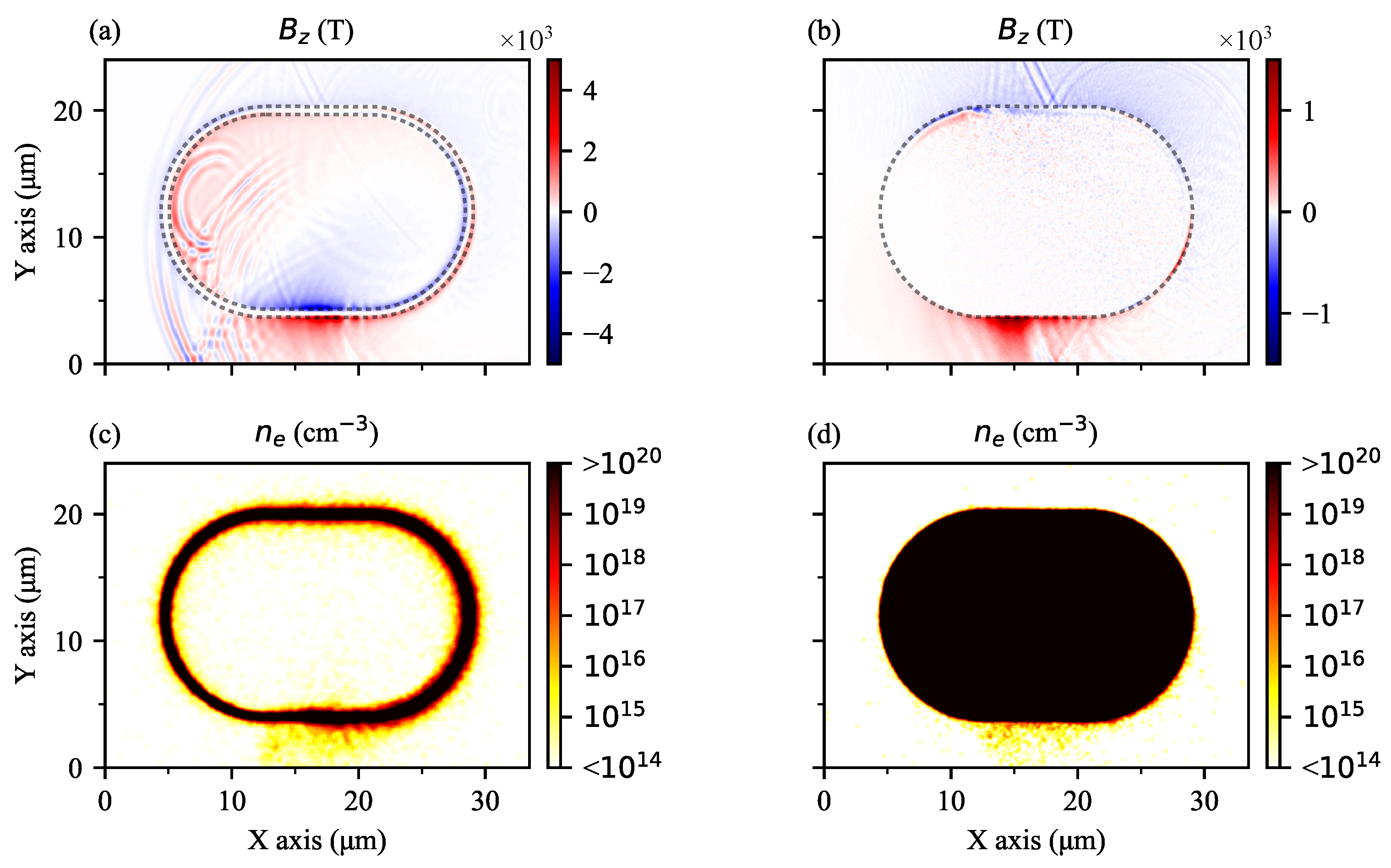
For the two possible experimental realizations of the setup, shown in
Figure 1a, it should be noted that, although the current propagated in the thin outermost layer of the target due to the skin effect, the presence of the inner conducting medium may affect qualitatively the process of the surface discharge current pulse formation and propagation. In order to demonstrate these changes, an additional 3D PIC simulation was performed with the same conditions as before, but for a target with the inner volume that was filled with plasma with the same density as for the external current-carrying layer. Due to the constraints imposed by the increased computational load required to model such a target, the simulation time was limited to half of the first oscillation period. The comparison of the resulting discharge current pulse profiles in the form of the
component at time moment ≈0.19 ps is shown in
Figure 3a,b for the “hollow” and “filled” “stadium” targets, respectively; the corresponding electron density profiles are presented in Panels (c) and (d). From the presented plots (see Panels (a) and (b)), it can be seen that there were some differences in the process of discharge current pulse propagation along the coil, namely the profiles were slightly different, the amplitude appeared to be ≈2.5-times less than for a hollow target, and the propagation velocity was a few percent higher. However, qualitatively, the process did not change, supporting the main conclusions of the work, that an intense compact discharge current pulse was formed and propagated along the target’s outer surface with no observable dispersion. This occurred regardless of the target’s inner medium, and thus, both the disk and the cone target shown in
Figure 1a enabled the charge oscillation along the given trajectory in a similar way.
Further analysis was based on the results of the main simulation, i.e., that with the profile presented in
Figure 1b. The examination of the spatial distributions of other physical quantities besides the axial component of the magnetic field may provide more insight into the interaction processes. The electric fields
and
, electron density
, and electric current densities
and
are presented in
Figure 4, for two different time moments
fs (Panel (a)), when the discharge current pulse propagated along the right semicircle, and
fs (Panel (b)), when it propagated along the lower straight segment. From the presented distributions, it follows that the electric field also had a mono-polar distribution, similar to that of the magnetic field; see
Figure 4(b1,c2). This was directed normally from the wire, confined fast electrons that escaped the target, and guided them along the surface of the wire; see
Figure 4(d1,d2). Because of that, another current component besides the return discharge current appeared. This can be seen in
Figure 4(f1,e2), where the two current pulses of opposite polarities can be identified. The one
corresponded to the return flow of the bulk electrons and is shown with the blue arrow in Panel (f1). This flow was directed counter-clockwise, while the discharge current itself was directed clockwise. The other current,
, was created by the flow of electrons accelerated along the surface of the wire. It had the opposite direction to the return flow of the cold bulk electrons and is marked by the red arrow in Panel (f1). Here, the return flow dominated, which is the usual situation [
50], and the polarity of the magnetic field created around the target was defined by the direction of this discharge current.
With the method, described above, the vector potential (
9) may be represented using exponential forms of trigonometric functions
where
and
is a polarization vector. Therefore, as probably could be expected, the electromagnetic field harmonics, radiated by a left-oriented current pulse propagating along an elliptic circuit in the direction normal to the ellipse, are left-handed elliptic polarization with the components ratio coinciding with the ratio of the ellipse semi-axes. As limiting cases, expressions for circular target
or linear target
or
may be obtained from the general expression (
11).
The electric and magnetic fields in a general elliptic case along an arbitrary direction
read
Along the axis normal to the target plane (
,
), these expressions may be simplified as
with
, and in the target plane (
), the far fields transform to
where
it the azimuthal unit vector. In the later case, the electromagnetic wave is linearly polarized, the electric component is in the plane, and the magnetic one is normal to it.
A Fourier component of the electric field reads
where
is the oscillation period,
is the main radiation frequency,
is the full elliptic integral of the second kind, and
It follows from (
15) that, on the target axis, where
, only odd elliptically polarized harmonics are present. The absence of even harmonics is a general feature of the radiation related to the target symmetry [
51,
52].
Using the general expression, the effect of the finite pulse shape may be analyzed with the following generalization to the current (
8):
which introduces a current pulse profile
. As we see, the polarization properties do not change for a finite pulse width. To model a damping of the discharge pulse during its propagation along the wire, a characteristic function
may be introduced, so that the current becomes:
Evidently, the polarization properties would not also change in this case, as the damping results just in multiplication by a time-dependent function.
4. Discussion
Spectral and polarization control of the radiation were provided by the target geometry as described above. In addition to the general analytical consideration, a detailed model analysis of these properties may be performed numerically, using the vector potential (
9) for a given discharge current profile and the target geometry. Then, electromagnetic fields can be calculated as a function of time and their spectral and polarization characteristics can be studied. As an example, here, we presented the obtained results for three elliptical targets with the same perimeter, corresponding to an oscillation period of 1 ps, and different ratios of the major and minor semi-axes:
,
, and
. This relatively large target was considered here for a more-realistic situation, which means also a longer laser beam, so the parameters of the interaction and those of the discharge current pulse were taken from [
43]. The fields were calculated on the axis of the target in the wave zone, at a distance 10 cm from the center of the target, which was much larger than its characteristic size ∼100
m. The obtained results are summarized in
Figure 5. For an almost circular target, with
, the power spectral density (PSD) distribution included a single pronounced peak, almost as it was for a rotating charge [
51]; see
Figure 5a1. The central frequency of this peak was
THz, which corresponded to the inverse time of one oscillation period and was consistent with previous results for the spectrum of the THz radiation produced by the short discharge current oscillating in annular targets [
45]. The width of this peak is mainly defined by the finite duration of the THz emission resulting from the dissipation of the discharge pulse energy. To demonstrate the dependence of the spectral properties on the current pulse energy dissipation rate, consider a strong dissipation, so that the number of oscillation cycles the discharge current pulse makes before its amplitude reduced by
e times was just
. In this case, the spectral peaks widened significantly in comparison to the case of
, and an additional enhancement attributed to the slow change of the emitted field intensity appeared at
THz. For larger
ratios, when the target substantially differed from a circle, the PSD distributions changed, so that additional frequency components appeared at the odd harmonics of the main frequency; see
Figure 5(a2,a3). This effect was more pronounced for
, where the power emitted at the third harmonic amounted to about 25% of the power emitted at the main frequency; in addition, in this case, higher odd harmonics, i.e., the fifth one, became quite noticeable. If the electric fields at each of these harmonics were selected and filtered from the spectrum, it can be seen that the electric field vector drew an ellipse in time.
In addition to the ellipticity, the change of
also led to an increase of the higher harmonics. Each harmonics of the emitted radiation had a certain elliptical polarization defined by the target, though the total electric field drew a complicated line; see
Figure 5(c1–c3). There, dashed lines correspond to the case when there is no discharge dissipation, and the solid ones show the polarization curve in time for
. For
, the observed deviation from an ellipse was not that evident, but with the increase of
, when higher harmonics start to provide a significant contribution to the total emitted field, this effect became noticeable. The inclusion of the dissipation into the calculations led to the gradual decrease of the field amplitude with no changes in the overall polarization, which remained the same during the whole process of the THz wave emission. As was already noted above, the polarization of each harmonic was elliptical, but it was also slowly affected by dissipation; see
Figure 5(b1–b3). There, the dashed line for the main frequency presented the energy conservation limit, while the real polarizations of the radiation at odd frequencies, emitted by a dissipating current pulse, were elliptic spirals, shown in
Figure 5(b1–b3) for a relatively strong dissipation rate with
. The phase difference between the harmonics resulted in a complex non-elliptical polarization, shown in
Figure 5(c1–c3). Filtering frequencies and retaining only the necessary one may be applied to obtain almost elliptically polarized THz radiation in the wave zone on the target axis. Note that, for different angles to the target axis, the polarization of each harmonic changed its ellipticity from linear (in the plane of the target) to a more-general one with the parameters of ellipticity defined by the target and the angle. This spatial polarization sweeping may in principle be converted to the temporal one for use with a single sample. This is just one example of how this setup may provide the unique possibility to reveal the properties of matter and study the material modification and solid-state excitation under strong controlled radiation in a given temporal and spatial domain.
Another merit of the considered scheme is that the spectral and polarization control is coupled with the capability of obtaining extremely intense terahertz radiation when using modern laser systems. Estimate the expected THz radiation power in this case. Consider as a simple example the elliptical target with the relation of the major and minor axes close to unity. The emitted power density per unit solid angle
can be calculated using the expression for an annular coil target on the axis [
45]:
where
a is the radius of the coil and
k is the wave vector. Assuming the main frequency is defined by the perimeter of the coil (
), a monochromatic spectrum and the effective emission solid angle of
sr, the total emitted power:
and depends only on the amplitude of the electric current in the coil. In the reduced numerical simulations performed here with a total laser energy of ≈130 mJ, the total electric current amplitude was about
A. Converting to the Gaussian units and using (
19), one obtains
GW of emitted power in the THz range. For a realistic laser and target parameters, the energy invested into the discharge current pulse excitation may be several orders of magnitude greater, which increases the estimate, respectively. The analysis performed in [
43] showed that, for intensities in the range
–
W/cm
, achievable with modern petawatt and multi-petawatt laser facilities and realistic focusing parameters, electric currents up to
–
A may be obtained. This corresponds to the peak power of the 10 GW-1 TW level, suitable for a wide range of studies of intense and ultra-intense terahertz radiation interaction with matter.
A more careful estimate of the emitted power should take into account its angular distribution, as well as a more-realistic target geometry and the profile of the discharge current pulse. This can be achieved by the numerical calculation of the retarded vector potential given by (
9) and the corresponding electromagnetic fields
and
. These fields may be used to find the Poynting vector
and its integration over time to find the energy fluence. Such calculations were performed for elliptical targets with different ratios of the major and minor semi-axes
a and
b and the same perimeter corresponding to the oscillation period
ps. The used discharge current velocity
was obtained in the PIC simulations; the discharge current profile was taken from [
43]. In addition, two separate calculations of the energy fluence were performed for the “stadium” target considered in the PIC simulations and the elliptical target with the same
and the same perimeter as for the “stadium” target. The results are presented in
Figure 6.
For a circular target with
, most of the power was radiated in the plane of the target, i.e., the
plane (see
Figure 6a), resulting in bright and relatively wide maxima in the
mm and
mm planes in the presented fluence distribution. The difference between this distribution and that for the circular target with a maximum along the target axis presented in [
45] came from the wider discharge current profile. Indeed, a rotating point relativistic charge emitted mostly in the rotation plane, and the spectrum had higher frequencies, the higher the charge velocity was [
51]. For a finite charge profile, the higher frequencies were suppressed, and for the profile with a characteristic width of the order of the target perimeter, only the main harmonic in the radiation spectrum with a maximum along the target axis survived [
45]; see also the results for the small target and the same charge profile width, shown in
Figure 6e,f.
As the relation
increased, the radiation patterns changed substantially; see
Figure 6b–d. The intensity of the radiation along the target axis grew and became comparable in magnitude to the intensity in the plane of the target. At the same time, due to the introduced asymmetry of the target sides, patterns in the
mm and
mm planes began to differ from one another. The one in
mm mostly retained its uniform shape, while for the pattern in
mm, a noticeable drop in the intensity appeared in the direction of the
x axis, i.e., along the longer side of the target. At
, the distribution in
mm plane attained a doughnut-like shape with a hole in the center; see
Figure 6d. This result was consistent with the angular distributions of the power emitted by a compact current oscillating in a straight wire; see the Supplementary Material in [
43] for details. For a smaller “stadium” target with the sizes from the simulation above and the discharge current with the same parameters as those for the larger elliptical targets, the distribution had a more pronounced maximum along the axis of the target, in the
mm plane, rather than in the
mm and
mm planes; see
Figure 6e. For a comparison, an elliptical target with the same perimeter, corresponding to the oscillation period of
ps and with the same
relation, was considered. The calculations yielded similar results as for the “stadium” target (see
Figure 6f), confirming that the degree of localization of the discharge current on the coil perimeter played an important role and defined the angular distribution of the emitted power.
Integrating fluence distributions over the boundaries of the simulation box allowed the estimation of the total emitted energy and the average emitted power. For the electric current of
A driven in the small “stadium” target, as in the PIC simulations presented here, the total emitted energy was ≈7
J per one period and the average emitted power was ≈2.8 GW, somewhat larger than predicted by a simplified treatment using (
19), probably resulting from a larger effective solid angle of the emission than the initially anticipated 1 sr. The resulting conversion efficiency with the invested laser energy of 130 mJ appeared to be about
% per period. For the electric current of
A, which can be driven [
43] by a laser pulse with intensity
W/cm
, the emitted energy per period may reach
J and the average emitted power per period increased to ≈0.3 TW. For larger elliptical targets and the same electric current of
A, the integration of the fluence distributions (
Figure 6a–d), per all emission directions, yielded somewhat larger total emitted energies of ≈0.1 J per period, though due to the greater period, the average emitted power was less than for smaller targets and amounted to ≈0.1 TW for all the considered
ratios. The estimated laser energy required to drive the electric current of
A was about 25 J, assuming a tight focusing of a 25 fs-long laser pulse to obtain the intensity of ∼
W/cm
. The conversion efficiency then also amounted to about
%, similar to the estimate provided for the “stadium” target and the laser energy used in the simulations. If the discharge pulse was capable of traveling several target periods without a significant decrease of its amplitude, the efficiency of
% per period would result in the total conversion efficiency of about a few percent, which was comparable or surpassed the efficiency of other setups for the generation of intense THz radiation [
53].
An important question that defines the possible range of applications and the efficiency of the proposed scheme is the decay rate of the discharge current pulse during its propagation along the wire surface. According to the results of the performed numerical simulations, for the thin wire considered here, the decay rate appeared to be considerable, similar to that reported for a 1
m-thick wire in [
43]. However, for thicker wires, much lower decay rates have been observed experimentally; see [
46], where no dissipation was noticed on the scale of a few millimeters, and [
54], where the electron motion guided by the laser-induced fields traveling along the wire was observed over distances of up to 1 m. These experimental results suggest that, under appropriate conditions, the damping of the discharge wave can be lowered and become negligible on the spatial scale of an oscillation period ∼
–
m. In this situation, it should be possible for the discharge pulse to make several full turns, emitting multi-period polarized THz waves. Although, a careful treatment of discharge propagation along a wire with realistic sizes is rather complicated and requires further research.
Another point that has to be addressed in the context of the further realization of the proposed scheme is the relation between the reduced simulated geometry and that experimentally accessible. In a more-feasible setup, laser pulses are expected to have a duration of a few tens of femtoseconds rather than of the 4 fs considered here, with the focal spot on the target surface being about a few microns. The process of the discharge current pulse formation under the laser irradiation of a wire target with such laser pulses at different laser intensity levels was investigated numerically in [
43], where it was shown that the discharge current pulse remained well-localized on the target scale, with a linear relation between its duration and the duration of the laser driver. The target size should meet the requirements of a particular experiment. Thus, for example, in order to obtain a spectral maximum at ≈1 THz, the target perimeter should be about 300
m so that the oscillation period is ≈1 ps. Producing such targets is feasible, e.g., with laser cutting of thin metallic foils [
55]. In order to shift the spectral maximum to a higher-frequency range, the single oscillation time should be reduced by decreasing the size of the target. For the target considered here in the simulations, this time was about 250 fs and corresponded to 4 THz. The required target size in this case was a few tens of microns in the target plane. Although the manufacturing of such targets may be complicated, it is not impossible and can be performed with modern techniques, e.g., laser 3D microlithography or nanolithography [
56] using commercially available high-resolution 3D printers. Thus, in principle, with the appropriate miniaturization of the target, the proposed setup can be useful if the required spectral maximum is in the range from a few tenths up to several THz.
The considered setup was a single-shot emitter, implying that the target was destroyed during the shot. Therefore, it is important that the target heat expansion does not develop until the discharge current pulse travels several times along its perimeter. This is possible, as on the picosecond time scale, heavy ions exhibit rather slow dynamics, e.g., for copper ions with characteristic energies up to a few MeV, the characteristic expansion velocity is less than a few microns per picosecond. In this case, the target remained almost unchanged for several turns of the discharge current pulse. For multi-petawatt laser facilities with higher energies delivered to the target, the latter may be further stabilized by using heavier metals, e.g., gold instead of copper, but regardless of the target material and the laser energy, if the latter extends to a range of a few mJ, the target never survives after a single shot and has to be replaced. It actually mostly removes the limitations on the laser energy delivered to the target, so that petawatt-class laser facilities may be employed for boosting the THz output power and extending it to the multi-terawatt range. Note that modern PW laser facilities allow operation at relatively high repetition rates, up to 1 Hz at the 1 PW level of the output power and up to 10 Hz at the 100 TW level of the output power [
57], enabling tens of shots per day with an appropriate target revolver system. The comparison with other state-of-the-art high-power THz sources (see, e.g., [
53,
58] and the references there) indicates that techniques that are not based on ultra-intense laser–matter interaction, such as linear accelerators, gyrotrons, and THz free electron lasers, or schemes involving optical rectification or photoconductive emitters, normally allow for peak powers in the MW-GW range, depending on a particular scheme. Nevertheless, the use of petawatt laser facilities is not necessary for the scheme proposed here to work as a strong THz source. Ultrashort discharge currents can be already excited at laser intensities as low as ∼
W/cm
(see [
43], which in the femtosecond regime can be achieved with more-modest commercial terawatt laser systems, making the proposed setup less expensive and readily available.
An important connection to the previous results on the generation of strong radiation in the THz domain by irradiating dense extended targets is that the considered short relativistic discharge current pulses represent a compact moving charge bunch surrounded by a hot electron cloud; see, e.g., the figures here and in [
46] for a demonstration. In previous studies, related to the THz emission using straight wires, the confined hot electrons from the interaction region were shown to perform a helical motion and were considered as an emitter of THz waves [
40,
41]. However, a more-confined and perfectly geometrically controlled discharge in the wire may probably be a more-efficient emitter, though it has the opposite electrical charge. Recently, several propositions of powerful THz emitters based on these discharges were presented in [
43,
45], where the wire shape was a ring or an undulator. It was also noticed that the discharge propagated along the wire surface, not penetrating inside the material further than the corresponding skin depth. This makes it possible to use as a THz emitter just a surface of, e.g., an elliptical shape, as we considered in this work. Indeed, as seen in
Figure 4(d1,d2), there was an electron cloud around the discharge, which was reminiscent of a projection of those considered in [
40], but the current of the positive charge on the surface dominated; see
Figure 4f1. The electron cloud actually slightly suppressed the radiation according to Le Chatelier’s principle, and without it, the emission’s effectiveness would probably increase. Another important question is the excitation of the considered surface discharge wave and forcing its propagation in a certain direction. For that, the electron cloud seems important, as laser-accelerated electrons moving in the direction of the laser beam’s propagation form an electromagnetic response on the nearby surface. The problem of the excitation of a strong relativistic discharge pulse moving in a certain direction is in general rather nontrivial, but as was shown here, such a directed discharge excitation is possible under certain conditions, e.g., it may require a driver with a relativistic intensity. The demonstration of the possibility to excite the directed surface discharge pulse on a closed circuit, along with the description of the related THz emission, was the main point of this work.


