Optimization and Demonstration of Direct LD Pumped High-Power Fiber Lasers to Balance SRS and TMI Effects

Abstract
:1. Introduction
2. Theoretical and Simulation Study of the Measures for Suppressing SRS and TMI
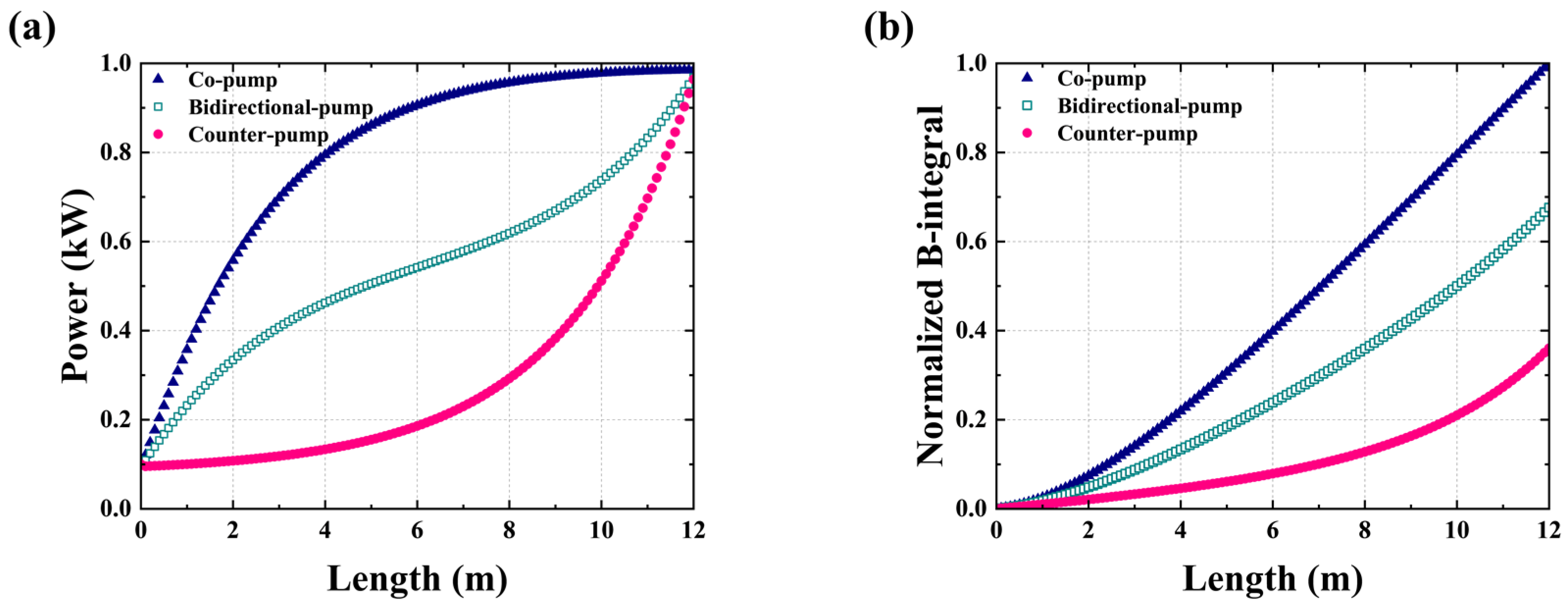
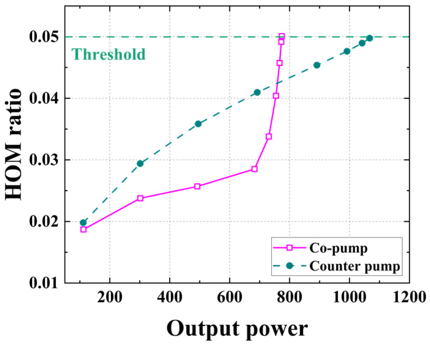
2.1. Nonlinear Effect (SRS) and TMI Suppression Based on Pump Optimization
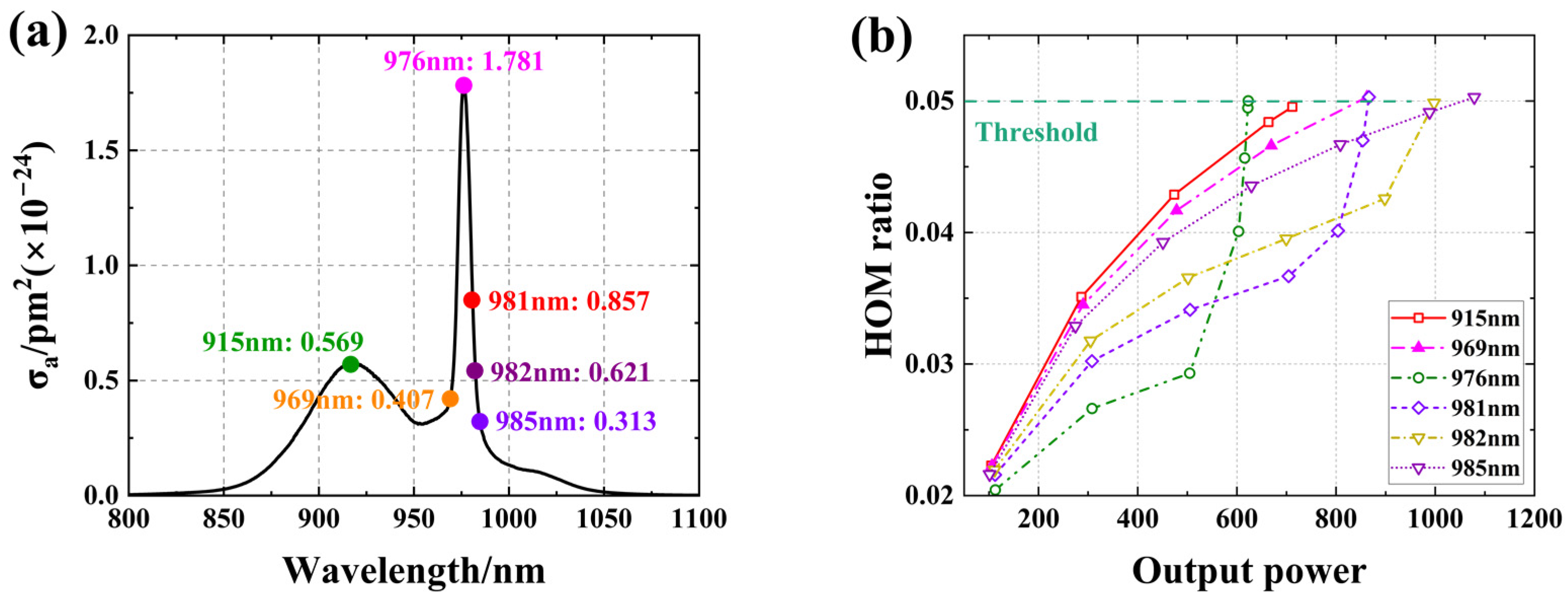
2.2. TMI Suppression Based on Pump Wavelength Optimization
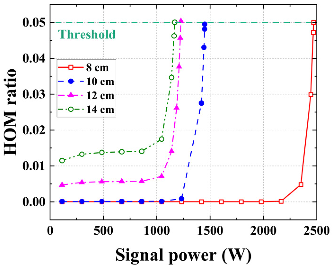
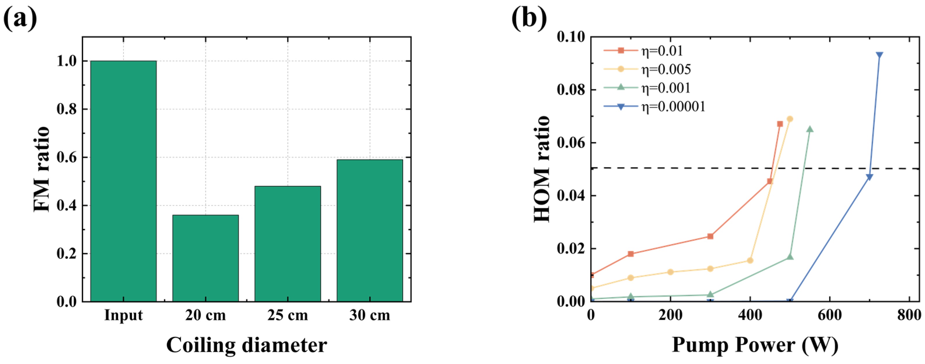
2.3. TMI Suppression Based on Fiber Coiling
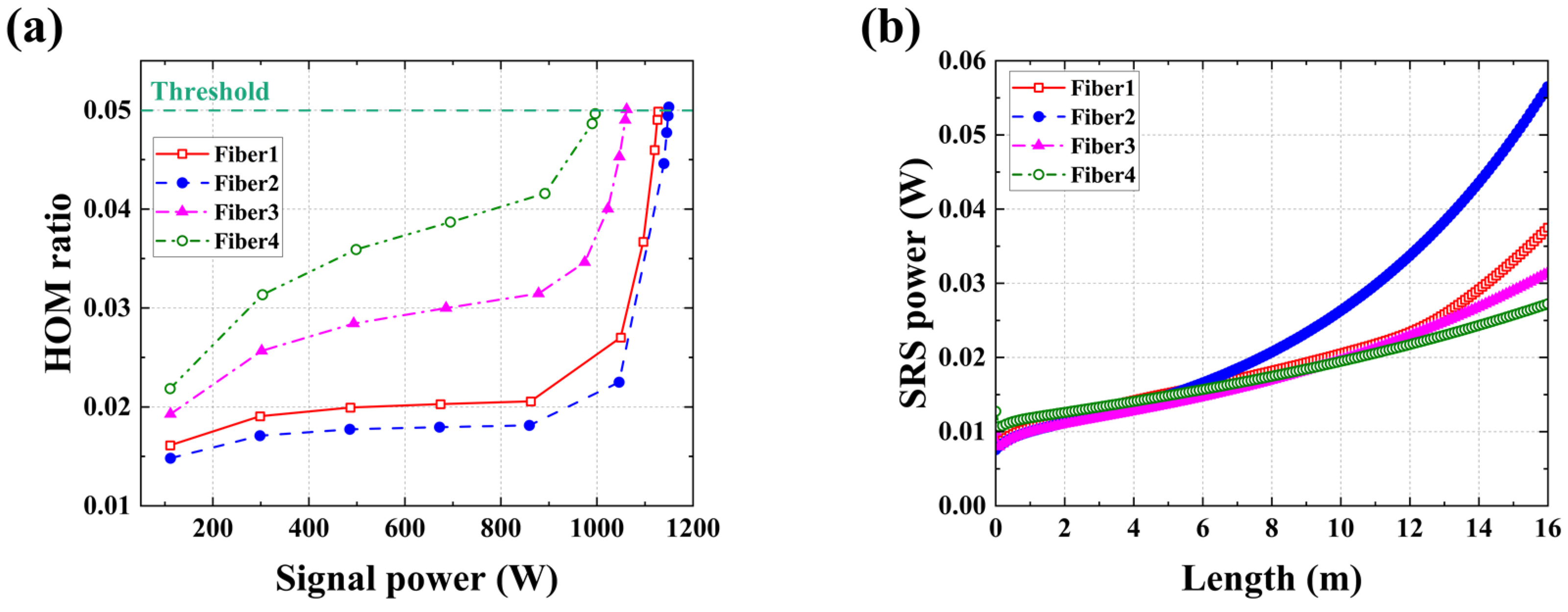
2.4. Balance TMI and SRS Based on Vary Core Diameter Active Fiber
2.5. Summary
3. Experimental Demonstration of These Measures on SRS and TMI Suppression in Direct LD Pumped Fiber Laser
3.1. SRS in Lasers under Different Pump Configurations
3.2. TMI Suppression by Optimizing Pump Wavelength
3.3. Abnormal TMI Suppression Method Based on Fiber Coiling
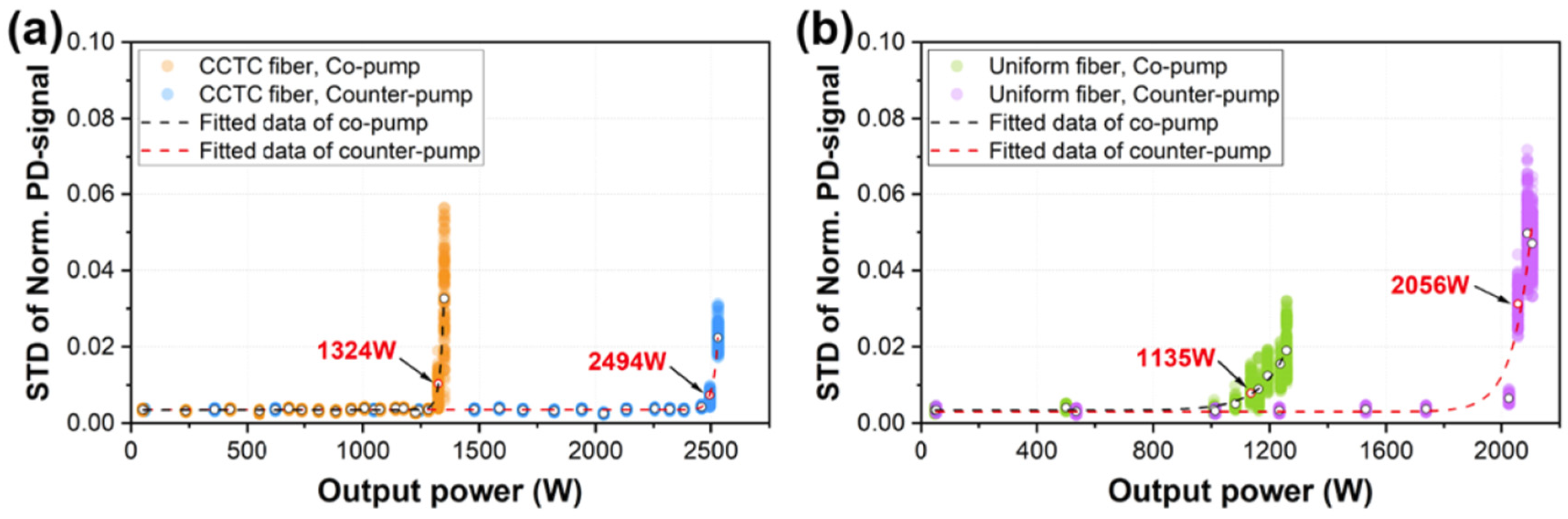
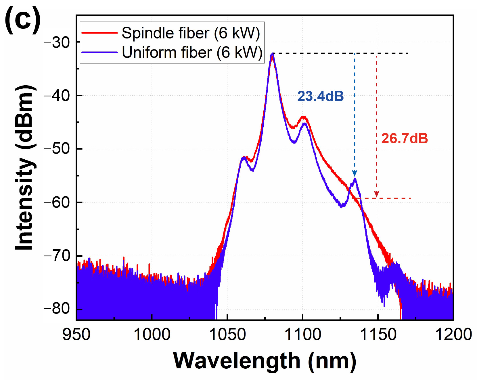
3.4. Balance TMI and SRS in Fiber Laser Amplifier Based on VCAF
3.5. Summary
4. Power Scaling of the Direct LD Pumped Fiber Laser Employing New Suppression Technology
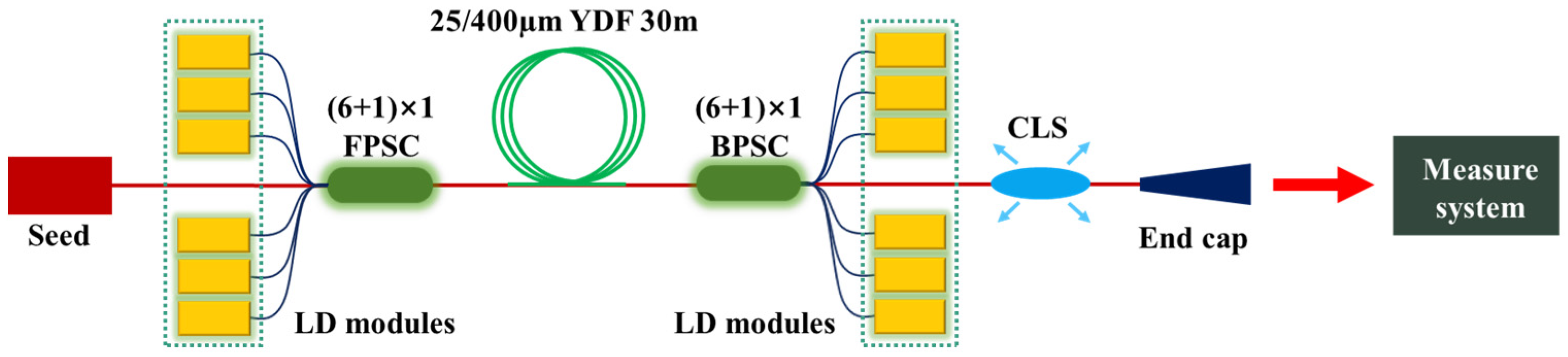
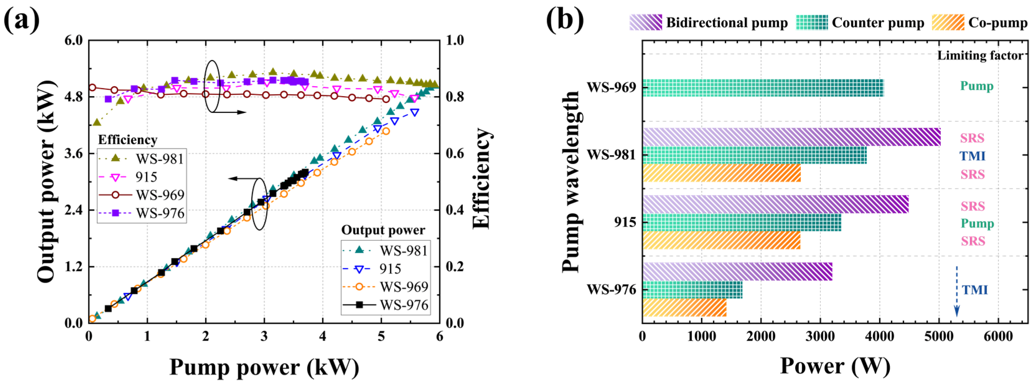
4.1. High-Power Fiber Oscillator Based on Pump Wavelength Optimization
4.1.1. WS-981 Bidirectional Pumped 5 kW Fiber Oscillator
4.1.2. WS-981 Counter Pumped 8 kW Fiber Oscillator
4.2. High Power Fiber Amplifier Based on Pump Wavelength Optimization
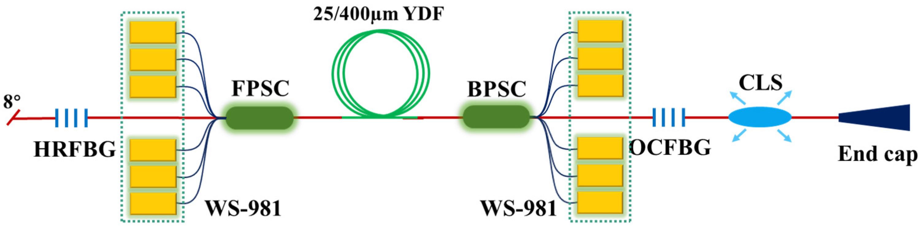
4.2.1. WS-981 Bidirectional Pumped 6 kW Fiber Amplifier
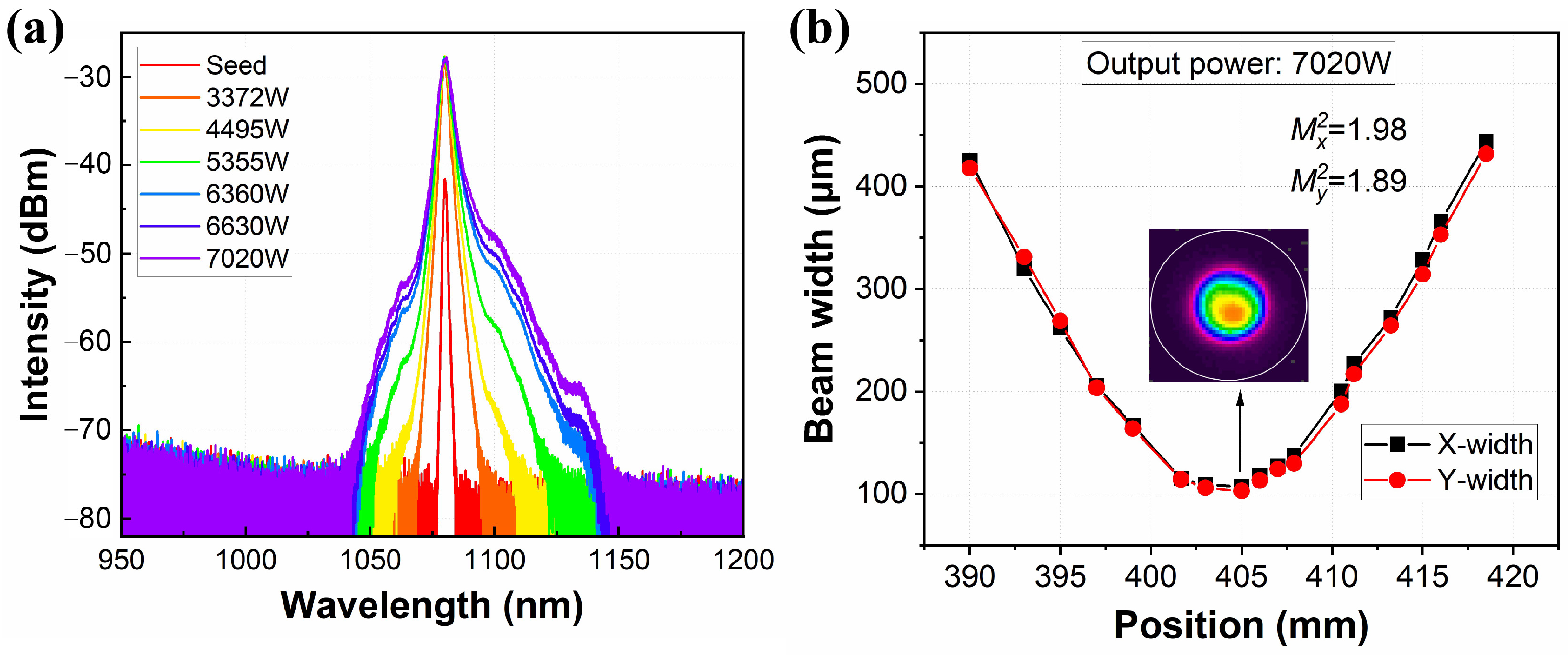
4.2.2. WS-981 Counter Pumped 7 kW Fiber Amplifier
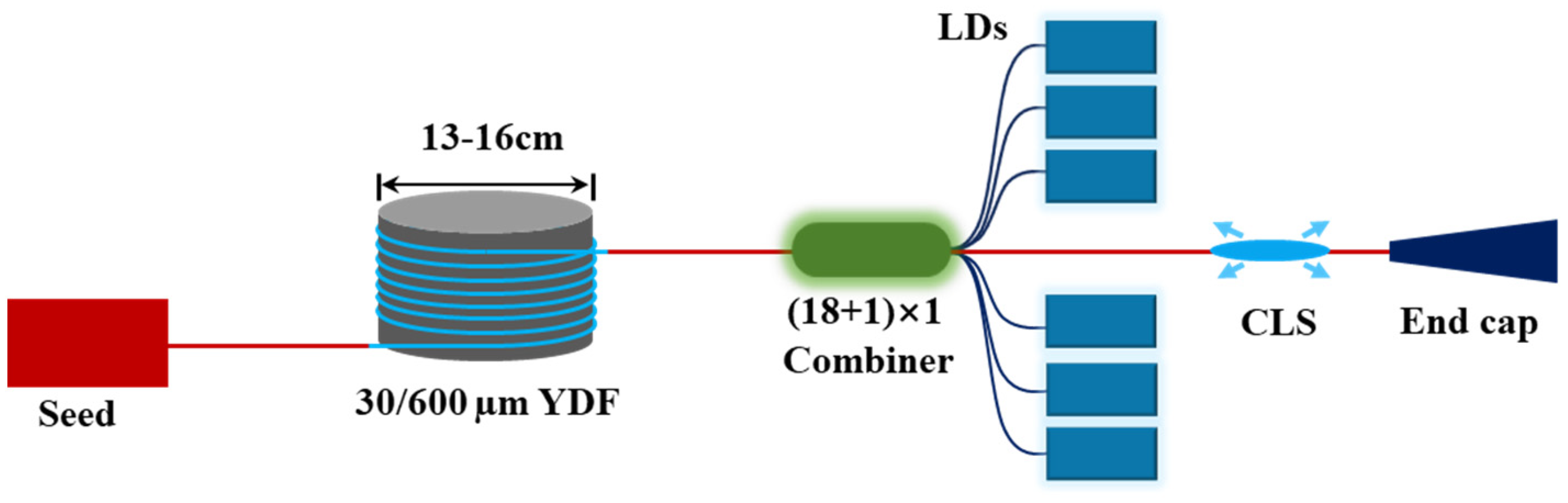
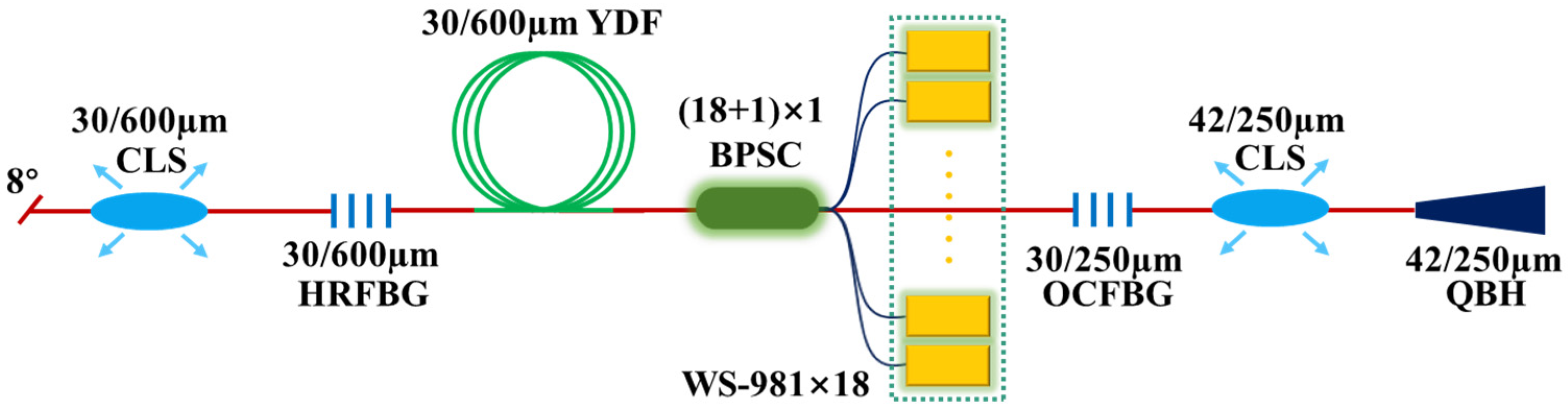
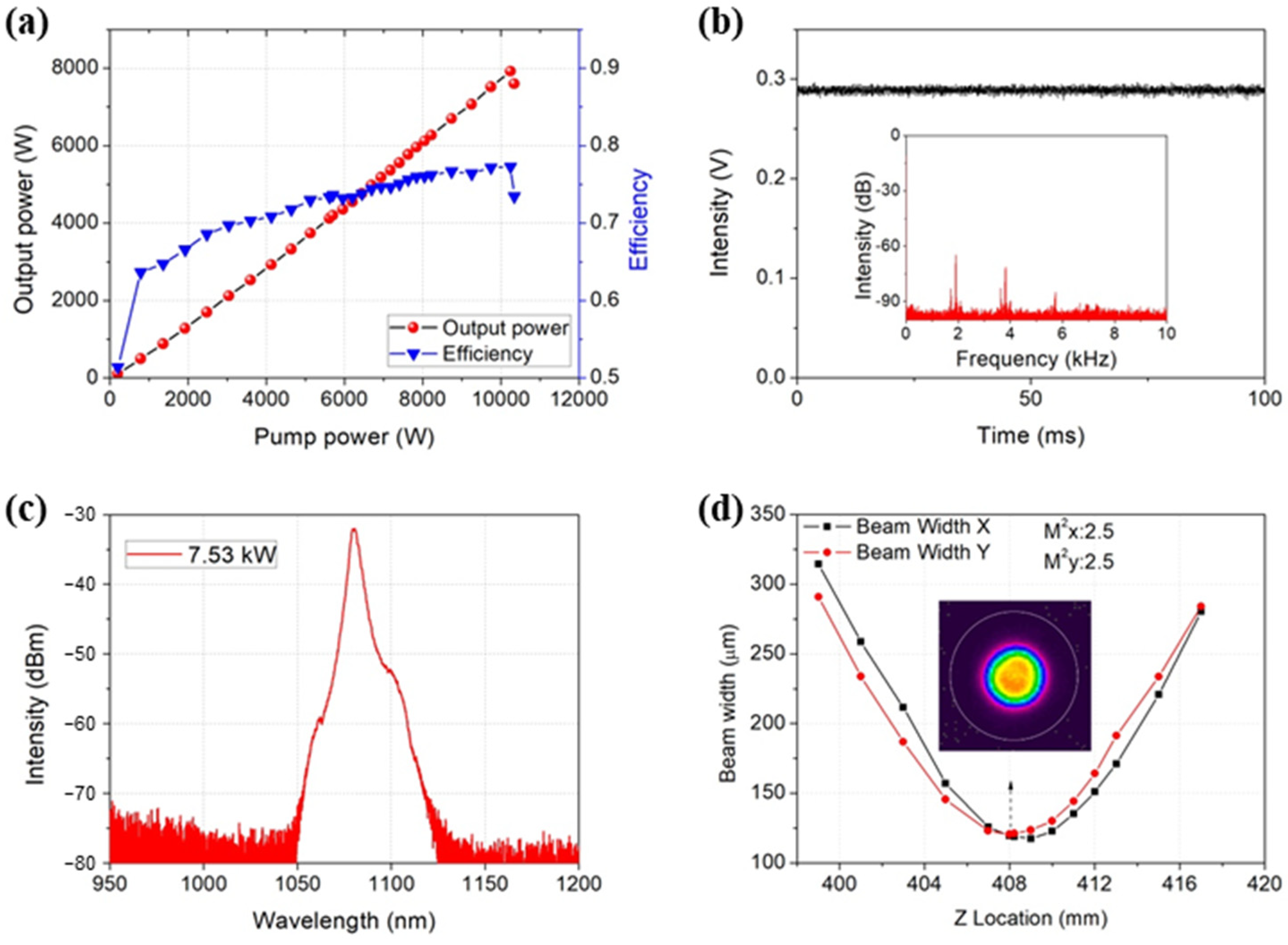
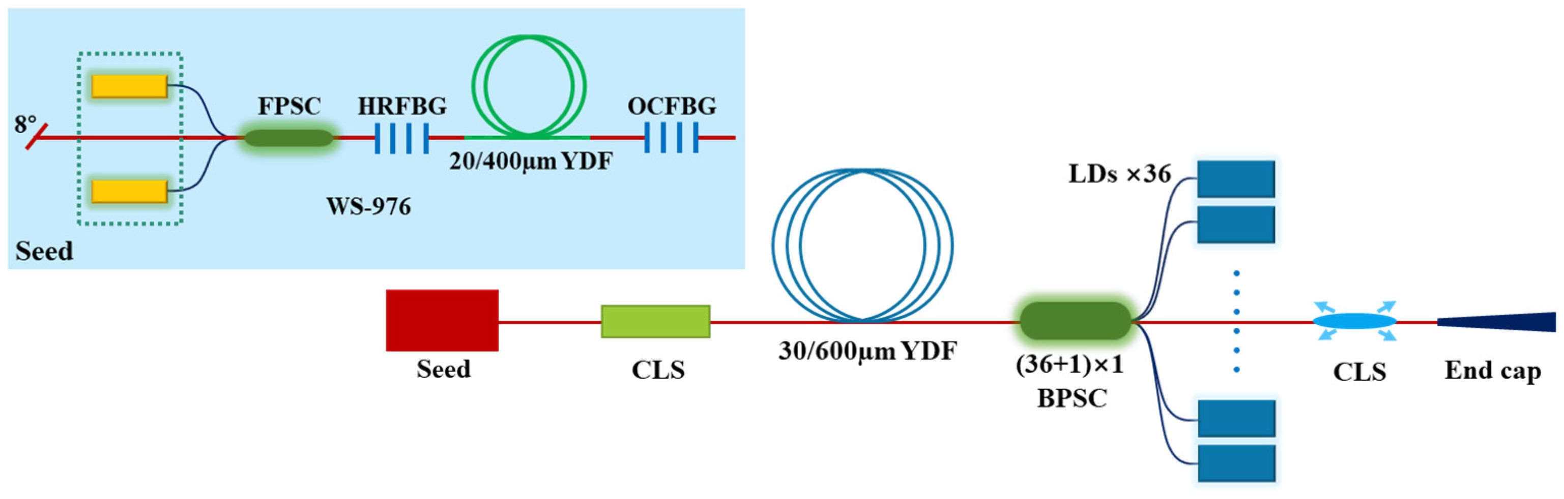
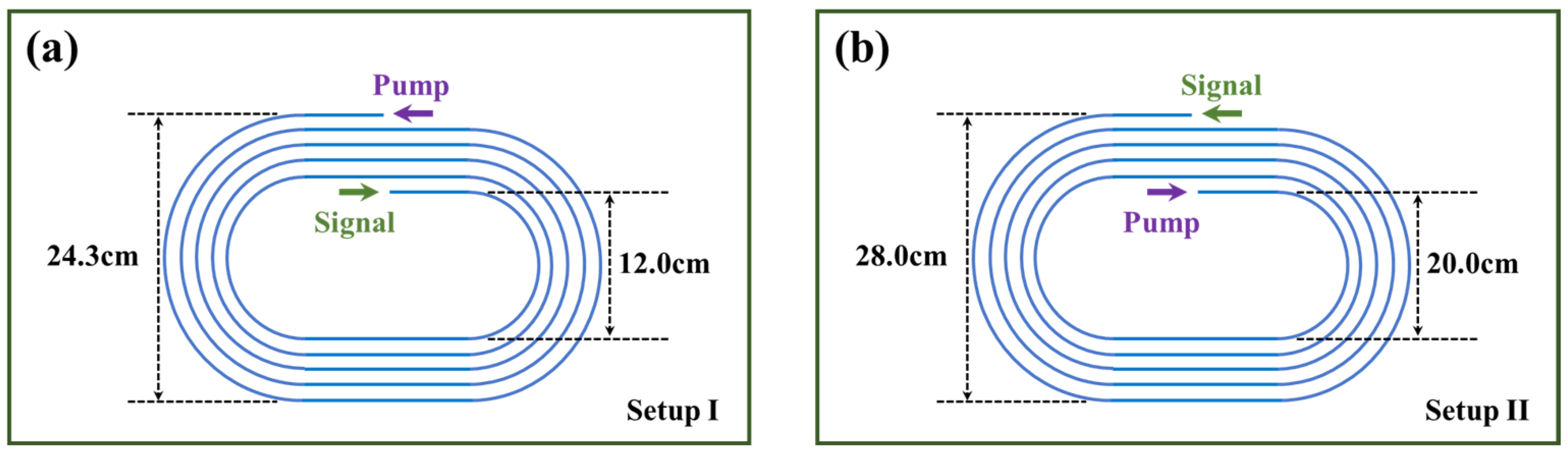
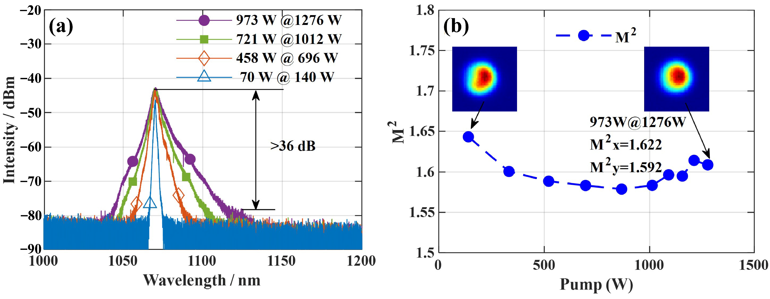
4.2.3. WS-976 Counter Pumped 10 kW Fiber Amplifier by Fiber Coiling Optimization
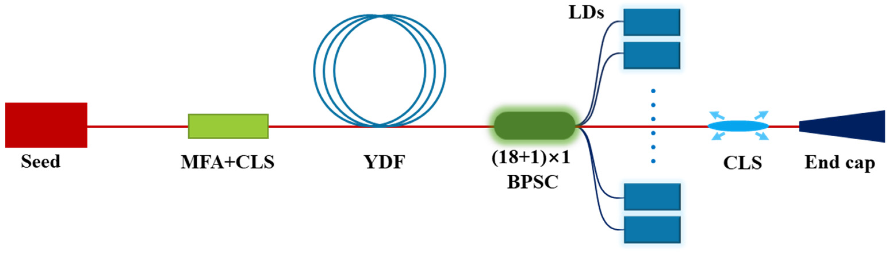
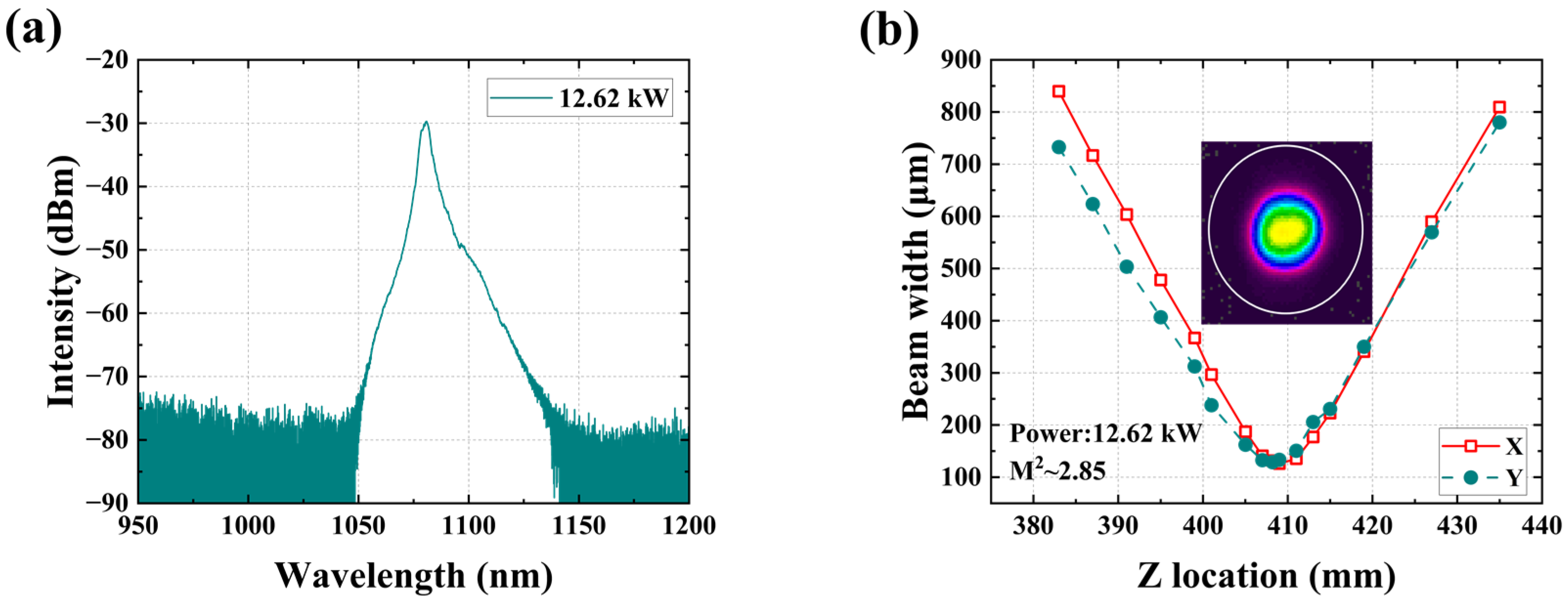
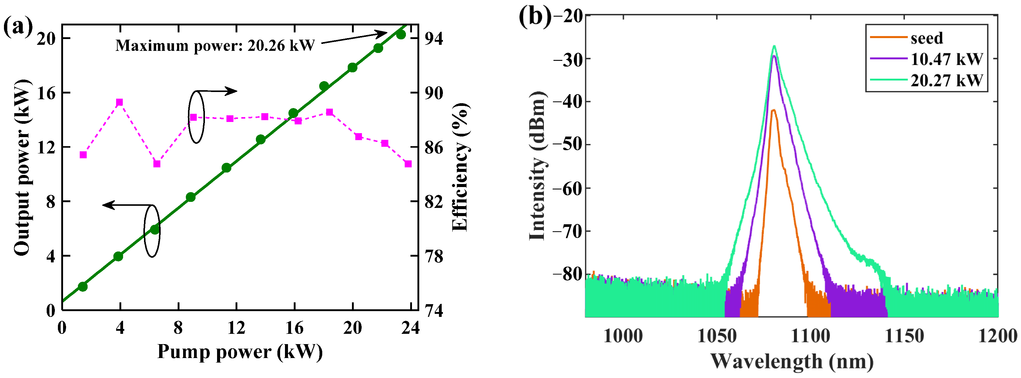
4.2.4. WS-981 Counter-Pumped Fiber Amplifiers with Power Exceeding 10 kW
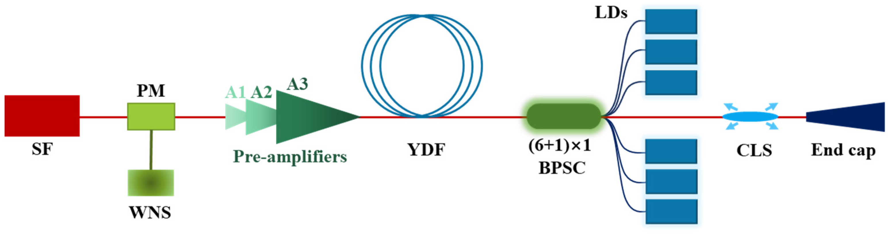
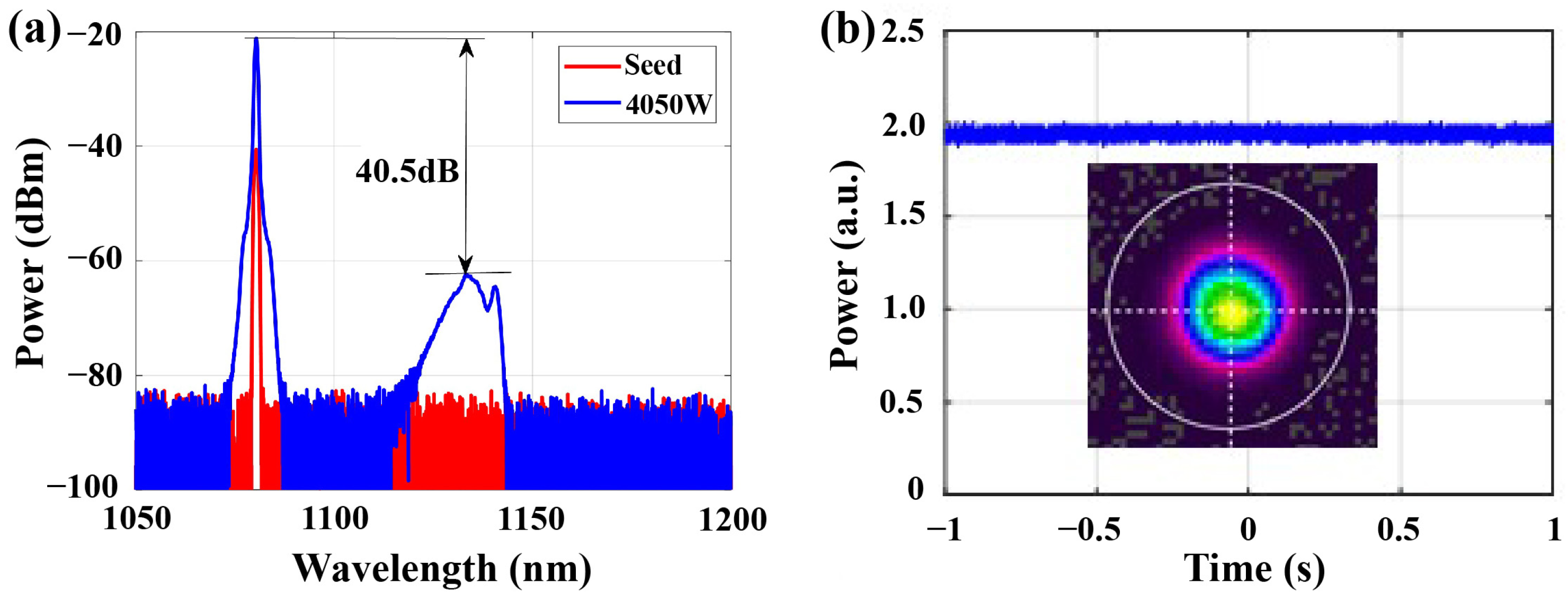
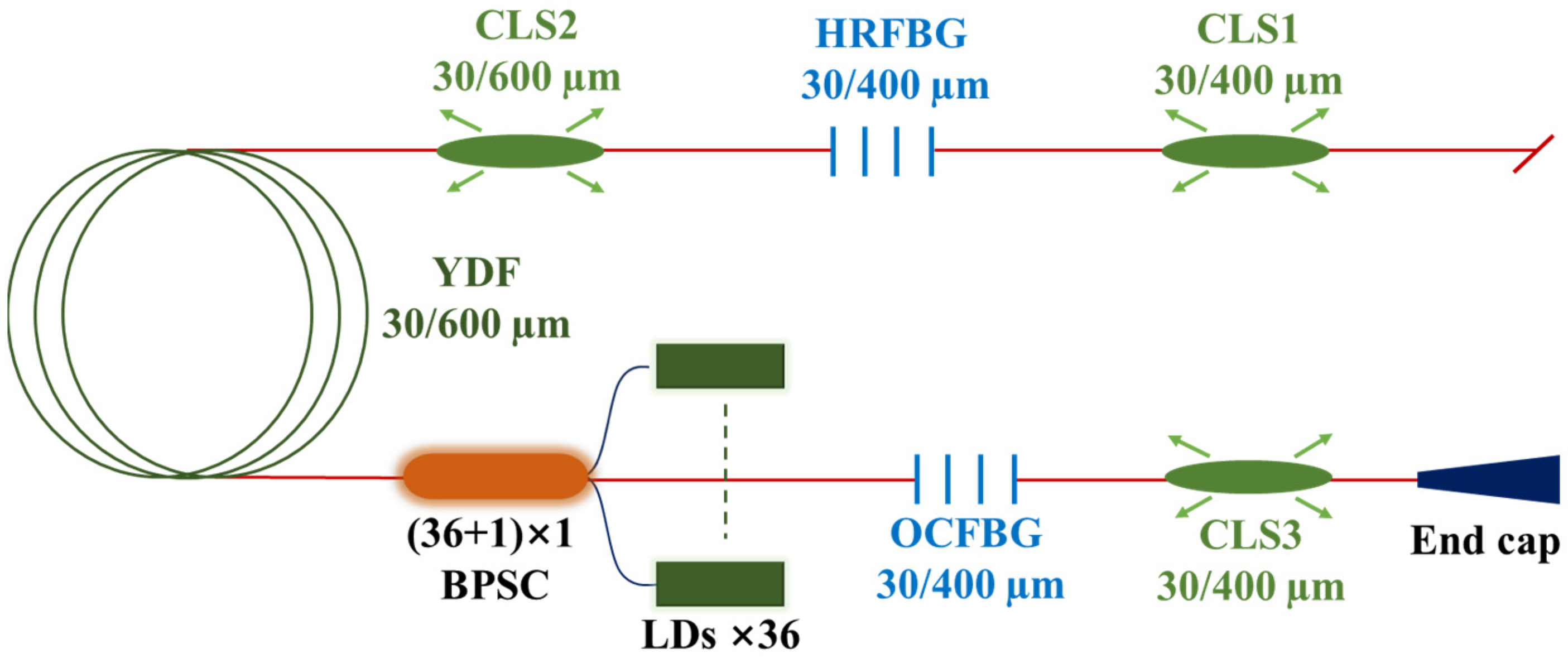
4.3. 4 kW High-Power Counter Pumped Narrow Linewidth Amplifier Based on Pump Wavelength Optimization
4.4. 10 kW QCW Fiber Laser Employing Counter Pump Configuration to Suppression SRS
4.5. Summary
5. Conclusions
Author Contributions
Funding
Institutional Review Board Statement
Informed Consent Statement
Data Availability Statement
Conflicts of Interest
References
- Jeong, Y.; Sahu, J.; Payne, D.; Nilsson, J. Ytterbium-doped large-core fiber laser with 1.36 kW continuous-wave output power. Opt. Express 2004, 12, 6088–6092. [Google Scholar] [CrossRef]
- Gapontsev, V.; Gapontsev, D.; Platonov, N.; Shkurikhin, O.; Ferin, S. 2 kW CW ytterbium fiber laser with record diffraction-limited brightness. In Proceedings of the Conference on Lasers & Electro-Optics Europe, Munich, Germany, 12–17 June 2005. [Google Scholar]
- Yu, H.; Zhang, H.; Lv, H.; Wang, X.; Leng, J.; Xiao, H.; Guo, S.; Zhou, P.; Xu, X.; Chen, J. 3.15 kW direct diode-pumped near diffraction-limited all-fiber-integrated fiber laser. Appl. Opt. 2015, 54, 4556–4560. [Google Scholar] [CrossRef] [PubMed]
- Fang, Q.; Li, J.; Shi, W.; Qin, Y.; Xu, Y.; Meng, X.; Norwood, R.A.; Peyghambarian, N. 5 kW Near-Diffraction-Limited and 8 kW High-Brightness Monolithic Continuous Wave Fiber Lasers Directly Pumped by Laser Diodes. IEEE Photonics J. 2017, 9, 1–7. [Google Scholar] [CrossRef]
- Wang, Y.; Gao, C.; Tang, X.; Zhan, H.; Peng, K.; Ni, L.; Liu, S.; Li, Y.; Guo, C.; Wang, X.; et al. 30/900 Yb-doped Aluminophosphosilicate Fiber Presenting 6.85-kW Laser Output Pumped With Commercial 976-nm Laser Diodes. J. Light. Technol. 2018, 36, 3396–3402. [Google Scholar] [CrossRef]
- Beier, F.; Möller, F.; Sattler, B.; Nold, J.; Liem, A.; Hupel, C.; Kuhn, S.; Hein, S.; Haarlammert, N.; Schreiber, T.; et al. Experimental investigations on the TMI thresholds of low-NA Yb-doped single-mode fibers. Opt. Lett. 2018, 43, 1291–1294. [Google Scholar] [CrossRef]
- Lin, H.; Xu, L.; Li, C.; Shu, Q.; Chu, Q.; Xie, L.; Guo, C.; Zhao, P.; Li, Z.; Wang, J.; et al. 10.6 kW high-brightness cascade-end-pumped monolithic fiber lasers directly pumped by laser diodes in step-index large mode area double cladding fiber. Results Phys. 2019, 14, 102479. [Google Scholar] [CrossRef]
- Wu, H.; Li, R.; Xiao, H.; Huang, L.; Yang, H.; Pan, Z.; Leng, J.; Zhou, P. High-power tandem-pumped fiber amplifier with beam quality maintenance enabled by the confined-doped fiber. Opt. Express 2021, 29, 31337. [Google Scholar] [CrossRef] [PubMed]
- Yang, B.; Wang, P.; Zhang, H.; Xi, X.; Shi, C.; Wang, X.; Xu, X. 6 kW single mode monolithic fiber laser enabled by effective mitigation of the transverse mode instability. Opt. Express 2021, 29, 26366. [Google Scholar] [CrossRef]
- Wen, Y.; Wang, P.; Xi, X.; Zhang, H.; Huang, L.; Yang, H.; Yan, Z.; Yang, B.; Shi, C.; Pan, Z.; et al. LD Direct Counter-Pumped 10 kW Fiber Laser Amplifier With Good Beam Quality. Acta Phys. Sin.-Ch. Ed. 2022, 71, 244202. [Google Scholar] [CrossRef]
- Xiao, Y.; Brunet, F.; Kanskar, M.; Faucher, M.; Wetter, A.; Holehouse, N. 1-kilowatt CW all-fiber laser oscillator pumped with wavelength-beam-combined diode stacks. Opt. Express 2012, 20, 3296–3301. [Google Scholar] [CrossRef] [PubMed]
- Yang, B.; Zhang, H.; Shi, C.; Wang, X.; Zhou, P.; Xu, X.; Chen, J.; Liu, Z.; Lu, Q. Mitigating transverse mode instability in all-fiber laser oscillator and scaling power up to 2.5 kW employing bidirectional-pump scheme. Opt. Express 2016, 24, 27828–27835. [Google Scholar] [CrossRef] [PubMed]
- Ackermann, M.; Rehmann, G.; Lange, R.; Witte, U.; Safarzadeh, F.; Boden, B.; Weber, H.; Netz, D.; Perne, C.; Kösters, A.; et al. Extraction of more than 10 kW from a single ytterbium-doped MM-fiber. In Fiber Lasers XVI: Technology and Systems; SPIE: San Francisco, CA, USA, 2019. [Google Scholar]
- Ye, Y.; Yang, B.; Wang, P.; Zeng, L.; Xi, X.; Shi, C.; Zhang, H.; Wang, X.; Zhou, P.; Xu, X. Industrial 6 kW high-stability single-stage all-fiber laser oscillator based on conventional large mode area ytterbium-doped fiber. Laser Phys. 2021, 31, 35104. [Google Scholar] [CrossRef]
- Wang, Y.; Rintaro, K.; Kiyoyama, W.; Shirakura, Y.; Kurihara, T.; Nakanishi, Y.; Yamamoto, T.; Nakayama, M.; Ikoma, S.; Shima, K. 8-kW single-stage all-fiber Yb-doped fiber laser with a BPP of 0.50 mm-mrad. In Fiber Lasers XVII: Technology and Systems; SPIE: San Francisco, CA, USA, 2020. [Google Scholar]
- Krmer, R.G.; Mller, F.; Matzdorf, C.; Goebel, T.A.; Nolte, S. Extremely robust femtosecond written fiber Bragg gratings for ytterbium doped fiber oscillator with 5 kW output power. Opt. Lett. 2020, 45, 1447–1450. [Google Scholar] [CrossRef] [PubMed]
- Zervas, M.N.; Codemard, C.A. High Power Fiber Lasers: A Review. IEEE J. Sel. Top. Quant. 2014, 20, 219–241. [Google Scholar] [CrossRef]
- Beyer, E.; Mahrle, A.; Lütke, M.; Standfuss, J.; Brückner, F. Innovations in high power fiber laser applications. In Fiber Lasers IX: Technology, Systems, and Applications; SPIE: San Francisco, CA, USA, 2012. [Google Scholar]
- Zervas, M.N. Transverse mode instability, thermal lensing and power scaling in Yb3+-doped high-power fiber amplifiers. Opt. Express 2019, 27, 19019–19041. [Google Scholar] [CrossRef]
- Jauregui, C.; Stihler, C.; Limpert, J. Transverse mode instability. Adv. Opt. Photonics 2020, 12, 429–484. [Google Scholar] [CrossRef]
- Eidam, T.; Hanf, S.; Seise, E.; Andersen, T.V.; Gabler, T.; Wirth, C.; Schreiber, T.; Limpert, J.; Tunnermann, A. Femtosecond fiber CPA system emitting 830 W average output power. Opt. Lett. 2010, 35, 94–96. [Google Scholar] [CrossRef]
- Stutzki, F.; Otto, H.J.; Jansen, F.; Gaida, C.; Jauregui, C.; Limpert, J.; Tunnermann, A. High-speed modal decomposition of mode instabilities in high-power fiber lasers. Opt. Lett. 2011, 36, 4572–4574. [Google Scholar] [CrossRef]
- Stutzki, F.; Jansen, F.; Eidam, T.; Steinmetz, A.; Jauregui, C.; Limpert, J.; Tünnermann, A. High average power large-pitch fiber amplifier with robust single-mode operation. Opt. Lett. 2011, 36, 689. [Google Scholar] [CrossRef]
- Smith, A.V.; Smith, J.J. Mode instability in high power fiber amplifiers. Opt. Express 2011, 19, 10180–10192. [Google Scholar] [CrossRef]
- Jauregui, C.; Eidam, T.; Limpert, J.; Tünnermann, A. The impact of modal interference on the beam quality of high-power fiber amplifiers. Opt. Express 2011, 19, 3258–3271. [Google Scholar] [CrossRef]
- Eidam, T.; Wirth, C.; Jauregui, C.; Stutzki, F.; Jansen, F.; Otto, H.; Schmidt, O.; Schreiber, T.; Limpert, J.; Tünnermann, A. Experimental observations of the threshold-like onset of mode instabilities in high power fiber amplifiers. Opt. Express 2011, 19, 13218–13224. [Google Scholar] [CrossRef] [PubMed]
- Hansen, K.R.; Alkeskjold, T.T.; Broeng, J.; Laegsgaard, J. Thermally induced mode coupling in rare-earth doped fiber amplifiers. Opt. Lett. 2012, 37, 2382–2384. [Google Scholar] [CrossRef] [PubMed]
- Jansen, F.; Stutzki, F.; Otto, H.; Eidam, T.; Liem, A.; Jauregui, C.; Limpert, J.; Tünnermann, A. Thermally induced waveguide changes in active fibers. Opt. Express 2012, 20, 3997–4008. [Google Scholar] [CrossRef]
- Jauregui, C.; Eidam, T.; Otto, H.; Stutzki, F.; Jansen, F.; Limpert, J.; Tünnermann, A. Physical origin of mode instabilities in high-power fiber laser systems. Opt. Express 2012, 20, 12912–12925. [Google Scholar] [CrossRef] [PubMed]
- Ward, B.; Robin, C.; Dajani, I. Origin of thermal modal instabilities in large mode area fiber amplifiers. Opt. Express 2012, 20, 11407–11422. [Google Scholar] [CrossRef]
- Beier, F.; Hupel, C.; Kuhn, S.; Hein, S.; Nold, J.; Proske, F.; Sattler, B.; Liem, A.; Jauregui, C.; Limpert, J.; et al. Single mode 4.3 kW output power from a diode-pumped Yb-doped fiber amplifier. Opt. Express 2017, 25, 14892–14899. [Google Scholar] [CrossRef] [PubMed]
- Yu, C.X.; Shatrovoy, O.; Fan, T.Y.; Taunay, T.F. Diode-pumped narrow linewidth multi-kilowatt metalized Yb fiber amplifier. Opt. Lett. 2016, 41, 5202–5205. [Google Scholar] [CrossRef] [PubMed]
- Dong, L.; Peng, X.; Li, J. Leakage channel optical fibers with large effective area. J. Opt. Soc. Am. B 2007, 24, 1689–1697. [Google Scholar] [CrossRef]
- Gu, G.; Kong, F.; Hawkins, T.; Parsons, J.; Jones, M.; Dunn, C.; Kalichevsky-Dong, M.T.; Saitoh, K.; Dong, L. Ytterbium-doped large-mode-area all-solid photonic bandgap fiber lasers. Opt. Express 2014, 22, 13962–13968. [Google Scholar] [CrossRef] [PubMed]
- Ma, X.; Zhu, C.; Hu, I.; Kaplan, A.; Galvanauskas, A. Single-mode chirally-coupled-core fibers with larger than 50 µm diameter cores. Opt. Express 2014, 22, 9206–9219. [Google Scholar] [CrossRef] [PubMed]
- Laurila, M.; Jørgensen, M.M.; Hansen, K.R.; Alkeskjold, T.T.; Broeng, J.; Lægsgaard, J. Distributed mode filtering rod fiber amplifier delivering 292W with improved mode stability. Opt. Express 2012, 20, 5742–5753. [Google Scholar] [CrossRef] [PubMed]
- Sanjabi, E.Z.; Antonio-Lopez, J.E.; Anderson, J.; Schulzgen, A.; Amezcua-Correa, R. Reduced-symmetry LMA rod-type fiber for enhanced higher-order mode delocalization. Opt. Lett. 2017, 42, 1974–1977. [Google Scholar] [CrossRef] [PubMed]
- Marciante, J.R. Gain Filtering for Single-Spatial-Mode Operation of Large-Mode-Area Fiber Amplifiers. IEEE J. Sel. Top. Quant. 2009, 15, 30–36. [Google Scholar] [CrossRef]
- Kokki, T.; Koponen, J.; Laurila, M.; Ye, C. Fiber amplifier utilizing an Yb-doped large-mode-area fiber with confined doping and tailored refractive index profile. In Fiber Lasers VII: Technology, Systems, and Applications; SPIE: San Francisco, CA, USA, 2010; pp. 758016–758019. [Google Scholar]
- Marciante, J.R.; Roides, R.G.; Shkunov, V.V.; Rockwell, D.A. Near-diffraction-limited operation of step-index large-mode-area fiber lasers via gain filtering. Opt. Lett. 2010, 35, 1828–1830. [Google Scholar] [CrossRef]
- Liao, L.; Zhang, F.; He, X.; Chen, Y.; Wang, Y.; Li, H.; Peng, J.; Yang, L.; Dai, N.; Li, J. Confined-doped fiber for effective mode control fabricated by MCVD process. Appl. Opt. Opt. Technol. Biomed. Opt. 2018, 57, 3244–3249. [Google Scholar] [CrossRef]
- Zhang, F.; Wang, Y.; Lin, X.; Cheng, Y.; Zhang, Z.; Liu, Y.; Li, J. Gain-tailored Yb/Ce codoped aluminosilicate fiber for laser stability improvement at high output power. Opt. Express 2019, 27, 20824–20836. [Google Scholar] [CrossRef]
- Huang, Z.; Shu, Q.; Luo, Y.; Tao, R.; Feng, X.; Liu, Y.; Lin, H.; Wang, J.; Jing, F. 3.5 kW narrow-linewidth monolithic fiber amplifier at 1064 nm by employing a confined doping fiber. J. Opt. Soc. Am. B 2021, 38, 2945–2952. [Google Scholar] [CrossRef]
- Jetschke, S.; Unger, S.; Schwuchow, A.; Leich, M.; Kirchhof, J. Efficient Yb laser fibers with low photodarkening by optimization of the core composition. Opt. Express 2008, 16, 15540–15545. [Google Scholar] [CrossRef]
- Jauregui, C.; Stutzki, F.; Tünnermann, A.; Limpert, J. Thermal analysis of Yb-doped high-power fiber amplifiers with Al:P co-doped cores. Opt. Express 2018, 26, 7614–7624. [Google Scholar] [CrossRef]
- Jetschke, S.; Unger, S.; Schwuchow, A.; Leich, M.; Jäger, M. Role of Ce in Yb/Al laser fibers: Prevention of photodarkening and thermal effects. Opt. Express 2016, 24, 13009–13022. [Google Scholar] [CrossRef]
- Hochheim, S.; Brockmuller, E.; Wessels, P.; Koponen, J.; Lowder, T.; Novotny, S.; Willke, B.; Neumann, J.; Kracht, D. Single-Frequency 336 W Spliceless All-Fiber Amplifier Based on a Chirally-Coupled-Core Fiber for the Next Generation of Gravitational Wave Detectors. J. Light. Technol. 2022, 40, 2136–2143. [Google Scholar] [CrossRef]
- Yuan, M.; Sui, Y.; Bai, Z.; Fan, Z. Recent Advances in Chirally-Coupled Core Fibers. Front. Phys. 2022, 10, 950492. [Google Scholar] [CrossRef]
- Smith, A.V.; Smith, J.J.; Ramachandran, S. Raising the mode instability thresholds of fiber amplifiers. In Fiber Lasers XI: Technology, Systems, and Applications; SPIE: San Francisco, CA, USA, 2014. [Google Scholar]
- Beier, F.; Hupel, C.; Nold, J.; Kuhn, S.; Hein, S.; Ihring, J.; Sattler, B.; Haarlammert, N.; Schreiber, T.; Eberhardt, R.; et al. Narrow linewidth, single mode 3 kW average power from a directly diode pumped ytterbium-doped low NA fiber amplifier. Opt. Express 2016, 24, 6011–6020. [Google Scholar] [CrossRef]
- Tao, R.; Su, R.; Ma, P.; Wang, X.; Zhou, P. Suppressing mode instabilities by optimizing the fiber coiling methods. Laser Phys. Lett. 2016, 14, 25101. [Google Scholar] [CrossRef]
- Zhu, S.; Li, J.; Li, L.; Sun, K.; Hu, C.; Shao, X.; Ma, X. Mode instabilities in Yb:YAG crystalline fiber amplifiers. Opt. Express 2019, 27, 35065–35078. [Google Scholar] [CrossRef] [PubMed]
- Jauregui, C.; Otto, H.; Stutzki, F.; Jansen, F.; Limpert, J.; Tünnermann, A. Passive mitigation strategies for mode instabilities in high-power fiber laser systems. Opt. Express 2013, 21, 19375–19386. [Google Scholar] [CrossRef] [PubMed]
- Brar, K.; Savage-Leuchs, M.; Henrie, J.; Courtney, S.; Dilley, C.; Afzal, R.; Honea, E.; Ramachandran, S. Threshold power and fiber degradation induced modal instabilities in high-power fiber amplifiers based on large mode area fibers. In Fiber Lasers XI: Technology, Systems, and Applications; SPIE: San Francisco, CA, USA, 2014; p. 89611R. [Google Scholar]
- Hejaz, K.; Norouzey, A.; Poozesh, R.; Heidariazar, A.; Roohforouz, A.; Rezaei Nasirabad, R.; Tabatabaei Jafari, N.; Hamedani Golshan, A.; Babazadeh, A.; Lafouti, M. Controlling mode instability in a 500 W ytterbium-doped fiber laser. Laser Phys. 2014, 24, 25102. [Google Scholar] [CrossRef]
- Tao, R.; Ma, P.; Wang, X.; Zhou, P.; Liu, Z. Study of wavelength dependence of mode instability based on a semi-analytical model. IEEE J. Quantum Elect. 2015, 51, 1600106. [Google Scholar]
- Tao, R.; Ma, P.; Wang, X.; Zhou, P.; Liu, Z. Mitigating of modal instabilities in linearly-polarized fiber amplifiers by shifting pump wavelength. J. Opt. 2015, 17, 45504. [Google Scholar] [CrossRef]
- Otto, H.; Modsching, N.; Jauregui, C.; Limpert, J.; Tünnermann, A.; Shaw, L.B. Wavelength dependence of maximal diffraction-limited output power of fiber lasers. In Advanced Solid State Lasers 2014; SPIE: Shanghai, China, 2015; p. 93441Y. [Google Scholar]
- Yang, B.; Zhang, H.; Wang, X.; Su, R.; Tao, R.; Zhou, P.; Xu, X.; Lu, Q. Mitigating transverse mode instability in a single-end pumped all-fiber laser oscillator with a scaling power of up to 2 kW. J. Opt. 2016, 18, 105803. [Google Scholar] [CrossRef]
- Jauregui, C.; Otto, H.; Breitkopf, S.; Limpert, J.; Tünnermann, A. Optimizing high-power Yb-doped fiber amplifier systems in the presence of transverse mode instabilities. Opt. Express 2016, 24, 7879–7892. [Google Scholar] [CrossRef] [PubMed]
- Wan, Y.; Xi, X.; Yang, B.; Zhang, H.; Wang, X. Enhancement of TMI Threshold in Yb-Doped Fiber Laser by Optimizing Pump Wavelength. IEEE Photonics Tech. Lett. 2021, 33, 656–659. [Google Scholar] [CrossRef]
- Wan, Y.; Yang, B.; Xi, X.; Zhang, H.; Wang, P.; Wang, X.; Xu, X. Comparison and Optimization on Transverse Mode Instability of Fiber Laser Amplifier Pumped by Wavelength-Stabilized and Non-Wavelength-Stabilized 976 nm Laser Diode. IEEE Photonics J. 2022, 14, 1503905. [Google Scholar] [CrossRef]
- Rezaei-Nasirabad, R.; Azizi, S.; Paygan, D.; Tavassoli, M.; Abedinajafi, A.; Roohforouz, A.; Chenar, R.E.; Golshan, A.H.; Hejaz, K.; Vatani, V. 2.5 kW TMI-free co-pump Yb-doped fiber oscillator by 971.5 nm pumping wavelength. Opt. Laser Technol. 2023, 157, 108652. [Google Scholar] [CrossRef]
- Naderi, S.; Dajani, I.; Grosek, J.; Madden, T.; Dinh, T.; Vodopyanov, K.L. Theoretical analysis of effect of pump and signal wavelengths on modal instabilities in Yb-doped fiber amplifiers. In Nonlinear Frequency Generation and Conversion: Materials, Devices, and Applications XIII; SPIE: San Francisco, CA, USA, 2014. [Google Scholar]
- Otto, H.; Jauregui, C.; Stutzki, F.; Jansen, F.; Limpert, J.; Tünnermann, A. Controlling mode instabilities by dynamic mode excitation with an acousto-optic deflector. Opt. Express 2013, 21, 17285–17298. [Google Scholar] [CrossRef]
- Jauregui, C.; Stihler, C.; Tünnermann, A.; Limpert, J. Pump-modulation-induced beam stabilization in high-power fiber laser systems above the mode instability threshold. Opt. Express 2018, 26, 10691–10704. [Google Scholar] [CrossRef]
- Lægsgaard, J. Static thermo-optic instability in double-pass fiber amplifiers. Opt. Express 2016, 24, 13429–13443. [Google Scholar] [CrossRef]
- Montoya, J.; Hwang, C.; Martz, D.; Aleshire, C.; Fan, T.Y.; Ripin, D.J. Photonic lantern kW-class fiber amplifier. Opt. Express 2017, 25, 27543–27550. [Google Scholar] [CrossRef] [PubMed]
- Zhou, P.; Xiao, H.; Leng, J.; Xu, J.; Chen, Z.; Zhang, H.; Liu, Z. High-power fiber lasers based on tandem pumping. J. Opt. Soc. Am. B 2017, 34, A29–A36. [Google Scholar] [CrossRef]
- Li, R.; Wu, H.; Xiao, H.; Leng, J.; Zhou, P. More than 5 kW counter tandem pumped fiber amplifier with near single-mode beam quality. Opt. Laser Technol. 2022, 153, 108204. [Google Scholar] [CrossRef]
- Wu, H.; Song, J.; Ma, P.; Liu, W.; Ren, S.; Wang, G.; Li, R.; Xiao, H.; Huang, L.; Leng, J.; et al. Bidirectional tandem-pumped high-brightness 6 kW level narrow-linewidth confined-doped fiber amplifier exploiting the side-coupled technique. Opt. Express 2022, 30, 21338–21348. [Google Scholar] [CrossRef]
- Wen, Y.; Wang, P.; Shi, C.; Yang, B.; Xi, X.; Zhang, H.; Wang, X. Experimental Study on Transverse Mode Instability Characteristics of Few-Mode Fiber Laser Amplifier Under Different Bending Conditions. IEEE Photonics J. 2022, 14, 1539106. [Google Scholar] [CrossRef]
- Zeng, L.; Xi, X.; Ye, Y.; Zhang, H.; Wang, X.; Pan, Z.; Wang, Z.; Xu, X. Near-single-mode 3 kW monolithic fiber oscillator based on a longitudinally spindle-shaped Yb-doped fiber. Opt. Lett. 2020, 45, 5792–5795. [Google Scholar] [CrossRef] [PubMed]
- Zeng, L.; Xi, X.; Ye, Y.; Lin, X.; Wang, X.; Li, J.; Shi, C.; Yang, B.; Zhang, H.; Wang, P.; et al. A novel fiber laser oscillator employing saddle-shaped core ytterbium-doped fiber. Appl. Phys. B 2020, 126, 185. [Google Scholar] [CrossRef]
- Ye, Y.; Lin, X.; Yang, B.; Xi, X.; Shi, C.; Zhang, H.; Wang, X.; Li, J.; Xu, X. Tapered Yb-doped fiber enabled a 4 kW near-single-mode monolithic fiber amplifier. Opt. Lett. 2022, 47, 2162–2165. [Google Scholar] [CrossRef]
- Ye, Y.; Lin, X.; Xi, X.; Zhang, H.; Yang, B.; Shi, C.; Wang, X.; Li, J.; Xu, X. Demonstration of constant-cladding tapered-core Yb-doped fiber for mitigating thermally-induced mode instability in high-power monolithic fiber amplifiers. Opt. Express 2022, 30, 24936–24947. [Google Scholar] [CrossRef] [PubMed]
- Ye, Y.; Lin, X.; Xi, X.; Zhang, H.; Wang, X.; Li, J.; Xu, X. Large mode area saddle-shaped core Yb-doped fiber enabled monolithic high-power, high-efficiency, near-diffraction-limited MOPA laser. In Proceedings of the Thirteenth International Conference on Information Optics and Photonics (CIOP 2022), Xi’an, China, 7–10 August 2022. [Google Scholar]
- Ye, Y.; Lin, X.; Xi, X.; Shi, C.; Yang, B.; Zhang, H.; Wang, X.; Li, J.; Xu, X. Novel constant-cladding tapered-core ytterbium-doped fiber for high-power fiber laser oscillator. High Power Laser Sci. 2021, 9, 142–148. [Google Scholar] [CrossRef]
- Zeng, L.; Pan, Z.; Xi, X.; Yang, H.; Ye, Y.; Huang, L.; Zhang, H.; Wang, X.; Wang, Z.; Zhou, P.; et al. 5 kW monolithic fiber amplifier employing homemade spindle-shaped ytterbium-doped fiber. Opt. Lett. 2021, 46, 1393–1396. [Google Scholar] [CrossRef]
- Lin, X.; Ye, Y.; Zhang, Z.; Wang, X.; Xing, Y.; Chen, G.; Peng, J.; Li, H.; Dai, N.; Li, J. 2.7 kW co-pumped fiber amplifier based on constant-cladding tapered-core fiber. Opt. Fiber Technol. 2022, 68, 102773. [Google Scholar] [CrossRef]
- Zhang, Z.; Lin, X.; Zhang, X.; Luo, Y.; Liao, S.; Wang, X.; Chen, G.; Xing, Y.; Li, H.; Peng, J.; et al. Low-numerical aperture confined-doped long-tapered Yb-doped silica fiber for a single-mode high-power fiber amplifier. Opt. Express 2022, 30, 32333–32346. [Google Scholar] [CrossRef]
- Glass, A.; Goodwin, E.; Trenholme, J. Characterization of optical nonlinearity in transparent dielectrics and implications for fusion laser design. IEEE J. Quantum Elect. 1975, 11, 850–851. [Google Scholar] [CrossRef]
- Perry, M.D.; Ditmire, T.; Stuart, B.C. Self-phase modulation in chirped-pulse amplification. Opt. Lett. 1994, 19, 2149–2151. [Google Scholar] [CrossRef]
- Smith, A.V.; Smith, J.J. Maximizing the Mode Instability Threshold of a Fiber Amplifier; Cornell University: Ithaca, NY, USA, 2013. [Google Scholar]
- Wan, Y.; Yang, B.; Wang, P.; Xi, X.; Zhang, H.; Wang, X. Optimizing the pump wavelength to improve the transverse mode instability threshold of fiber laser by 3.45 times. J. Mod. Optic. 2021, 68, 967–974. [Google Scholar] [CrossRef]
- Li, J.; Wang, J.; Jing, F. Improvement of Coiling Mode to Suppress Higher-Order-Modes by Considering Mode Coupling for Large-Mode-Area Fiber Laser. J. Electromagnet. Wave. 2010, 24, 1113–1124. [Google Scholar] [CrossRef]
- Chu, Q.; Tao, R.; Lin, H.; Wang, J.; Jing, F. Impact of bend-induced mode distortion on mode instability in high power fiber amplifiers. In Proceedings of the Sixth Symposium on Novel Optoelectronic Detection Technology and Applications, Beijing, China, 3–5 December 2019. [Google Scholar]
- Wan, Y.; Yang, B.; Xi, X.; Zhang, H.; Ye, Y.; Wang, X. Study on transverse mode instability of fiber lasers with different pump wavelengths. Infrared Laser Eng. 2021, 4, 196–203. [Google Scholar]
- Chu, Q.; Tao, R.; Li, C.; Lin, H.; Wang, Y.; Guo, C.; Wang, J.; Jing, F.; Tang, C. Experimental study of the influence of mode excitation on mode instability in high power fiber amplifier. Sci. Rep. 2019, 9, 9396. [Google Scholar] [CrossRef]
- Wu, H.; Li, H.; An, Y.; Li, R.; Chen, X.; Xiao, H.; Huang, L.; Yang, H.; Yan, Z.; Leng, J.; et al. Transverse mode instability mitigation in a high-power confined-doped fiber amplifier with good beam quality through seed laser control. High Power Laser Sci. 2022, 10, e44. [Google Scholar] [CrossRef]
- Zhang, F.; Xu, H.; Xing, Y.; Hou, S.; Chen, Y.; Li, J.; Dai, N.; Li, H.; Wang, Y.; Liao, L. Bending diameter dependence of mode instabilities in multimode fiber amplifier. Laser Phys. Lett. 2019, 16, 35104. [Google Scholar] [CrossRef]
- Zeng, L.; Wang, X.; Ye, Y.; Wang, L.; Yang, B.; Xi, X.; Wang, P.; Pan, Z.; Zhang, H.; Shi, C.; et al. High Power Ytterbium-Doped Fiber Lasers Employing Longitudinal Vary Core Diameter Active Fibers. Photonics 2023, 10, 147. [Google Scholar] [CrossRef]
- Ye, Y.; Yang, B.; Shi, C.; Xi, X.; Zhang, H.; Wang, X.; Zhou, P.; Xu, X. Towards power improvement of all-fiber laser oscillators with 30 μm-core Yb-doped fibers by suppressing transverse mode instability. Laser Phys. Lett. 2020, 17, 85106. [Google Scholar] [CrossRef]
- Wen, Y.; Wang, P.; Yang, B.; Zhang, H.; Xi, X.; Wang, X.; Xu, X. First Demonstration and Comparison of 5 kW Monolithic Fiber Laser Oscillator Pumped by 915 nm and 981 nm LDs. Photonics 2022, 9, 716. [Google Scholar] [CrossRef]
- Huang, Z.; Shu, Q.; Tao, R.; Chu, Q.; Luo, Y.; Yan, D.; Feng, X.; Liu, Y.; Wu, W.; Zhang, H.; et al. >5 kW Record High Power Narrow Linewidth Laser From Traditional Step-Index Monolithic Fiber Amplifier. IEEE Photonics Tech. Lett. 2021, 33, 1181–1184. [Google Scholar] [CrossRef]
- Ren, S.; Ma, P.; Li, W.; Wang, G.; Chen, Y.; Song, J.; Liu, W.; Zhou, P. 3.96 kW All-Fiberized Linearly Polarized and Narrow Linewidth Fiber Laser with Near-Diffraction-Limited Beam Quality. Nanomaterials 2022, 12, 2541. [Google Scholar] [CrossRef]
- Wang, G.; Song, J.; Chen, Y.; Ren, S.; Ma, P.; Liu, W.; Yao, T.; Zhou, P. Six kilowatt record all-fiberized and narrow-linewidth fiber amplifier with near-diffraction-limited beam quality. High Power Laser Sci. 2022, 10, e22. [Google Scholar] [CrossRef]
- Hong, Z.; Wan, Y.; Xi, X.; Zhang, H.; Wang, X.; Xu, X. High-peak-power pump-modulated quasi-CW fiber laser. Appl. Opt. 2022, 61, 1826–1833. [Google Scholar] [CrossRef]
- Wang, L.; Zhang, H.; Wang, P.; Yang, B.; Wang, X.; Ning, Y.; Xu, X. Theoretical and Experimental Study of High-Peak-Power High-Brightness Quasi-CW Fiber Laser. IEEE Photonics J. 2022, 14, 1530206. [Google Scholar] [CrossRef]
- Wang, L.; Zhang, H.; Wang, P.; Yang, B.; Wang, X.; Ning, Y.; Xu, X. A 6.4-kW peak power near-single-mode quasi-continuous wave fiber laser oscillator employing spindle-shaped ytterbium-doped fiber. Opt. Laser Technol. 2022, 154, 108338. [Google Scholar] [CrossRef]


| Parameters | Value |
|---|---|
| Core/Cladding diameter | 25/400 µm |
| Signal wavelength | 1080 nm |
| Seed power | 100 W |
| Pump wavelength | 976 nm |
| Length of active fiber | 12 m |
| Cladding pump absorption coefficient | 1.68 dB/m |
| Pump configuration (power) | co-pump (1000 W) Counter pump (1000 W) Bidirectional pump (500 W of co-pump and 500 W of Counter pump) |
| Parameter | Physical Meaning | Parameter | Physical Meaning |
|---|---|---|---|
| Initial high-order mode components | Gain distribution in lasers | ||
| Normalized mode field distribution of LP01 mode | Normalized mode field distribution of LP11 mode | ||
| Power distribution of LP01 mode | Second derivative of χ with respect to Ω | ||
| Relative intensity noise of input signal | Nonlinear coupling coefficient between LP01 and LP11 | ||
| L | The length of active fibers | Ω | Frequency shift between LP01 and LP11 |
| Ω0 | Maximum coupling frequency shift | r, ϕ | Transverse distribution of active fiber |
| Wavelength | 915 nm | 969 nm | 976 nm | 981 nm | 982 nm | 985 nm |
| TMI threshold (Signal) | 711 W | 862 W | 623 W | 866 W | 998 W | 1079 W |
| Quantum efficiency | 84.7% | 89.7% | 90.4% | 90.8% | 90.9% | 91.2% |
| Absorption cross section | 5.6932 × 10⁻²⁵ | 4.0733 × 10⁻²⁵ | 1.7669 × 10⁻²⁴ | 8.5664 × 10⁻²⁵ | 6.2079 × 10⁻²⁵ | 3.1281 × 10⁻²⁵ |
| Fiber | Core Diameter (Distribution) | Cladding Diameter (Distribution) | Length |
|---|---|---|---|
| Fiber1 | 20–30–20 µm | 400–600–600 µm | 16 m |
| Fiber2 | 20 µm | 400 µm | 16 m |
| Fiber3 | 25 µm | 500 µm | 16 m |
| Fiber4 | 30 µm | 600 µm | 16 m |
| Pump Wavelength | Coiling Diameter | M2 of Seed after Pass the Amplifier | M2 at Maximum Output Power | TMI Threshold | Brightness | Ratio |
|---|---|---|---|---|---|---|
| 976 nm | 13 cm | 1.58 | 2.24 | 1516 W | 259.0 | 1.00 |
| 14 cm | 1.73 | 2.23 | 1680 W | 289.6 | 1.11 | |
| 15 cm | 1.75 | 2.10 | 3130 W | 608.5 | 2.06 | |
| 16 cm | 1.85 | 2.04 | 4321 W | 890.2 | 2.85 | |
| 981 nm | 13 cm | 1.58 | 2.24 | 2788 W | 476.4 | 1.84 |
| 14 cm | 1.73 | 1.86 | 3975 W | 985.1 | 2.62 | |
| 15 cm | 1.79 | 2.06 | 6960 W | 1406.1 | 4.59 | |
| 16 cm | 1.87 | 2.17 | >7100 W | 1292.7 | >4.68 |
| Experimental Objectives | Experimental Parameters | Fiber Parameters |
|---|---|---|
| TMI comparison | WS-976 pump | Uniform fiber, 28/600 µm, core NA: 0.065, absorption coefficient: ~0.80 dB/m@976 nm |
| Spindle-shaped fiber, constant cladding diameter, (CCTC fiber in Figure 12) 20–36–20/600 µm, core NA: 0.065, absorption coefficient: ~0.78 dB/m@976 nm | ||
| SRS comparison | WS-981 pump | Uniform fiber, 25/400 µm, core NA: 0.060, absorption coefficient: ~0.81 dB/m@976 nm |
| Spindle-shaped fiber, constant core-to-cladding ratio, 25/400–37.5/600–25/400 µm, core NA: 0.060, absorption coefficient: 0.78 dB/m@976 nm |
| Setup | Minimum Coiling Diameter | Maximum Coiling Diameter | Maximum Power | Slope Efficiency | SRS | M2 | Brightness |
|---|---|---|---|---|---|---|---|
| I | 12.0 cm | 20.8 cm | 7310 W | 82.6% | 35.3 dB | 2.17 | 1330.9 |
| II | 11.0 cm | 20.0 cm | 7020 W | 79.3% | 36.7 dB | 1.93 | 1615.8 |
| Setup | Maximum Power | Efficiency | TMI | SRS | M2 | Brightness | Limiting Factor |
|---|---|---|---|---|---|---|---|
| I | 2543 W | 72.64% | 2467 W | >40 dB | 2.05; 1.91 | 556.8 | TMI |
| II | 10,530 W | 74.04% | >10,530 W | 30 dB | 2.83; 2.93 | 1088.7 | Pump power |
| Laser Type | Power | Pump Configuration | Pump Wavelength | M2 | SRS | Brightness |
|---|---|---|---|---|---|---|
| Fiber oscillator | 5 kW | Bidirectional pump | WS-981 | <1.4 | 32.5 dB | 2187.1 |
| 8 kW | Counter pump | WS-981 | 2.5 | >40 dB | 1097.4 | |
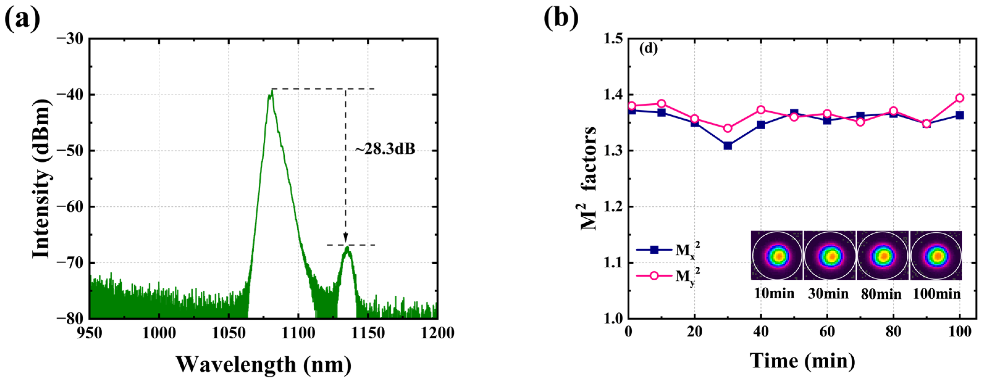
| Fiber amplifier | 6 kW | Bidirectional pump | WS-981 | 1.27 | 20 dB | 3189.3 |
| 7 kW | Counter pump | WS-981 | 1.93 | 36.7 dB | 1611.1 | |
| 10 kW | Counter pump | WS-976 | 2.88 | 30 dB | 1088.7 | |
| 12 kW | Counter pump | WS-981 | 2.85 | 37 dB | 1333.1 | |
| 20 kW | Counter pump | WS-981 | >7 | >40 dB | 262.4 | |
| Narrow-linewidth fiber amplifier | 4 kW | Counter pump | WS-981 | 1.3 | 40.5 dB | 2029.2 |
| QCW fiber oscillator | Peak 10 kW | Counter pump | WS-976 | 1.61 | 36 dB | 3555.6 |
Disclaimer/Publisher’s Note: The statements, opinions and data contained in all publications are solely those of the individual author(s) and contributor(s) and not of MDPI and/or the editor(s). MDPI and/or the editor(s) disclaim responsibility for any injury to people or property resulting from any ideas, methods, instructions or products referred to in the content. |
© 2023 by the authors. Licensee MDPI, Basel, Switzerland. This article is an open access article distributed under the terms and conditions of the Creative Commons Attribution (CC BY) license (https://creativecommons.org/licenses/by/4.0/).
Share and Cite
Zeng, L.; Wang, X.; Wang, L.; Ye, Y.; Wang, P.; Yang, B.; Xi, X.; Pan, Z.; Zhang, H.; Shi, C.; et al. Optimization and Demonstration of Direct LD Pumped High-Power Fiber Lasers to Balance SRS and TMI Effects. Photonics 2023, 10, 539. https://doi.org/10.3390/photonics10050539
Zeng L, Wang X, Wang L, Ye Y, Wang P, Yang B, Xi X, Pan Z, Zhang H, Shi C, et al. Optimization and Demonstration of Direct LD Pumped High-Power Fiber Lasers to Balance SRS and TMI Effects. Photonics. 2023; 10(5):539. https://doi.org/10.3390/photonics10050539
Chicago/Turabian StyleZeng, Lingfa, Xiaolin Wang, Li Wang, Yun Ye, Peng Wang, Baolai Yang, Xiaoming Xi, Zhiyong Pan, Hanwei Zhang, Chen Shi, and et al. 2023. "Optimization and Demonstration of Direct LD Pumped High-Power Fiber Lasers to Balance SRS and TMI Effects" Photonics 10, no. 5: 539. https://doi.org/10.3390/photonics10050539