Design of a Large Field of View and Low-Distortion Off-Axis Optical System Based on a Free-Form Surface


Abstract
:1. Introduction
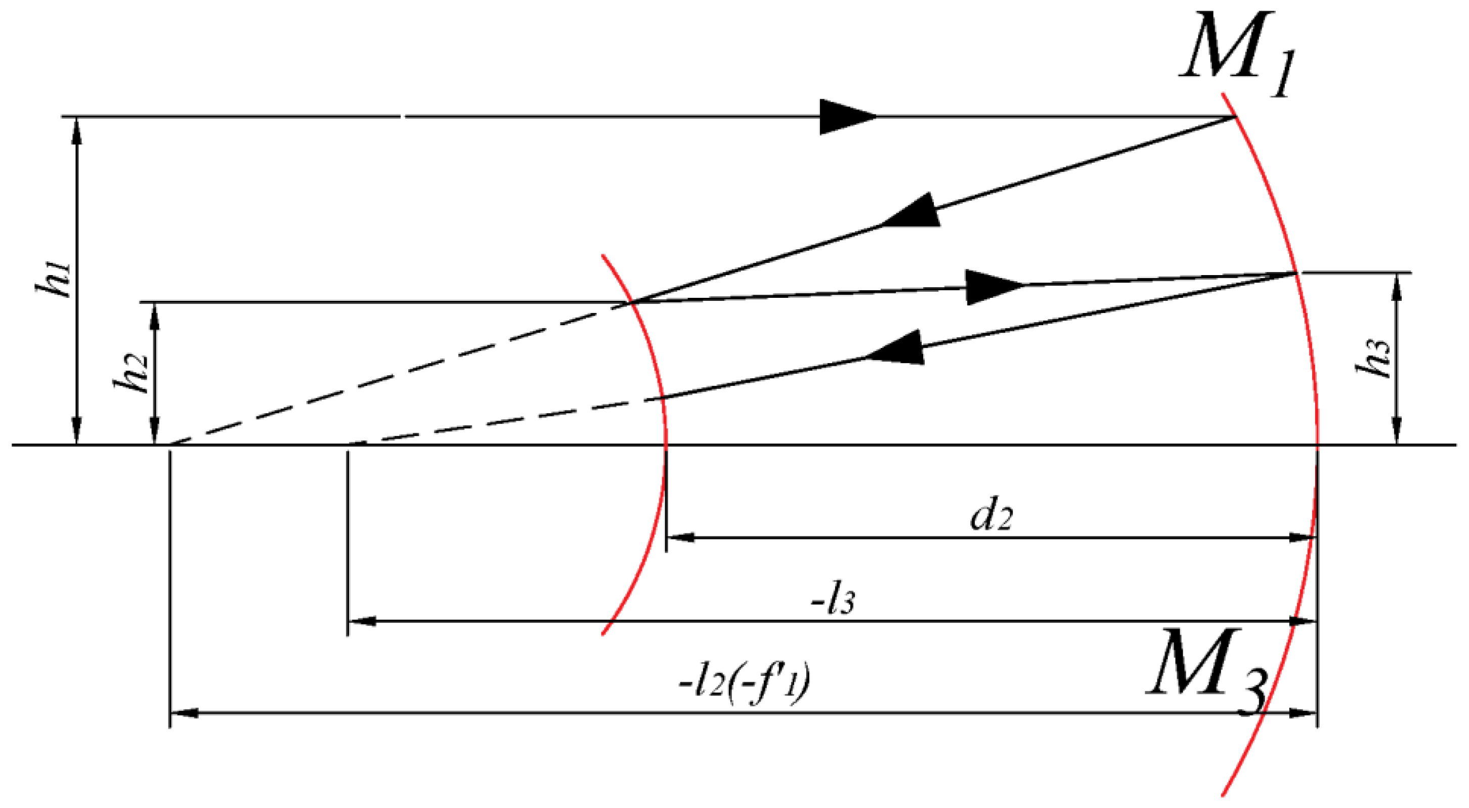
2. Optical System Design
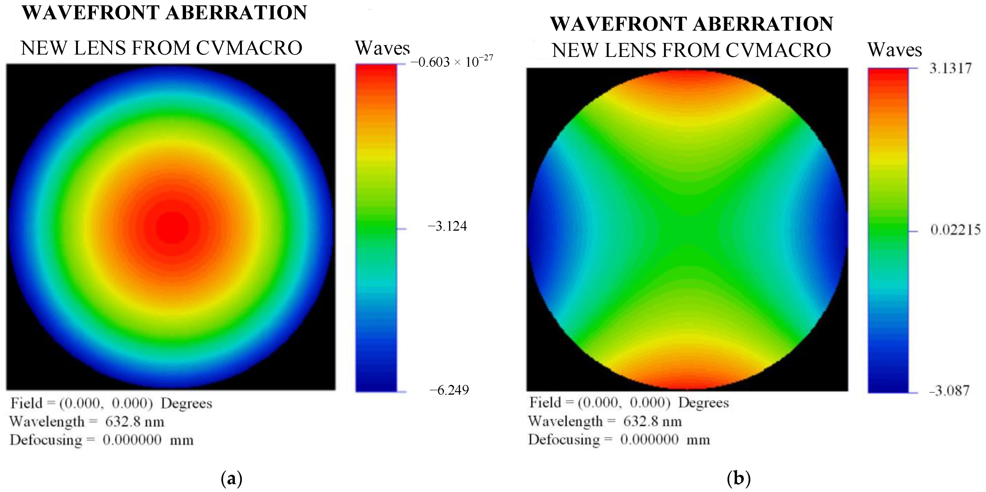
3. Quantitative Analysis of the Free-Form Surface
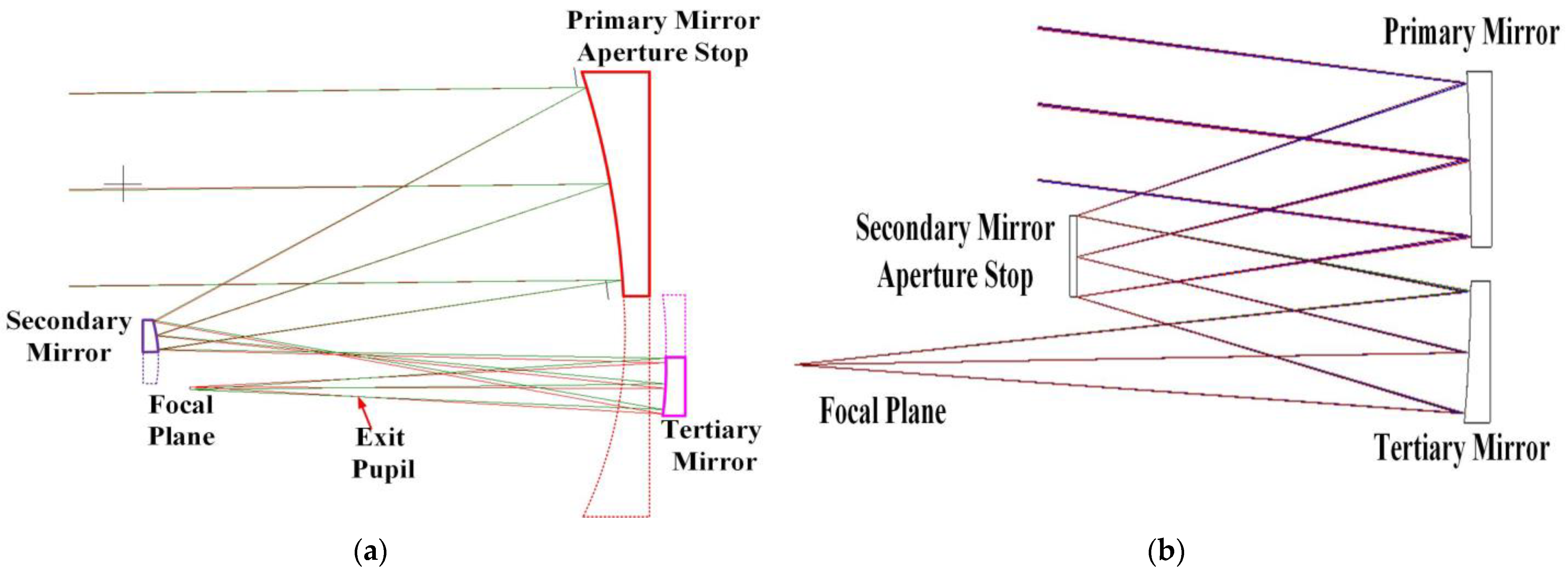
4. System Design and Analysis
4.1. Design Results
4.2. Tolerance Analysis
4.3. System Tolerance Analysis
5. Results and Discussion
Author Contributions
Funding
Institutional Review Board Statement
Informed Consent Statement
Data Availability Statement
Acknowledgments
Conflicts of Interest
References
- Gorevoy, A.V.; Machikhin, A.S.; Khokhlov, D.D.; Batshev, V.I. Optimization of prism-based stereoscopic imaging systems at the optical design stage with respect to required 3D measurement accuracy. Opt. Express 2020, 28, 24418–24430. [Google Scholar] [CrossRef] [PubMed]
- Kim, D.W.; Suratwala, T.I.; Schröder, S. Special Section Guest Editorial: Ultraprecision Optics Fabrication and Characterization. Opt. Eng. 2019, 58, 092601. [Google Scholar] [CrossRef]
- Yang, T.; Zhu, J.; Wu, X.F.; Jin, G.F. Direct design of freeform surfaces and freeform imaging systems with a point-by-point three-dimensional construction-iteration method. Opt. Express 2015, 23, 10233–10246. [Google Scholar] [CrossRef]
- Shen, Z.H. Design of Large Field of View Off-axis Three-mirror Reflective Optical System. Electro. Opt. Technol. Appl. 2020, 35, 24–27, 64. [Google Scholar] [CrossRef]
- Yan, J.H.; Hu, Z.J.; Zhu, D.Y. Design of Compact Off-axis Three-mirror Afocal System Based on Freeform Surface. Acta Photonica Sin. 2022, 51, 297–307. [Google Scholar] [CrossRef]
- Figoski, J.W. Alignment and test results of the QuickBird telescope using the Ball Optical System Test Facility. Proc. SPIE 1999, 3785, 99–108. [Google Scholar] [CrossRef]
- Nakajima, M.; Kojima, Y.; Moriyama, T. Mission overview and instrument concept of the Global Imager (GLI). In Proceedings of the SPIE’s 1994 International Symposium on Optics, Imaging, and Instrumentation, San Diego, CA, USA, 14 September 1994. [Google Scholar] [CrossRef]
- Mazzoli, A.; Holbrouck, P.; Houbrechts, Y.; Maresi, L.; Stockman, Y.; Taccola, M.; Versluys, J. Baffles design of the PROBA-V wide FOV TMA. In Proceedings of the International Conference on Space Optics—ICSO 2010, Rhodes Island, Greece, 20 November 2017. [Google Scholar] [CrossRef] [Green Version]
- Ohgi, N.; Iwasaki, A.; Kawashima, T.; Inada, H. Japanese hyper-multi spectral mission. In Proceedings of the 2010 IEEE International Geoscience and Remote Sensing Symposium, Honolulu, HI, USA, 25–30 July 2010; pp. 3756–3759. [Google Scholar] [CrossRef]
- Hugot, E.; Wang, X.; Valls-Gabaud, D.; Lemaître, G.; Agócs, T.; Wang, J.Y. A freeform-based, fast, wide-field, and distortion-free camera for ultralow surface brightness surveys. Proc. SPIE 2014, 9143, 9143X. [Google Scholar] [CrossRef]
- Liu, Y.X.; Zhang, D.D.; Niu, X.H. Design of Multi-spectrum Push-broom optical system. Opt. Tech. 2022, 48, 139–143. [Google Scholar] [CrossRef]
- Miao, L.; Zhu, L.; Fang, C.; Yan, N.; Yang, X.; Zhang, X. Modeling and Analysis of System Error for Highly Curved Freeform Surface Measurement by Noncontact Dual-Axis Rotary Scanning. Sensors 2021, 21, 554. [Google Scholar] [CrossRef] [PubMed]
- Fang, F.Z.; Zhang, X.D.; Weckenmann, A.; Zhang, G.X.; Evans, C. Manufacturing and measurement of freeform optics. CIRP Ann. Manuf. Technol. 2013, 62, 823–846. [Google Scholar] [CrossRef]
- Chen, S.Y.; Xue, S.; Zhai, D.D.; Tie, G.P. Measurement of Freeform Optical Surfaces: Trade-Off between Accuracy and Dynamic Range. Laser Photonics Rev. 2020, 14, 1900365. [Google Scholar] [CrossRef]
- Ma, T.; Yu, J.C.; Liang, P.; Wang, C.H. Design of a freeform varifocal panoramic optical system with specified annular center of field of view. Opt. Express 2011, 19, 3843–3853. [Google Scholar] [CrossRef]
- Zhu, J.; Hou, W.; Zhang, X.D.; Jin, G.F. Design of a low F-number freeform off-axis three-mirror system with rectangular field-of-view. J. Opt. 2015, 17, 015605. [Google Scholar] [CrossRef]
- Pan, J.W.; Che-Wen, C.; Huang, K.D.; Wu, C.Y. Demonstration of a broad band spectral head-mounted display with freeform mirrors. Opt. Express 2014, 22, 12785–12798. [Google Scholar] [CrossRef] [Green Version]
- Schober, C.; Beisswanger, R.; Gronle, A.; Pruss, C.; Osten, W. Tilted Wave Fizeau Interferometer for flexible and robust asphere and freeform testing. Light Adv. Manuf. 2022, 3, 48. [Google Scholar] [CrossRef]
- Schiesser, E.M.; Bauer, A.; Rolland, J.P. Effect of freeform surfaces on the volume and performance of unobscured three mirror imagers in comparison with off-axis rotationally symmetric polynomials. Opt. Express 2019, 27, 21750–21765. [Google Scholar] [CrossRef] [PubMed]
- Zhang, B.Q.; Jin, G.F.; Zhu, J. Towards automatic freeform optics design: Coarse and fine search of the three-mirror solution space. Light Sci. Appl. 2021, 10, 65. [Google Scholar] [CrossRef]
- Ye, G.F.; Chen, L.; Li, X.H.; Yuan, Q.; Gao, Z.S. Review of optical freeform surface representation technique and its application. Opt. Eng. 2017, 56, 110901. [Google Scholar] [CrossRef]
- Sun, Y.H.; Sun, Y.Q.; Chen, X.Y.; Wang, F.; Yan, X.; Zhang, X.N.; Cheng, T.L. Design of a free-form off-axis three-mirror optical system with a low f-number based on the same substrate. Appl. Opt. 2022, 61, 7033–7040. [Google Scholar] [CrossRef] [PubMed]
- Reimers, J.; Bauer, A.; Thompson, K.; Rolland, J. Freeform spectrometer enabling increased compactness. Light Sci Appl. 2017, 6, e17026. [Google Scholar] [CrossRef] [PubMed]
- Zhang, X.; Zheng, L.G.; He, X.; Wang, L.G.; Zhang, F.; Yu, S.Q.; Shi, G.W.; Zhang, B.Z.; Liu, Q.; Wang, T.T. Design and fabrication of imaging optical systems with freeform surfaces. Proc. SPIE 2012, 8486, 46–55. [Google Scholar] [CrossRef]
- Meng, Q.Y.; Wang, W.; Ma, H.T.; Dong, J.H. Easy-aligned off-axis three-mirror system with wide field of view using freeform surface based on integration of primary and tertiay mirror. Appl. Opt. 2014, 53, 3028–3034. [Google Scholar] [CrossRef] [PubMed] [Green Version]
- Chang, J.; Weng, Z.C.; Cong, X.J. Design of compact high-resolution optical system for space and stray-light analysis. Proc. SPIE 2022, 4927, 71–76. [Google Scholar] [CrossRef]
- Ni, D.W.; Li, X.Y.; Ren, Z.G.; Wang, Y.M.; Wang, L.; Tian, C.L. Design of off-axis three-mirror freeform optical system with wide field of view. Proc. SPIE 2019, 10837, 108370Z. [Google Scholar] [CrossRef]
- Cook, L.G. Three mirror anastigmatic optical system. U.S. Patent 4265510, 5 May 1981. [Google Scholar]
- Rodgers, J.M. Unobscured mirror designs. In Proceedings of the International Optical Design Conference 2002, Tucson, AZ, USA, 3–5 June 2002. [Google Scholar] [CrossRef]
- Yang, T.; Ye, Y.Z.; Cheng, D.W. Freeform Imaging Optical System Design: Theories, Development, and Applications. Acta Opt. Sin. 2021, 41, 0108001. [Google Scholar] [CrossRef]
- Kirschstein, S.; Koch, A.; Schöneich, J.; Döngi, F. Metal mirror TMA, telescopes of Jena spaceborne scanners: Design and analysis. Proc. SPIE 2005, 5962, 59621M. [Google Scholar] [CrossRef]
- Atchison, D.A.; Scott, D.H.; Cox, M.J. Mathematical treatment of ocular aberrations: A user’s guide. In Vision Science and Its Applications; Lakshminarayanan, V., Ed.; Optica Publishing Group: Santa Fe, NM, USA, 2000; pp. 110–130. [Google Scholar] [CrossRef]


| No. | Aberration | Radial Coordinate | Cartesian Coordinate |
|---|---|---|---|
| 1 | Piston | 1 | 1 |
| 2 | Tilt (X) | Rcos θ | X |
| 3 | Tilt (Y) | Rsin θ | Y |
| 4 | Defocus | 2R2 − 1 | 2X2 + 2Y2 − 1 |
| 5 | Astig (0°) | R2cos (2θ) | X2 − Y2 |
| 6 | Astig (45°) | R2sin (2θ) | 2XY |
| 7 | Coma (X) | (3R3 − 2R)cos θ | 3X3 + 3XY2 − 2X |
| 8 | Coma (Y) | (3R3 − 2R)sin θ | 3X2Y + 3Y3−2Y |
| 9 | Spherical | 6R4 − 6R2 + 1 | 6X4 + 12 X2Y2 + 6Y4 − 6X2 − 6Y2 + 1 |
| 10 | Trefoil (X) | R3cos (3θ) | X3 − 3XY2 |
| 11 | Trefoil (Y) | R3sin (3θ) | 3X2Y − Y3 |
| No. | Aberrations | Coefficient | Value | X–Y Polynomial Combinations | Coefficient | Value |
|---|---|---|---|---|---|---|
| 1 | Piston | 0 | 0 | 0 | 0 | 0 |
| 2 | Tilt (X) | 0 | 0 | A10 | 0 | 0 |
| 3 | Tilt (Y) | 0 | 0 | A01 | 0 | 0 |
| 4 | Defocus | 1 × 10⁻³ | −6.3209 | 2A20 + 2A02 | 1 × 10⁻³ | Piston: −3.1605 Defocus: −3.129 |
| 5 | Astig (0°) | 1 × 10⁻³ | −3.1531 | A20 − A02 | 1 × 10⁻³ | −3.1534 |
| 6 | Astig (45°) | 1 × 10⁻³ | −3.1530 | 2A11 | 1 × 10⁻³ | −3.1528 |
| 7 | Coma (X) | 1 × 10⁻³ | Tilt (X): −6.322 Coma(X): −3.105 | 3A30 + 3A12 − 2A10 | 1 × 10⁻³ | Tilt (X): −6.322 Coma(X): −3.105 |
| 8 | Coma (Y) | 1 × 10⁻³ | Tilt (Y): −6.322 Coma(Y): −3.105 | 3A21 + 3A03 − 2A01 | 1 × 10⁻³ | Tilt (X): −6.322 Coma(X): −3.105 |
| 9 | Spherical | 1 × 10⁻³ | Piston: 3.1604 Spherical: −3.146 | 6A40 + 12A22 + 6A04 − 6A20 − A02 | 1 × 10⁻³ | Piston: 3.1446 Spherical: −3.146 |
| 10 | Trefoil (X) | 1 × 10⁻³ | −3.1547 | A30 − 3A12 | 1 × 10⁻³ | −3.1548 |
| 11 | Trefoil (Y) | 1 × 10⁻³ | −3.1547 | 3A21 − A03 | 1 × 10⁻³ | −3.1548 |
| No. | Parameter | Value |
|---|---|---|
| 1 | Focal length (mm) | 1000 |
| 2 | F# | 9.5 |
| 3 | FOV (°) | 23 × 1 |
| 4 | Spectrum (nm) | 450–850 |
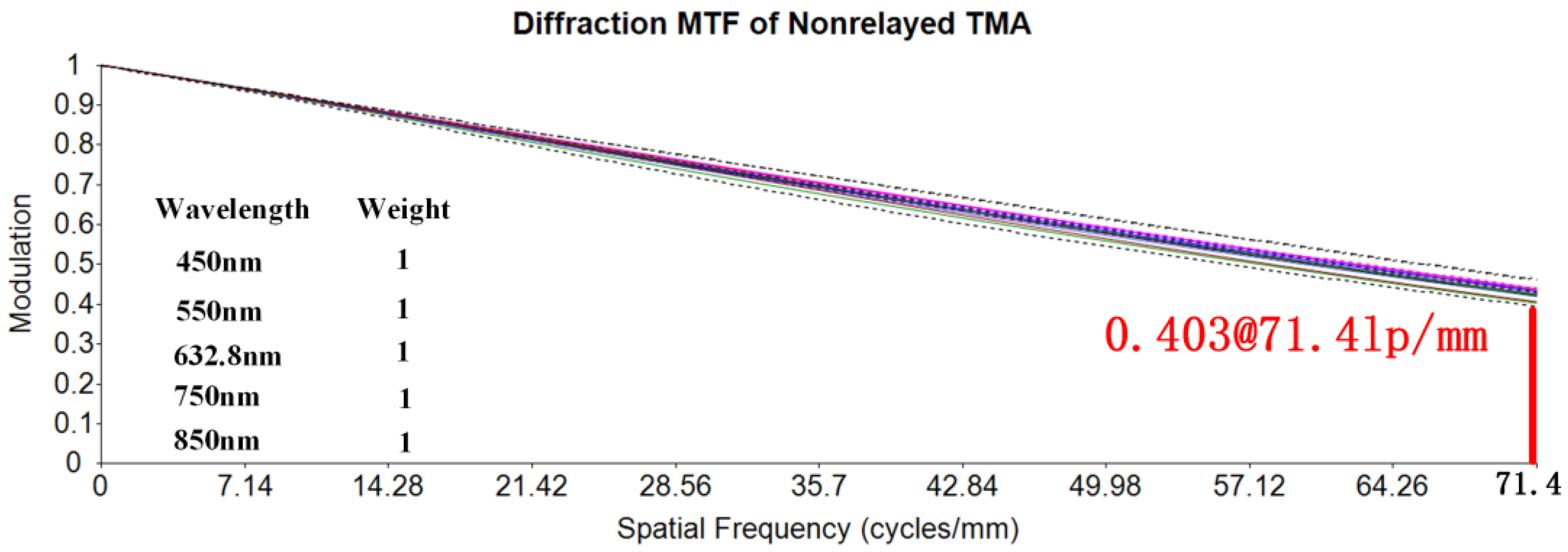
| 5 | Nyquist frequency (lp/mm) | 71.4 |
| Mirror | Surface Type | Radius (mm) | Distance (mm) | Conic | Size (mm) |
|---|---|---|---|---|---|
| PM | X–Y polynomial | −1538.978 | −384.8 | −1.52 | 444 × 125 |
| SM | Paraboloid | −592.75 | 384.8 | −1 | Φ58 |
| TM | Even asphere | −935.58 | −648.81 | −0.178 | 392 × 84 |
| No. | Item | Aij | No. | Item | Aij | No. | Item | Aij |
|---|---|---|---|---|---|---|---|---|
| 1 | X1Y0 | 0 | 10 | X4Y0 | 2.09 × 10⁻¹¹ | 19 | X1Y4 | 0 |
| 2 | X0Y1 | −3.97 × 10⁻⁴ | 11 | X3Y1 | 0 | 20 | X0Y5 | −1.63 × 10⁻¹³ |
| 3 | X2Y0 | −1.41 × 10⁻⁷ | 12 | X2Y2 | 3.8 × 10⁻¹¹ | 21 | X6Y0 | −2.98 × 10⁻¹⁷ |
| 4 | X1Y1 | 0 | 13 | X1Y3 | 0 | 22 | X5Y1 | 0 |
| 5 | X0Y2 | −1.37 × 10⁻⁷ | 14 | X0Y4 | 4.47 × 10⁻¹¹ | 23 | X4Y2 | −7.32 × 10⁻¹⁸ |
| 6 | X3Y0 | 0 | 15 | X5Y0 | 0 | 24 | X3Y3 | 0 |
| 7 | X2Y1 | 7 × 10⁻¹⁰ | 16 | X4Y1 | −2.01 × 10⁻¹⁴ | 25 | X2Y4 | 6.83 × 10⁻¹⁸ |
| 8 | X1Y2 | 0 | 17 | X3Y2 | 0 | 26 | X1Y5 | 0 |
| 9 | X0Y3 | −1.39 × 10⁻⁹ | 18 | X2Y3 | −2.63 × 10⁻¹⁴ | 27 | X0Y6 | 3.4 × 10⁻¹⁶ |
| No. | x/(°) | y/(°) | No. | x/(°) | y/(°) |
|---|---|---|---|---|---|
| 1 | 0 | −5 | 6 | 8.05 | −5.5 |
| 2 | 5.75 | −5 | 7 | 11.5 | −5.5 |
| 3 | 8.05 | −5 | 8 | −5.75 | −6 |
| 4 | 11.5 | −5 | 9 | −8.05 | −6 |
| 5 | 5.75 | −5.5 | 10 | −11.5 | −6 |
| Type | Item | Primary Mirror | Secondary Mirror | Tertiary Mirror |
|---|---|---|---|---|
| Displacement x/mm | - | 0.05 | 0.1 | |
| Displacement y/mm | - | 0.05 | 0.1 | |
| Assembling | Displacement z/mm | - | 0.2 | 0.3 |
| Tilt α/(″) | - | 20 | 20 | |
| Tilt β/(″) | - | 20 | 30 | |
| Tilt γ/(″) | - | 40 | 60 | |
| ΔR/mm | 0.8 | 0.3 | 0.3 | |
| Manufacturing | ΔK | 0.001 | 0.002 | 0.001 |
| Surface error RMS (λ = 632.8 nm) | λ/50 | λ/50 | λ/50 |
Disclaimer/Publisher’s Note: The statements, opinions and data contained in all publications are solely those of the individual author(s) and contributor(s) and not of MDPI and/or the editor(s). MDPI and/or the editor(s) disclaim responsibility for any injury to people or property resulting from any ideas, methods, instructions or products referred to in the content. |
© 2023 by the authors. Licensee MDPI, Basel, Switzerland. This article is an open access article distributed under the terms and conditions of the Creative Commons Attribution (CC BY) license (https://creativecommons.org/licenses/by/4.0/).
Share and Cite
Jia, B.; Li, Y.; Lv, Q.; Jin, F.; Tian, C. Design of a Large Field of View and Low-Distortion Off-Axis Optical System Based on a Free-Form Surface. Photonics 2023, 10, 506. https://doi.org/10.3390/photonics10050506
Jia B, Li Y, Lv Q, Jin F, Tian C. Design of a Large Field of View and Low-Distortion Off-Axis Optical System Based on a Free-Form Surface. Photonics. 2023; 10(5):506. https://doi.org/10.3390/photonics10050506
Chicago/Turabian StyleJia, Bing, Yubing Li, Qiongying Lv, Fan Jin, and Chunlin Tian. 2023. "Design of a Large Field of View and Low-Distortion Off-Axis Optical System Based on a Free-Form Surface" Photonics 10, no. 5: 506. https://doi.org/10.3390/photonics10050506