Communication

Intensity Modulation of Two Weakly Coupled Stimulated Oscillating Mechanical Modes in an Optomechanical Microbubble Resonator

1
Key Lab for Micro and Nanophotonic Structures (Ministry of Education, China), Department of Optical Science and Engineering, School of Information Science and Engineering, Fudan University, Shanghai 200433, China
2
Department of Physics, Fudan University, Shanghai 200433, China
*
Authors to whom correspondence should be addressed.
Photonics 2023, 10(4), 365; https://doi.org/10.3390/photonics10040365
Submission received: 9 March 2023 / Revised: 21 March 2023 / Accepted: 22 March 2023 / Published: 24 March 2023
(This article belongs to the Special Issue Micro-Nano Optical Devices)

Abstract

:
We report that when two stimulating mechanical modes in an optomechanical microbubble resonator are weakly coupled to each other, strong oscillation intensity modulation occurs. The modulation was theoretically expected and experimentally observed. We theoretically derived the expressions of the coupling coefficient between the mechanical modes and calculated the region where weak coupling happens. We found that weak coupling exists when the optical quality factor of the microcavity is high and the detuning of the pump laser is close to the beat frequency of the two mechanical modes. Experimentally, we observed that when two mechanical modes are both in stimulated oscillation, they undergo strong intensity modulation as the optical pump power changes, and the coupling coefficient of the two modes is estimated to be 0.962 at the pump power when one mode is in the stimulated region and the other mode is at a stimulating threshold; this proves that the two mechanical modes are weakly coupled. Our results extended the weak coupling conclusion in multimode laser emission to stimulated oscillation in multiple mechanical modes.

1. Introduction

Cavity optomechanics describes the coupling behavior between the optical resonators and the mechanical resonators within an optical cavity [1]. The optically induced mechanical damping rate can be positive (leads to mechanical cooling) or negative (leads to mechanical amplification), depending on whether the pump laser is red-detuned or blue-detuned to the optical resonance [2,3]. Once the overall damping rate of the mechanical mode is negative in the blue-detuned regime, self-sustained oscillation of the mechanical mode occurs. This is also known as mechanical lasing or phonon lasing [4]. Single-mechanical-mode lasing has been extensively explored in whispering-gallery-mode (WGM) and Fabry–Perot (F–P) microcavities [5,6,7,8,9,10,11,12]. Optomechanical coupling efficiency can be high because the optical resonator has a high quality factor (Q) and a small mode volume [13]. On the other hand, multimode phonon lasing can serve as a new research method for the exploration of physical phenomena such as self-organized synchronization [14,15,16,17] and acoustic frequency combs [18]. However, there are much fewer references on multimode phonon lasing. In fact, optical resonance in the cavity can couple with multiple mechanical modes simultaneously. However, only one mechanical mode can reach the threshold condition of stimulated oscillation because of the mechanical mode competition [18,19,20]. Additional controls are necessary to achieve simultaneous multiple mechanical mode lasing in an optomechanical system, which includes adding multiple mechanical vibration structures into the system [15,16], using multiple beat frequencies generated between multiple incident lasers to resonate with multiple mechanical modes [21], or using mode-locking techniques [18].
In the field of optical lasers, multiple longitudinal mode lasing techniques have been investigated. In 1964, Lamb found that, theoretically, when two lasing modes are in the strong coupling regime, mode competition leads to single-mode lasing. On the other hand, when two lasing modes are in the weak coupling regime, multimode lasing is allowed [22]. Mode competition effects have also been observed in Raman lasers, and single-mode switching or dual-mode Raman lasing can be achieved with the suitable system parameters [23,24]. Therefore, studying the analogous issue in an optomechanical system and investigating the relation of multiple mechanical modes lasing with the coupling strength would be interesting and important.
In this paper, we first derived the expressions of mode-coupling coefficients whereby an optical resonant mode is coupled to two mechanical modes. The simulation results revealed that dual-mode lasing exists when two mechanical modes couple weakly. Experimentally, we observed dual-mechanical-mode lasing in a microbubble optical resonator. As theory predicts, the intensities of the two lasing modes modulate when the optical pump intensity changes. We also confirmed from the experimental results that the system is truly in a weak coupling condition. This work, while further demonstrating the analogy of optomechanical phonon lasers to optical lasers, also helps to simplify the design of the optomechanical systems that facilitate the simultaneous stable lasing of multiple mechanical modes and provides guidance for future research into optomechanical acoustic frequency combs.

2. Two Mechanical Modes Coupling Theory in Optomechanical System

If we consider an optomechanical system in which a high-Q optical resonant mode couples with two mechanical modes in whispering-gallery-mode microcavity (in our case it is a microbubble resonator, MBR [25,26]), the oscillation modulation can be understood as follows. The change in the amplitude of one mechanical mode will lead to a change in the optical resonance frequency. Then, the amplitude of the intracavity optical field changes, which in turn will change the optically induced damping rate of both the mechanical modes.
To theoretically manage the coupling of the mechanical modes in an MBR, we follow the framework in which one optical mode couples with multiple mechanical modes in the (WGM/F–P) microcavity proposed in Ref. [13] and with the solution process of the F-P cavity system shown in Ref. [19].
The circulating optical field in an MBR with radius R is denoted by a t , it exerts circulating radiation pressure F R P t = a t 2 / R on the cavity boundary, and the equation is as follows [5,13]:
d a t d t = i Δ x a t κ 2 a t + 1 τ e x s t ,     Δ x = Δ + ω 0 R x t ,
In which the optical field loss rate is κ 2 = 1 2 τ 0 + 1 2 τ e x , where 1 τ 0 describes the intrinsic cavity loss rate, and 1 τ e x describes the loss rate of the optical field when it couples to an MBR optical mode from a tapered fiber. s t 2 is the pump laser power, and the detuning Δ is the angular frequency difference between the pump laser and the optical resonance (i.e., Δ = ω ω 0 ). x t is the time-dependent change in the MBR radius.
When two mechanical modes A and B are coupled to one optical resonant mode simultaneously, x t can be expressed as follows [13]:
x t = n c n t ϕ n
where n = A or B, c n t = c n s i n Ω n t is the one-dimensional equivalent amplitude of the three-dimensional mechanical mode distribution, ϕ n is a number in the range of 0–1 that determines the relative transduction strength of c n t in x t [13], and Ω n is the mechanical mode frequency. Thus, Equation (1) can be written as follows:
d a t d t = i Δ + ω 0 R n c n t ϕ n κ 2 · a t + 1 τ e x s t
Meanwhile, c n t follows the motional equation [13]:
c ¨ n t + Γ n i n t r + Γ n R P c ˙ n t + Ω n 2 c n t = F t h t m e f f n
where m e f f n is the effective mass of the mechanical mode, F t h t is the thermal Langevin force, and Γ n i n t r is the mechanical damping rate of the mode. Γ n R P is the optically induced damping rate of the mechanical mode, which is determined by the effective radiation pressure F n t = F R P t ϕ n [13,19].
After obtaining a t with Equation (3), we can further identify F n t , and then obtain Γ n R P as follows [19]:
Γ A R P χ A , χ B = 2 ϕ A 2 τ e x R 2 ω 0 s 2 Ω A 2 m e f f A I m 1 χ A k , l = J k χ A J k 1 χ A κ 2 i Δ k Ω A + l Ω B J l 2 χ B κ 2 + i Δ k 1 Ω A + l Ω B
Γ B R P χ A , χ B = 2 ϕ B 2 τ e x R 2 ω 0 s 2 Ω B 2 m e f f B I m 1 χ B k , l = J k χ B J k 1 χ B κ 2 i Δ k Ω B + l Ω A J l 2 χ A κ 2 + i Δ k 1 Ω B + l Ω A
where χ n = c n R ω 0 Ω n Δ ϕ n are the dimensionless parameters used to describe the mechanical mode amplitude c n more concisely. Equations (5) and (6) are more or less similar to that in Ref. [19], which was derived for determining the F–P cavity. However, the expression before the imaginary part is for the whispering-gallery-mode cavity. The two equations clearly show that the damping rate of mode A and B comes from the behavior of both modes, i.e., there is coupling between the two mechanical modes. It should be noted that the coupling between the mechanical modes is not direct but occurs through the optical mode.
To describe the coupling strength between the mechanical modes in the optomechanical system, we follow the procedure of multimode optical lasing, and derive the change of the gain coefficients of the two modes as follows [22]:
Δ G 1 = β 1 Δ E 1 2 θ 12 Δ E 2 2
Δ G 2 = β 2 Δ E 2 2 θ 21 Δ E 1 2
where E n 2 describes the intensity of the mechanical mode, β n is the self-saturation coefficient, and θ 12 and θ 21 are cross-saturation coefficients. The cross-saturation coefficients reflect how much one mode is suppressed by the other mode. In optical laser technology, the coupling coefficient C is used to identify the coupling state of the two modes [22]:
C = θ 12 θ 21 β 1 β 2
The larger the value of C, the stronger the coupling between the two modes will be. C > 1 is the strong coupling region, where the cross-saturation between the two mechanical modes is stronger than the self-saturation effect, and the competition between two modes is so strong that only one mode involves stable lasing. C < 1 is the weak coupling region, where the cross-saturation between the two mechanical modes is weaker than the self-saturation, and the two-modes competition allows both modes to establish stable lasing [22]. According to Equation (4), the gain of the nth mode can be written as: G n = Γ n i n t r Γ n R P c A , c B , s 2 , where Γ n i n t r is fixed. So, the total derivative of G n is:
Δ G A = Δ Γ A R P c A , c B , s 2 = Γ A R P c A · Δ c A Γ A R P c B · Δ c B Γ A R P s 2 · Δ s 2
Δ G B = Δ Γ B R P c A , c B , s 2 = Γ B R P c B · Δ c B Γ B R P c A · Δ c A Γ B R P s 2 · Δ s 2
When the pump power is fixed, Equations (10) and (11) can be simplified as:
Δ G A = Δ Γ A R P c A , c B = Γ A R P c A · Δ c A Γ A R P c B · Δ c B
Δ G B = Δ Γ B R P c A , c B = Γ B R P c B · Δ c B Γ B R P c A · Δ c A
By comparing the above equations with Equations (7) and (8), self-saturation coefficients β 1 and β 2 can be derived from Γ A R P c A and Γ B R P c B , and the cross-saturation coefficients θ 12 and θ 21   can be derived from Γ A R P c B and Γ B R P c A . According to Equation (9), the coupling coefficient between the mechanical modes is:
C = Γ A R P c B · Γ B R P c A Γ A R P c A · Γ B R P c B  
In an MBR optomechanical system where two mechanical modes oscillate simultaneously, when the optically induced gain of both mechanical modes exceeds their intrinsic loss, the subsequent evolution of these modes will depend on the strength of their coupling. In this process, due to the optical mode and mechanical modes having been determined, the parameters ϕ n , Ω n , m e f f n in Equations (5) and (6) will be fixed. Combining Equations (5), (6) and (14), it can be noted that, for an MBR optomechanical system with dual-mode oscillation, the parameters affecting the C are mainly the optical mode Q value, the pump laser detuning Δ , and χ n . χ n is determined by both the pump laser power s 2 and Γ n i n t r .
Here, we provide the simulation results. Consider an MBR optomechanical system that has a radius of cavity R = 145.0   μ m , ω 0 = 1.215 × 10 15   Hz , Q = 8.1 × 10 7 , κ / 2 π = 2.38   MHz , τ e x = 70   ns , Ω A / 2 π = 6.03   MHz , and Ω B / 2 π = 9.15   MHz , with the radial/axial/angular quantum numbers for the two mechanical modes being 1/2/1 and 1/3/3, respectively. The intrinsic damping rate of the two mechanical modes is taken as Γ A i n t r / 2 π = 1.60 × 10 4   s 1 and Γ B i n t r / 2 π = 1.66 × 10 4   s 1 , values which are similar to some WGM optomechanical systems observed so far ( Γ m e c h i n t r / 2 π = 2.0 × 10 4   s 1 [27]; Γ m e c h i n t r / 2 π = 1.2 × 10 4   s 1 [28]). The effective mass of the two mechanical modes is calculated by performing finite element simulation as m e f f A = 7.03 × 10 9   kg , and m e f f B = 2.28 × 10 9   kg . In addition, assume ϕ A   = 0.15 , and ϕ B   = 0.18 , such that the pump power range where mode intensity modulation occurs is similar to that in the experiment. The ratio of detuning to the optical field loss rate is 0.8 (i.e., Δ / κ = 0.8 ).
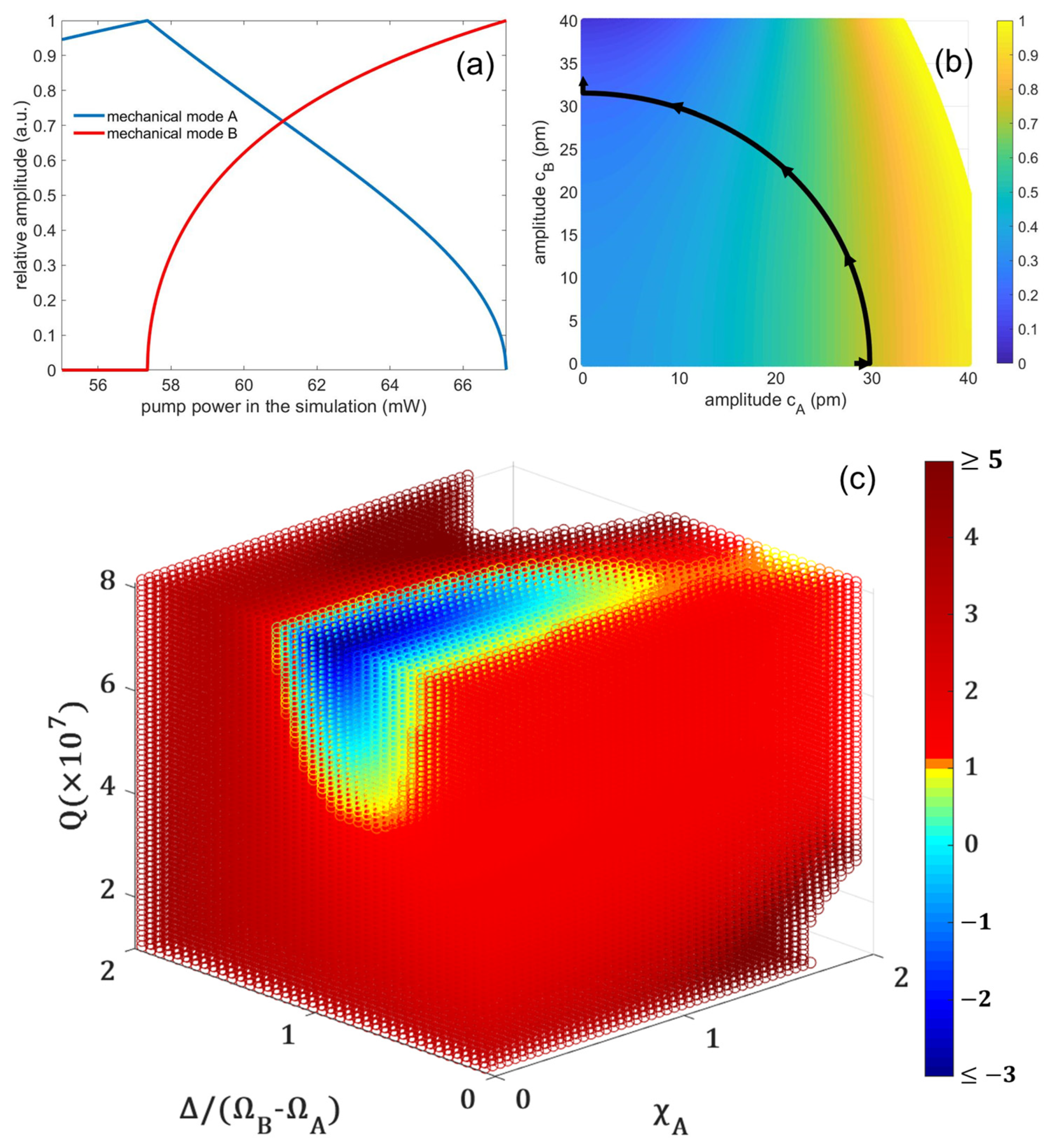
Figure 1a plots the change in mechanical mode intensity as a function of optical power in the cavity, which is calculated by Equations (4)–(6). As s 2 increases from 55.00 mW to 67.18 mW, the intensity of the two mechanical modes will change oppositely in response to the change in pump power. This is because when the intensity of mechanical mode B increases, it depletes more energy from the intracavity optical field, leaving less energy for mechanical mode A and resulting in a decrease in its intensity. Figure 1b plots the weak coupling region according to Equation (14) and marks the intensity changes of the two mechanical modes in the above simulation results with black curves. As the intensity changes, the coupling coefficient decreases. This is because when the mechanical mode B is also lased, the amplitude of the mechanical mode B changes more significantly within one cycle, causing the corresponding intracavity intensity variation to be more severe. This results in the optically induced damping rate of the mechanical mode B being more affected by its amplitude changes compared to when it is not lased. As a result, the coupling coefficient decreases. Therefore, the highest coupling coefficient is reached at the point when one mode is in lasing and the second mode is at the lasing threshold; when the highest coupling coefficient is still less than 1, it will be able to observe two weakly coupled stimulated oscillating mechanical modes with increased s 2 . To determine the weak coupling region that supports these two modes of stimulated oscillating, the relationship between the highest coupling coefficient value and the parameters must be studied. In this process, the amplitude of the second mechanical mode can be disregarded as it is not yet in lasing.
Figure 1c plots the coupling coefficient as a function of the optical mode Q value, the detuning D, and the dimensionless amplitude χ A , which are calculated by Equations (5), (6) and (14). χ A varies from 0 to 2, Q ranges from 1.0 × 10 7 to 8.1 × 10 7 , and D is between 0–2 of Ω B Ω A . The other parameters are the same as those used in previous calculations. As shown in Figure 1c, C is comparatively lower when Δ ≈ Ω B Ω A . This is due to the high-frequency sidebands generated by the modulation of the pump laser by the oscillation of mechanical mode A, which exerts a relatively stronger gain on mechanical mode B. This ultimately causes the numerator in Equation (14) to decrease or become negative. In addition, when Q is higher, C is less. This is because the higher the Q factor is, the narrower the optical mode, and the more significant the intracavity intensity variation caused by the cavity boundary oscillation will be, causing Γ n R P to be more severely affected by the changes brought by c n and resulting in an increase in the denominator of Equation (14).

3. Experiment

Figure 2 illustrates the experiment setup. The optomechanical resonator is a hollow microbubble resonator (MBR) with a radius of 145.0   μ m and a thickness of 12.5   μ m . The MBR is fabricated by using a silica capillary (Polymicro TSP 075150, Polymicro Technologies, Phoenix, AZ, USA) with an outer diameter of 150   μ m and an inner diameter of 75   μ m . After removing its protective layer on the outer surface, we followed the method outlined in Ref. [29] to form the microbubble cavity. To integrate the pump laser into the MBR, we fixed it on a three-dimensional translation stage and align it orthogonally with a fused tapered fiber under a microscope. The pump laser (near 1551 nm) output from a tunable laser (CTL1550, TOPTICA Photonics AG) is coupled into the MBR through a fused tapered fiber after of the integration of a polarization controller (FPC031, Thorlabs, Inc., Newton, NJ, USA), an electro-optic modulator (EOM) (LN53S, Thorlabs) and an erbium-doped fiber amplifier (EDFA) (GA3223, CONNET). The transmitted light is received by a photodetector and then split by a BNC cable and connected to the oscilloscope (TDS3032, Tektronix, Beaverton, OR, USA) and the spectrometer (RSA306B, Tektronix), respectively. In front of the microbubble resonator, the A 1/99 fiber coupler splits 1% of the output to a power meter (AQ2140, Ando Electric Co., Ltd., Kamata, Tokyo).

4. Results and Discussion

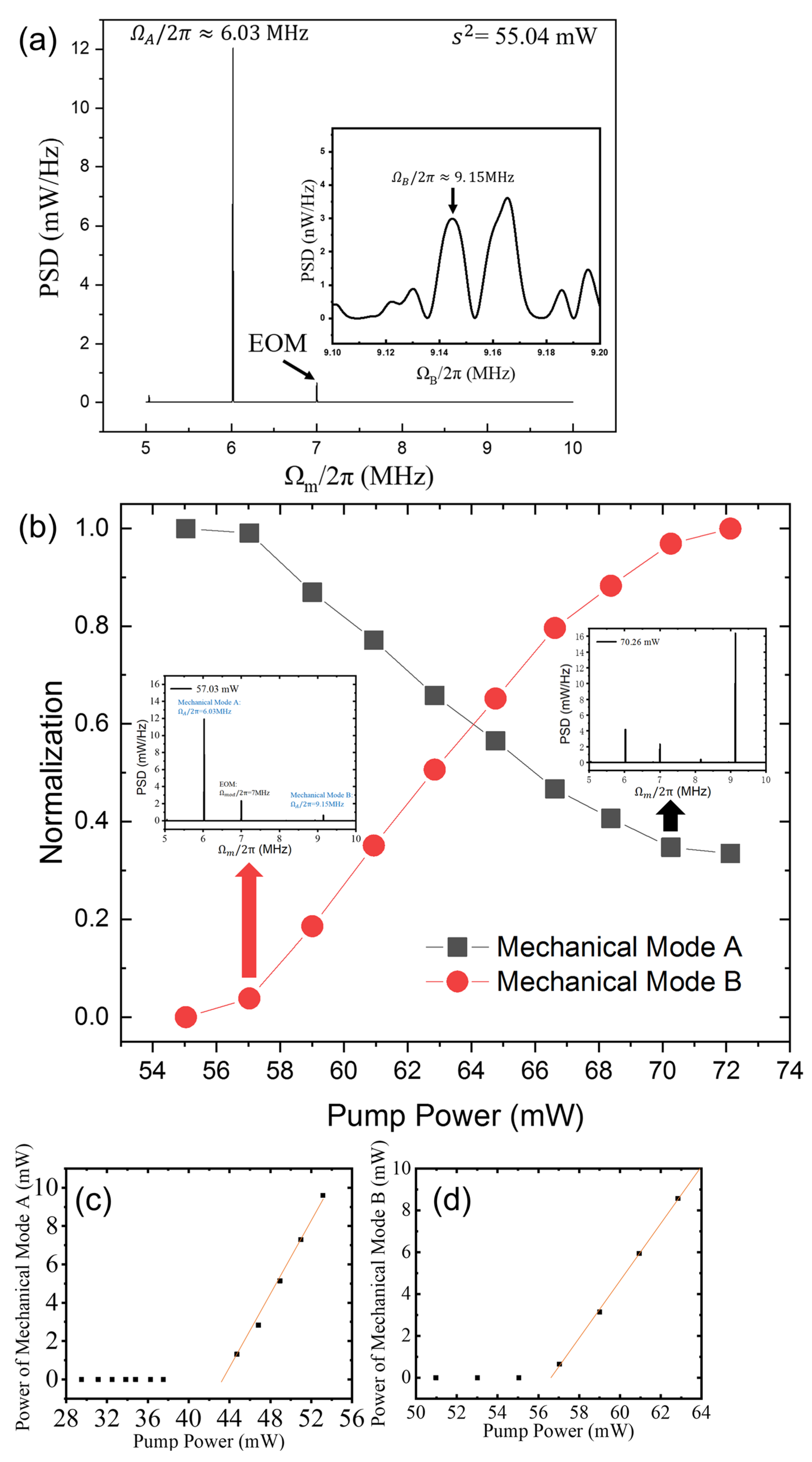
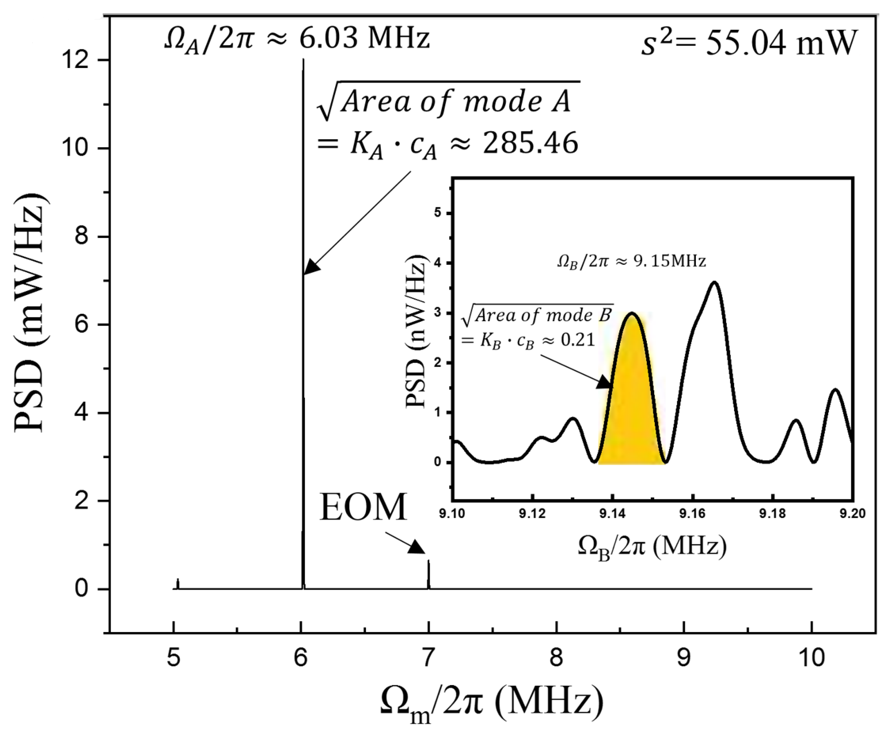
Figure 3a plots a spectrum in a range of 5 to 10 MHz. When the tunable laser wavelength is fixed to an optical mode with a Q = 8.1 × 10 7 , the pump laser power is s 2 = 55.04   mW .   Mechanical mode A at Ω A / 2 π = 6.03   MHz and the modulation frequency of the EOM at 7 MHz are observed. Figure 3b plots the changes in mechanical mode intensity when pump laser power increases from 55.04 mW to 72.13 mW. A second mechanical mode, mode B at Ω B / 2 π = 9.15   MHz , can be observed clearly at a laser power of 57.03 mW, and its intensity rises continuously. Meanwhile, the intensity of mode A drops to about 30% when the laser pump reaches 72.13 mW. Figure 3c,d plot the variation of the intensity of mechanical modes A and B at different pump powers, respectively. The stimulated oscillation thresholds of modes A and B are 43.69 mW and 56.57 mW, respectively.
The experimental results show that when the pump power is above 56.57 mW, both mode A and B lase. Their lasing intensities change in opposite ways when pump power increases further. This modulation of the oscillation intensity is analogous to the modulation of laser intensity of two weakly coupled laser modes in a Zeeman laser [30], in which the intensity of the two laser modes changes oppositely.
As mentioned above, the coupling coefficient C is the highest when mode A is lasing and mode B is at lasing threshold ( i . e . ,   c A = c A , c B 0 ). If C < 1 at this state, the coupling will be weaker when the pump laser power is higher. The detailed coupling coefficient estimation process is provided in the Appendix A, using Equations (10), (11) and (14) and experimental data.
Finally, the coupling coefficient C can be obtained as follows:
C = Γ A R P c B · Γ B R P c A Γ A R P c A · Γ B R P c B 0.962
In this calculation, the power spectral density area measurement for mechanical mode B that does not satisfy the threshold condition is assumed to have a ±15% error (corresponding to an error of −7.8% to +7.2% of K n · c n ), and a ±0.8% error is assumed regarding the measurement of the pump laser power when mechanical mode B is about to lase (corresponding to an upper limit of power error exactly close to 57.03 mW). As such, we are able to obtain the error range of C in (0.561, 0.997). Therefore, the state of mechanical mode B when it is about to lase ( c A = c A , c B 0 ) is exactly in the weak coupling region.

5. Conclusions

In conclusion, we demonstrated that, in a optomechanical system, two mechanical modes can be simultaneously stimulated in situations when they are weakly coupled. Consequently, the intensity of the two modes changes oppositely when pump power increases. We theoretically derived the interaction between the two modes and experimentally found the modulation of the intensity of the two mechanical modes, and the coupling coefficient was estimated to be 0.962. This research will make it easier to design an optomechanical system that supports the simultaneous stable lasing of multiple mechanical modes. In the future, it may be possible to use it to help with studying acoustic frequency combs.

Author Contributions

Conceptualization, X.Y., L.X. and L.L.; Investigation, X.Y.; Methodology, X.Y., L.X. and L.L.; Resources, L.X. and L.L.; Validation, X.Y. and L.X.; Visualization, X.Y.; Writing—original draft, X.Y.; Writing—review & editing, X.Y. and L.X. All authors have read and agreed to the published version of the manuscript.

Funding

This research was funded by National Natural Science Foundation of China (NSFC) (11874122, 11474070, 61327008 and 11074051) and Doctoral Program of Higher Education (20130071130004).

Institutional Review Board Statement

Not applicable.

Informed Consent Statement

Not applicable.

Data Availability Statement

The datasets used and/or analyzed during the current study are available from the corresponding author upon reasonable request.

Conflicts of Interest

The authors declare no conflict of interest.

Appendix A

In this section, we estimate the coupling coefficient C of mode A and B, when mode A is lasing and mode B is at the lasing threshold. C is following Equation (14) in the main text.
C = Γ A R P c B · Γ B R P c A Γ A R P c A · Γ B R P c B  
However, the lasing threshold of mode B (56.57 mW) was extrapolated from experimental data. Therefore, we need to use experimental data close to 56.57 mW to estimate C.
It is worth mentioning that the parameter c n cannot be directly measured in the experiment. So, we deal with the parameter c n in this way: the arithmetic square root of the mechanical mode power spectral density area is proportional to the mechanical mode amplitude c n [11], which we denote as K n · c n , as shown in Figure A1. This can be considered a dimensionless quantity and there is no need to measure the scaling factor K n because K n will be simplified in Equation (A1).
Figure A1. Power spectrum of transmitted light ( s 2 = 55.04 mW) obtained by the spectrometer, with K A · c A marked. Insert: Power spectrum at mechanical mode B after enlarging the vertical coordinate, with K B · c B marked.
Photonics 10 00365 g0a1
There are 3 experimental points around 56.57 mW, they are summarized in Table A1.
Table A1. Arithmetic square root of the generalized integral of the power spectrum for mechanical modes A and B at different pumping powers.
Pump Power53.02 mW55.04 mW57.03 mW
Mechanical mode A255.09285.46284.15
Mechanical mode B0.150.2166.26
In the following section, we detail the calculation process of the 4 derivates in Equation (A1) and eventually obtain C.
Part 1. Γ A R P c A , the self-saturation coefficient of mechanical mode A.
Equation (10) in the main text indicates that
Γ A R P c A = Δ Γ A R P Γ A R P c B · Δ c B Γ A R P s 2 · Δ s 2 Δ c A  
We use the data before mode B lases (pump power s 2 = 53.02 mW and 55.04 mW) to calculate Γ A R P c A and assume Γ A R P c A maintains at s 2 = 56.57 mW, since mode A is continuous in lasing and pump power increases very little. When only mode A stably lases, Δ c B 0 and Δ Γ A R P = 0 . According to Equations (5) and (6) of the main text, we have
Γ A R P s 2 = Γ A R P c A , c B , s 2 s 2 = Γ A i n t r s 2  
Γ A i n t r / 2 π = 1.60 × 10 4   s 1 can be obtained from the analysis of experimental data. Thus, we have:
Γ A R P c A = Δ Γ A R P Γ A R P c B · Δ c B + Γ A i n t r s 2 · Δ s 2 Δ c A = 1.60 × 10 4 × 55.04 53.02 53.02 × 285.46 255.09 20.07   s 1
Part 2. Γ A R P c B , the cross-saturation coefficient of mechanical mode A.
From Equation (10) in the main text, we have
Γ A R P c B = Δ Γ A R P Γ A R P s 2 · Δ s 2 Γ A R P c A · Δ c A Δ c B  
We use data equal to and larger than the lasing threshold of mode B ( s 2 = 56.57 mW and 57.03 mW) together with Γ A R P c A , previously obtained in part one, to calculate Γ A R P c B , and assume Γ A R P c B is the same at s2 = 56.57 mW. Since mode A keeps lasing, we have Δ Γ A R P = 0 and Γ A R P s 2 = Γ A i n t r s 2 . Consider that Δ c B 0 when s 2 < 56.57   mW , Δ c B can directly be calculated from the c B at s 2 = 55.04   mW   and   57.03   mW ( Δ c B 66.26 0.21 = 66.05 ). On the other hand, c A at s 2 = 56.57   mW   needed to be calculated. From Equation (10) in the main text, we obtain
K A · Δ c A = Γ A R P s 2 · Δ s 2 Γ A R P c A  
take Γ A R P c A already calculated in part one, K A · Δ c A under s 2 = 55.04   mW 56.57   mW is
K A · Δ c A 55.04   mW 56.57   mW = 1.60 × 10 4 55.04 · 56.57 55.04 20.07 22.16
Therefore,
K A c A 56.57   mW = K A c A 55.04   mW + K A · Δ c A 55.04   mW 56.57   mW = 307.62
K A · Δ c A   56.57   mW 57.03   mW = 23.47
With that, we obtain
Γ A R P c B = Δ Γ A R P Γ A R P s 2 · Δ s 2 Γ A R P c A · Δ c A Δ c B                                                                                                                                                                                                                                         = 1.60 × 10 4 × 57.03 56.57 56.57 20.07 × 284.15 285.46 22.16 66.26 0.21 9.10   s 1
Part 3. Γ B R P c A , the cross-saturation coefficient of mode B.
According to Equation (11) of the main text,
Δ G B = Δ Γ B R P c A , c B , s 2 = Γ B R P c B · Δ c B Γ B R P c A · Δ c A Γ B R P s 2 · Δ s 2
consider Δ c B 0 when s 2 < 56.57 mW, Equation (A5) can be simplified to
Δ Γ B R P c A , c B , s 2 = Γ B R P c A · Δ c A Γ B R P s 2 · Δ s 2
Δ Γ B R P c A , c B , s 2 and Γ B R P s 2 need to be calculated to obtain Γ B R P c A .
Δ Γ B R P can be obtained from [1,4,19]:
c B 2 ~ Γ B i n t r Γ B i n t r + Γ B R P
Take c B ( s 2 = 53.02   mW )/ c B ( s 2 = 55.04   mW ) = 0.21/0.15, we have:
0.21 2 0.15 2 = Γ B i n t r + Γ B R P s 2 = 53.02   mW Γ B i n t r + Γ B R P s 2 = 55.04   mW = 1 1 + Δ Γ B R P s 2 = 53.02   mW 55.04   mW Γ B i n t r + Γ B R P s 2 = 53.02   mW
In which
Δ Γ B R P s 2 = 53.02   mW 55.04   mW = Γ B R P s 2 = 55.04   mW Γ B R P s 2 = 53.02   mW
Meanwhile, using the lasing threshold at s 2 = 56.57 mW, Γ B i n t r + Γ B R P s 2 = 56.57   mW = 0 , and
Γ B R P s 2 = 56.57   mW                                                                                                                                                                                                                                                                         = Γ B R P s 2 = 53.02   mW + Δ Γ B R P s 2 = 53.02   mW 55.04   mW                                                                                                                                                                                     + Δ Γ B R P s 2 = 55.04   mW 56.57   mW .
We obtain
Γ B i n t r + Γ B R P s 2 = 53.02   mW Δ Γ B R P s 2 = 53.02   mW 55.04   mW + 1 + Δ Γ B R P s 2 = 55.04   mW 56.57   mW Δ Γ B R P s 2 = 53.02   mW 55.04   mW = 0
Substitute Equation (A8) into the above equation to obtain
Δ Γ B R P s 2 = 53.02   mW 55.04   mW Δ Γ B R P s 2 = 55.04   mW 56.57   mW 0.96
Next, combine the above equation with Equation (A6) to obtain
Δ Γ B R P s 2 = 53.02   mW 55.04   mW Δ Γ B R P s 2 = 55.04   mW 56.57   mW = 0.96 = Γ B R P c A · 285.46 255.09 Γ B R P s 2 · 55.04 53.02 Γ B R P c A · 22.16 Γ B R P s 2 · 56.57 55.04
From the above equation, we obtain
Γ B R P / c A / Γ B R P / s 2 0.06
Note that Γ B R P / s 2 = Γ B i n t r / s 2 at s 2 = 56.57 mW; using Γ B i n t r / 2 π = 1.66 × 10 4   s 1 , we obtain
Γ B R P c A = Γ B R P / c A Γ B R P / s 2 · Γ B i n t r s 2 = 1.66 × 10 4 56.57 × 0.06 17.61   s 1
Part 4. Γ B R P c B , the self-saturation coefficient of mode B
From Equation (A5) we have
Γ B R P c B = Δ Γ B R P Γ B R P s 2 · Δ s 2 Γ B R P c A · Δ c A Δ c B
We use data for both mode A and B lasing (i.e., s 2 = 56.57 mW 57.03 mW) together with Γ B R P c A previously obtained in part 3 to obtain Γ B R P c B , and assume it is equal to Γ B R P c B at s 2 = 56.57 mW. When s 2 > 56.57 mW, Δ G B = Δ Γ B R P = 0 and Γ B R P s 2 = Γ B i n t r s 2 . K A · Δ c A and K B · Δ c B can be obtained as in the previous calculation of Γ A R P c B . With that, we have
Γ B R P c B = Δ Γ B R P Γ B R P s 2 · Δ s 2 Γ B R P c A · Δ c A Δ c B                                                                                                                                                                                                                         = 1.66 × 10 4 × 57.03 56.57 56.57 Γ B R P c A × 284.15 285.46 22.16 66.26 0.21 8.3   s 1 .
Finally, the coupling coefficient C is as follows:
C = Γ A R P c B · Γ B R P c A Γ A R P c A · Γ B R P c B 0.962

References

  1. Kippenberg, T.J.; Vahala, K.J. Cavity Opto-Mechanics. Opt. Express 2007, 15, 17172–17205. [Google Scholar] [CrossRef] [PubMed]
  2. Braginsky, V.B.; Manukin, A.; Tikhonov, M.Y. Investigation of Dissipative Ponderomotive Effects of Electromagnetic Radiation. Sov. Phys. JETP-USSR 1970, 31, 829–834. [Google Scholar]
  3. Braginsky, V.B.; Strigin, S.; Vyatchanin, S.P. Parametric oscillatory instability in Fabry-Perot interferometer. Phys. Lett. A 2001, 287, 331–338. [Google Scholar] [CrossRef]
  4. Aspelmeyer, M.; Kippenberg, T.; Marquardt, F. Cavity optomechanics. Rev. Mod. Phys. 2014, 4, 1391–1452. [Google Scholar] [CrossRef]
  5. Rokhsari, H.; Yang, L.; Kippenberg, T.J.; Vahala, K.; Carmon, T. Temporal Behavior of Radiation-Pressure-Induced Vibrations of an Optical Microcavity Phonon Mode. Phys. Rev. Lett. 2005, 94, 223902. [Google Scholar] [CrossRef]
  6. Rokhsari, H.; Kippenberg, T.J.; Carmon, T.; Vahala, K.J. Radiation-pressure-driven micro-mechanical oscillator. Opt. Express 2005, 13, 5293–5301. [Google Scholar] [CrossRef]
  7. Cross, M.C.; Vahala, K.; Carmon, T. Chaotic Quivering of Micron-Scaled On-Chip Resonators Excited by Centrifugal Optical Pressure. Phys. Rev. Lett. 2007, 98, 167203. [Google Scholar] [CrossRef]
  8. Grudinin, I.S.; Lee, H.; Painter, O.; Vahala, K.J. Phonon Laser Action in a Tunable Two-Level System. Phys. Rev. Lett. 2010, 104, 0839018. [Google Scholar] [CrossRef]
  9. Khurgin, J.B.; Pruessner, M.W.; Stievater, T.; Rabinovich, W.S. Laser-Rate-Equation Description of Optomechanical Oscillators. Phys. Rev. Lett. 2012, 108, 22390422. [Google Scholar] [CrossRef]
  10. Khurgin, J.B.; Pruessner, M.W.; Stievater, T.H.; Rabinovich, W.S. Optically pumped coherent mechanical oscillators: The laser rate equation theory and experimental verification. New J. Phys. 2010, 14, 105022. [Google Scholar] [CrossRef]
  11. Yang, L.; Xiao, M.; He, B. Dynamical phonon laser in coupled active-passive microresonators. Phys. Rev. A 2016, 94, 31802. [Google Scholar] [CrossRef]
  12. Zhang, J.; Peng, B.; Özdemir, Ş.K.; Pichler, K.; Krimer, D.O.; Zhao, G.; Nori, F.; Liu, Y.X.; Rotter, S.; Yang, L. A phonon laser operating at an exceptional point. Nat. Photonics 2018, 12, 479–484. [Google Scholar] [CrossRef]
  13. Schliesser, A.; Kippenberg, T.J. Cavity optomechanics with whispering-gallery-mode optical micro-resonators. Adv. At. Mol. Opt. Phys. 2010, 58, 207–323. [Google Scholar]
  14. Massel, F.; Cho, S.; Pirkkalainen, J.; Hakonen, P.; Heikkila, T.; Sillanpaa, M.A. Multimode circuit optomechanics near the quantum limit. Nat. Commun. 2012, 3, 987. [Google Scholar] [CrossRef] [PubMed]
  15. Wei, X.; Yang, C.; Wu, H.; Sheng, J. Self-Organized Synchronization of Phonon Lasers. Phys. Rev. Lett. 2020, 124, 053604. [Google Scholar] [CrossRef]
  16. Grutter, K.E.; Davanco, M.; Srinivasan, K. Slot-mode optomechanical crystals: A versatile platform for multimode optomechanics. Optica 2015, 2, 994–1001. [Google Scholar] [CrossRef] [PubMed]
  17. Colombano, M.F.; Arregui, G.; Capuj, N.E.; Pitanti, A.; Maire, J.; Griol, A.; Garrido, B.; Martínez, A.; Sotomayor-Torres, C.M.; Navarro-Urrios, D. Synchronization of Optomechanical Nanobeams by Mechanical Interaction. Phys. Rev. Lett. 2019, 123, 017402. [Google Scholar] [CrossRef]
  18. Mercade, L.; Pelka, K.; Burgwal, R.; Xuereb, A.; Martinez, A.; Verhagen, E. Floquet Phonon Lasing in Multimode Optomechanical Systems. Phys. Rev. Lett. 2021, 127, 073601. [Google Scholar] [CrossRef]
  19. Kemiktarak, U.; Durand, M.; Metcalfe, M.; Lawall, J. Mode Competition and Anomalous Cooling in a Multimode Phonon Laser. Phys. Rev. Lett. 2014, 113, 030802. [Google Scholar] [CrossRef]
  20. Zhang, X.; Lin, T.; Tian, F.; Du, H.; Zou, Y.; Chau, F.S.; Zhou, G. Mode competition and hopping in optomechanical nano-oscillators. Appl. Phys. Lett. 2018, 112, 15350215. [Google Scholar] [CrossRef]
  21. Dong, C.; Zhang, J.; Fiore, V.; Wang, H. Optomechanically induced transparency and self-induced oscillations with Bogoliubov mechanical modes. OPTICA 2014, 1, 425–428. [Google Scholar] [CrossRef]
  22. Lamb, W.E. Theory of an Optical Maser. Phys. Rev. 1964, 134, 1429. [Google Scholar] [CrossRef]
  23. Kasumie, S.; Lei, F.; Yang, L.; Ward, J.; Chormaic, S.N. Raman Laser Switching Induced by Cascaded Light Scattering. Laser Photonics Rev. 2019, 13, 1900138. [Google Scholar] [CrossRef]
  24. Anashkina, E.A.; Andrianov, A.V. Switchable Cascade Raman Lasing in a Tellurite Glass Microresonator. ACS Photonics 2023, 10, 123–128. [Google Scholar] [CrossRef]
  25. Hyun Kim, K.; Bahl, G.; Lee, W.; Liu, J.; Tomes, M.; Fan, X.; Carmon, T. Cavity optomechanics on a microfluidic resonator with water and viscous liquids. Light Sci. Appl. 2013, 2, e110. [Google Scholar] [CrossRef]
  26. Zhu, K.; Han, K.; Carmon, T.; Fan, X.; Bahl, G. Opto-acoustic sensing of fluids and bioparticles with optomechanofluidic resonators. Eur. Phys. J. Spec. Top. 2014, 223, 1937–1947. [Google Scholar] [CrossRef]
  27. Schliesser, A.; Del, P.; Nooshi, N.; Vahala, K.; Kippenberg, T.J. Radiation Pressure Cooling of a Micromechanical Oscillator Using Dynamical Backaction. Phys. Rev. Lett. 2006, 97, 243905. [Google Scholar] [CrossRef]
  28. Rokhsari, H.; Kippenberg, T.; Carmon, T.; Vahala, K.J. Theoretical and experimental study of radiation pressure-induced mechanical oscillations (parametric instability) in optical microcavities. IEEE J. Sel. Top. Quant. 2006, 12, 96–107. [Google Scholar] [CrossRef]
  29. Li, M.; Wu, X.; Liu, L.; Xu, L. Kerr parametric oscillations and frequency comb generation from dispersion compensated silica micro-bubble resonators. Opt. Express 2013, 21, 16908–16913. [Google Scholar] [CrossRef]
  30. Fork, R.L.; Tomlinson, W.J. Properties of Gaseous Optical Masers in Weak Axial Magnetic Fields. Phys. Rev. 1967, 164, 466–483. [Google Scholar] [CrossRef]
Figure 1. (a) Simulation results of the relative amplitudes of mechanical modes A (blue curve) and B (red curve) as a function of pump laser power. (b) Weak coupling region (in different color) between the two mechanical modes, and the black curve is the trajectory of the intensity of the two mechanical modes in (a). (c) Coupling coefficient between the two mechanical modes as a function of the optical mode Q value, the pump laser detuning, and the dimensionless amplitude of the mechanical mode A. The red and orange correspond to the strong coupling region and the other colors to the weak coupling region.
Photonics 10 00365 g001
Figure 2. The experimental measurement setup. 1. tunable laser; 2. polarization controller; 3. EOM; 4. EDFA; 5. 1/99 Fiber coupler; 6. power meter; 7. fused tapered fiber with microbubble cavity; 8. oscilloscope; 9. spectrometer.
Photonics 10 00365 g002
Figure 3. (a) Power spectrum of transmitted light ( s 2 = 55.04 mW) obtained by the spectrometer. Insert: Power spectrum at mechanical mode B after enlarging the vertical coordinate. (b) Intensities of mechanical modes A and B at different pump laser powers. Insert: Power spectrum (linear coordinate) at s 2 = 57.03   mW and s 2 = 70.26   mW . (c) Variation of mechanical mode A intensity at different pumping laser powers. (d) Variation of mechanical mode B intensity at different pumping laser powers.
Photonics 10 00365 g003
Disclaimer/Publisher’s Note: The statements, opinions and data contained in all publications are solely those of the individual author(s) and contributor(s) and not of MDPI and/or the editor(s). MDPI and/or the editor(s) disclaim responsibility for any injury to people or property resulting from any ideas, methods, instructions or products referred to in the content.

