Article

Multistage Positron Acceleration by an Electron Beam-Driven Strong Terahertz Radiation

Department of Physics, National University of Defense Technology, Changsha 410073, China
*
Author to whom correspondence should be addressed.
Photonics 2023, 10(4), 364; https://doi.org/10.3390/photonics10040364
Submission received: 5 March 2023 / Revised: 23 March 2023 / Accepted: 23 March 2023 / Published: 24 March 2023

Abstract

:
Laser–plasma accelerators (LPAs) have been demonstrated as one of the candidates for traditional accelerators and have attracted increasing attention due to their compact size, high acceleration gradients, low cost, etc. However, LPAs for positrons still face many challenges, such as the beam divergence controlling, large energy spread, and complicated plasma backgrounds. Here, we propose a possible multistage positron acceleration scheme for high energy positron beam acceleration and propagation. It is driven by the strong coherent THz radiation generated when an injected electron ring beam passes through one or more solid targets. Multidimensional particle-in-cell simulations demonstrated that each acceleration stage is able to provide nearly 200 MeV energy gain for the positrons. Meanwhile, the positron beam energy spread can be controlled within 2%, and the beam emittance can be maintained during the beam acceleration and propagation. This may attract one’s interests in potential experiments on both large laser facilities and a traditional accelerator together with a laser system.

1. Introduction

The positron, the electron’s antiparticle, has the same mass and the exact opposite amount of charge as the electron. Since the discovery of the positron [1], it has played an influential role in the fields of fundamental science and frontier applications. For example, in the field of material detection, positron annihilation lifetime spectroscopy (PALS) is commonly used to study defects in solids [2], especially vacancy defects in semiconductors. In medical diagnosis, positron emission computed tomography (PET-CT) is an effective tool for early cancer detection and the diagnosis of cardiovascular and cerebrovascular diseases [3,4]. In PALS and PET-CT applications, where high-energy positrons are not required, the positron sources based on the β + decay of radioactive isotopes are mostly used [5]. However, some further studies in the fields of fundamental physics [6], laboratory astrophysics [7] and electron–positron colliders [8] usually require positron beams at higher energies and beam charges, which in general require the involvement of strong fields. Schwinger proposed that when the electric field intensity reaches the critical field strength of E c r = 1.38 × 10 18 V/m in vacuum, electron–positron pairs will be produced spontaneously, which is also called Schwinger’s critical field [9]. This is obviously inaccessible for the current laser technologies, which is at least three orders of magnitude lower for even the strongest laser pulse delivered in the laboratories. Since the electric field is not a Lorentz invariant, electron–positron pairs can be produced when high-energy particles collide with a strong field, as in the Bethe–Heitler and Trident processes [10,11,12,13]. Alternatively, electron–positron pairs can also be produced by gamma–gamma photon collisions or gamma photons interacting with multiple laser photons. This all-optical process is also known as the nonlinear or multiphoton Breit–Wheeler process [14,15,16,17,18].
In the past decades, a number of laser- or beam-driven positron sources based on the above three processes have been proposed to obtain high-density positron beams or electron–positron pair plasmas [19,20,21,22,23,24,25,26,27]. With the construction of petawatt-scale lasers and the development of particle accelerators worldwide [28,29,30,31,32,33], many of these positron source schemes may become feasible in the future. Unfortunately, the beam quality of obtained positrons still struggle to meet the requirements of potential applications. In particular, taking electron–positron colliders for example, they have attracted considerable attention in the past decades, but the energy and luminosity of the positron beams based on laser–plasma still need to be further improved [34]. Therefore, a great effort has been steadily dedicated to the design of laser–plasma accelerators for high quality positron beams. Since the laser wakefield acceleration works well for electrons, which can accelerate the electrons up to 8 GeV, it is natural to think of wakefield acceleration schemes for positrons [35]. However, this path is quite challenging because the laser wakefield acceleration scheme does not work properly for positrons considering the fact that the positively charged particles are easily scattered in the acceleration field of the wakefield cavity [36]. To address this issue, various approaches have been proposed to improve the positron beam quality in the wakefield acceleration scheme, such as using plasma channels [37], vortex laser driving [38], positron beam driving [39], asymmetric electron beam driving [40], and hollow electron beam driving [41]. In addition to the wakefield acceleration regime, some authors have also proposed the so-called all-optical schemes which couple positron production and acceleration together, such as using Laguerre Gaussian lasers to generate and accelerate positrons [25], using sheath fields to accelerate positrons [42], and using coherent transition radiation (CTR) to accelerate positrons [12], etc. Despite the successful acceleration and confinement of the positrons being achieved, the intense vortex lasers or extra magnetic field that are used in these schemes pose big challenges to current laboratory conditions.
As we can see, most of the above acceleration schemes are based on visible or near-infrared lasers, which have many potential advantages, such as high acceleration gradients and compact structures compared to the conventional accelerators. However, when a positron beam of femtosecond or sub-femtosecond duration is injected into an optical frequency acceleration structure, some positrons tend to be out of phase in a small scale or during a limited time duration, so it becomes very difficult to accelerate the entire beam to high energies. A compromise solution to both the small acceleration gradient of traditional radio-frequency (RF) accelerators and the limited injection charge of laser–plasma accelerators is to use terahertz fields for particle acceleration. For example, theoretical and experimental results on THz acceleration of electrons have recently attracted a lot of attention [43,44,45,46,47]. It has been shown that THz pulses can achieve approximately 100% acceleration of the injected particle beam and maintain essentially constant energy spread [43]. Since the laser accelerators for positrons still face the challenges of limited injection charge, energy dispersion, and quick dephasing, the larger amount of injected charge and longer acceleration length that come along with THz-driven particle accelerators should benefit significantly the positron acceleration. Moreover, it has been proved that the transition radiation field could help in confining the particle beams [12,48]. Therefore, a THz-driven positron acceleration and confinement scheme makes it possible to further improve the beam quality of positron beams, providing an alternative to the conventional one.

2. Terahertz Wave Generation and Positron Beam Acceleration

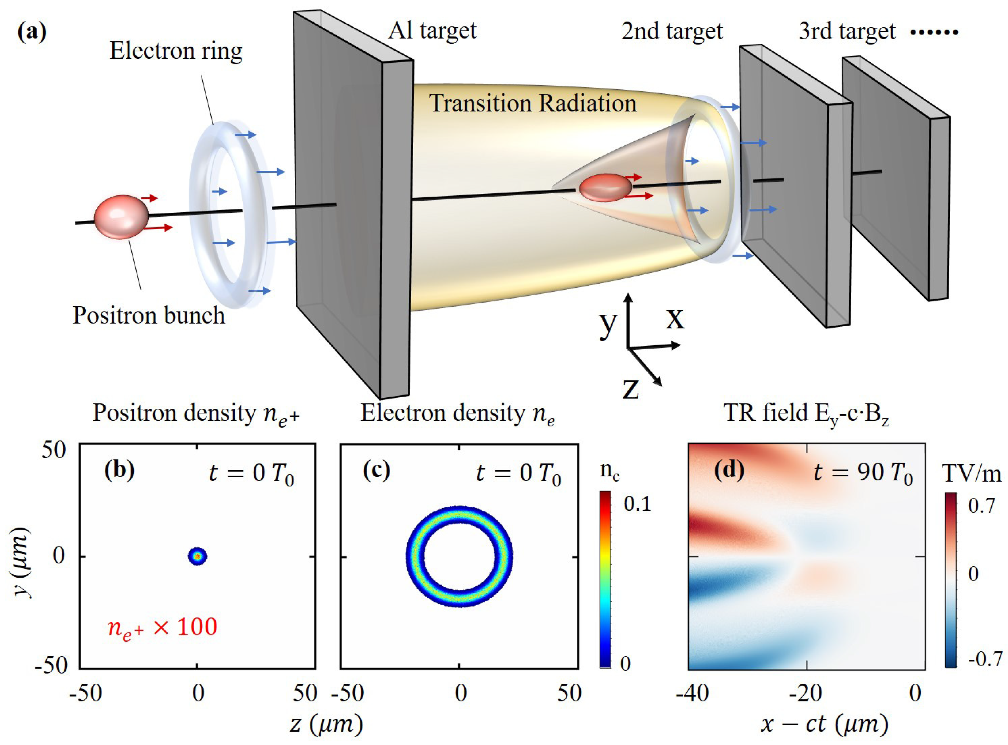
2.1. Overview of the Scheme

Here, by the use of multi-dimensional (3D) particle-in-cell (PIC) simulations, we present a novel multistage positron acceleration and confinement scheme driven by electron beam-generated THz radiation, as schematically shown in Figure 1a. In this scheme, CTR with THz frequency is first generated by the interaction of an injected high-energy hollow electron beam with an aluminum (Al) target, as shown in Figure 1b,c. The transverse electromagnetic field of the CTR has a special structure, which can push the positrons toward the propagation axis so that the divergence of the positron bunch can be well controlled. At the same time, the peculiar longitudinal field can simultaneously accelerate the positrons along the propagation axis. Since the CTR field gradually diverges and weakens with the propagation time, we can insert several Al targets along the propagation axis to refresh the THz radiation field by the remaining moderate-energy electrons so that the positrons can be further accelerated in a compact manner. With such a multistage THz acceleration scheme, not only are the positron average energy and the energy conversion efficiency from electrons to positrons improved but also the geometric emittance and energy dispersion of the injected positron bunch are well maintained.
To demonstrate the feasibility of our scheme, we first performed full 3D PIC simulations with the open-source code EPOCH, and carried out detailed parameter scanning with a series of 2D PIC simulations to verify the robustness of this multistage scheme. Our simulations indicated that the results of the 2D and 3D simulations are highly consistent. In the 2D PIC simulations, the size of the simulation box is 40 μ m × 120 μ m, and the size of the mesh grid is 2000 × 2400 . In the 3D simulations, the size of the simulation box is 40 μ m × 50 μ m × 50 μ m, and the corresponding mesh grid is 800 × 500 × 500 . The radius of the electron ring is set to 20 μ m, and the density distribution function is n e = n 1 × e x p ( x 2 / δ x 1 2 ( r r 0 ) 2 / δ r 1 2 ) . Here, n 1 = 0.1 n c is the peak density of the electron ring, r 0 = 20 μ m denotes the mean radius of the electron ring, δ x 1 = 5 μ m and δ r 1 = 2 μ m represent the longitudinal and transverse size of the bunch, respectively. Such donut-shaped electron rings can be acquired in ultra-intense Laguerre Gaussian laser interaction with plasmas [38,49], and the injected positron beam is also attainable from laser–plasma interactions as described in the introduction section. Although no laser is used in this simulation, the critical density of the plasma n c 1.2 × 10 27 m 3 and the period T 0 3.3 × 10 15 s are used for simplicity. The density distribution of the injected positron bunch is set as n e + = n 2 × e x p ( ( x 5 μ m ) 2 / δ x 2 2 r 2 / δ r 2 2 ) , where n 2 = 0.0001 n c , δ x 2 = 2 μ m and δ r 2 = 2 μ m. The initial energy of the positron beam is set to 100 MeV, the average energy of the electron beam is set to 2 GeV, and the energy of the electron beam ranges from 1 to 10 GeV in the following parametric studies. In the multistage acceleration scheme, the Al targets are placed with an interval 500 μ m, and the thickness of each Al target is 2 μ m.

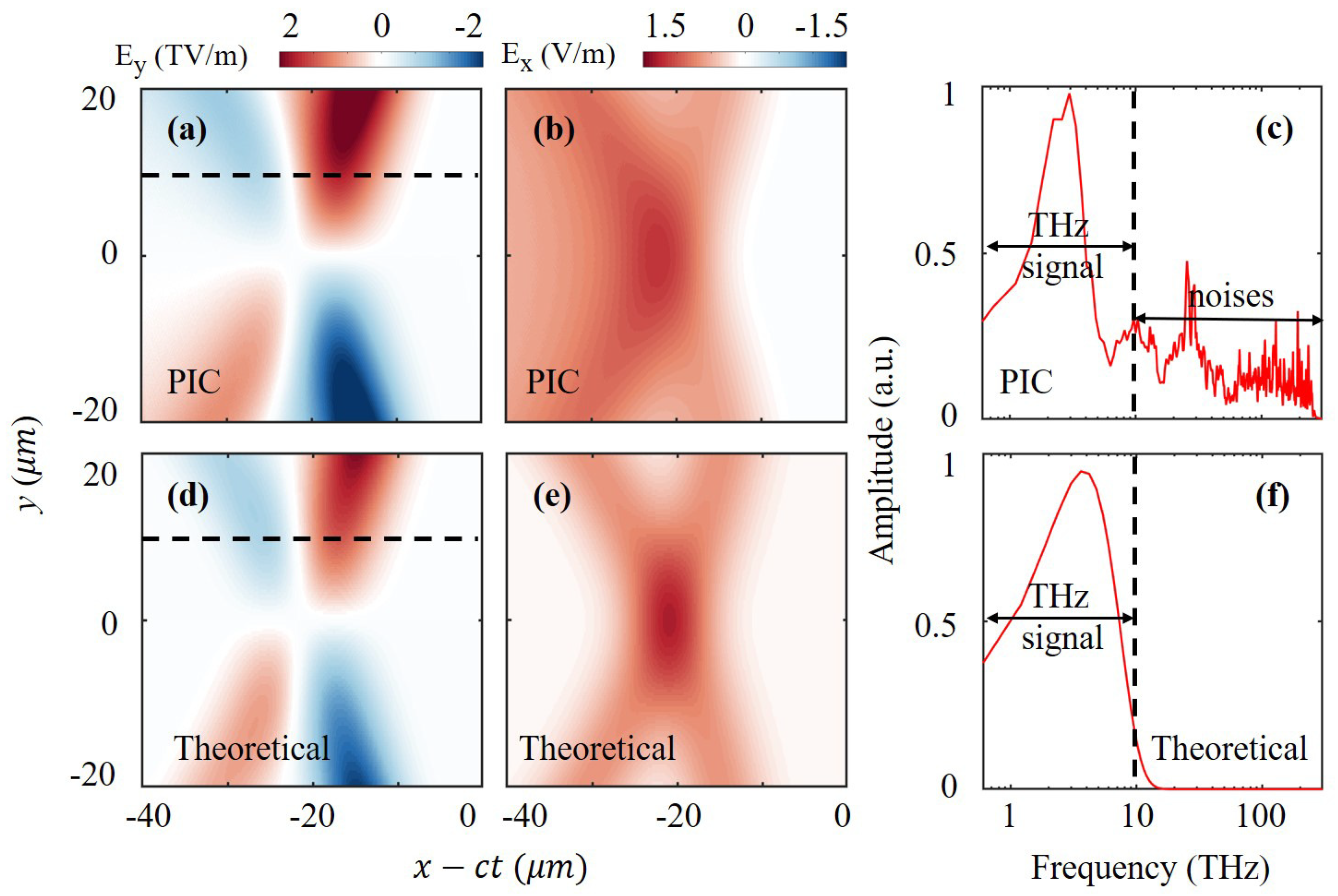
2.2. Generation of Coherent THz Radiation

As a hollow electron bunch passes through an Al target, strong transition radiation can be generated. In order to facilitate subsequent analysis of the radial forces exerted on the positrons, the E y field distribution in the z = 0 μ m plane obtained from the PIC simulations is presented in Figure 2a. While the acceleration fields of positrons are mainly provided by the longitudinal radiation field E x , the distribution of the E x field in the z = 0 μ m plane is shown in Figure 2b. For the purpose of analyzing the frequency composition of the CTR field, the electric field distribution E y at y = 10 μ m was extracted, as shown by the dotted line in Figure 2a, and the fast Fourier transform (FFT) was performed, as shown in Figure 2c. It is clear to see that the spectrum of the CTR field is mainly located in the THz band ranging from 0.1 THz to 10 THz, accompanied with some incoherent high-frequency signals [50].
When a single energetic electron ( γ 1 ) passes through the target surface, the electric field distribution at an observation point can be calculated by the following formulas [51]:
E r = q e 4 π ϵ 0 γ 2 ( r S 3 r S + 3 ) u ( c t R ) + β q e s i n θ c o s θ 2 π ϵ 0 R ( 1 β 2 c o s 2 θ ) δ ( c t R ) e c o s θ 2 π ϵ 0 r δ ( c t R ) ( γ 1 , β 1 ) ,
E x = q e 4 π ϵ 0 γ 2 ( x v e t S 3 x + v e t S + 3 ) u ( c t R ) + β q e s i n 2 θ 2 π ϵ 0 R ( 1 β 2 c o s 2 θ ) δ ( c t R ) e 2 π ϵ 0 R δ ( c t R ) ( γ 1 , β 1 ) .
Here, q e is the charge of a single electron, v e is the velocity of the electron, β = v e / c , c is the speed of light in vacuum, γ = 1 / 1 β 2 is the electron relativistic factor, and S = ( v e t x ) 2 + ( r / γ ) 2 , S + = ( v e t + x ) 2 + ( r / γ ) 2 ) and ϵ 0 are the vacuum permittivity. In particular, R represents the distance from the interaction point to the observation point, while r = y 2 + z 2 = R s i n θ and θ = a r c t a n ( y / z ) come from the cylindrical coordinate. In the above equations, the first item representing the Coulomb fields can be ignored in our calculations since it is insignificant when the relativistic factor is γ 1 . Since the wavelength of THz radiation is larger than the electron bunch size ( λ THz > δ x 1 ) , the individual electron’s low frequency transition radiation can be added coherently, and the observer sees the coherent superposition over the whole bunch [51]. The theoretical predications of E y and E x field in the x-y plane are shown in Figure 2d,e, respectively. For comparison, the 1D E y electric field distribution at y = 10 μ m was extracted from Figure 2d, and the frequency spectrum of the 1D signal is shown in Figure 2f. It is obvious that the theoretical signal consists of only the THz signal, and the power spectrum peaks at almost the same frequency with the PIC simulation signal as shown in Figure 2c.

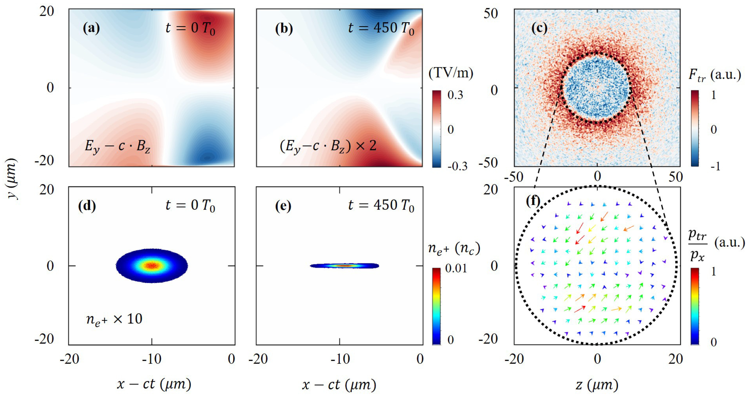
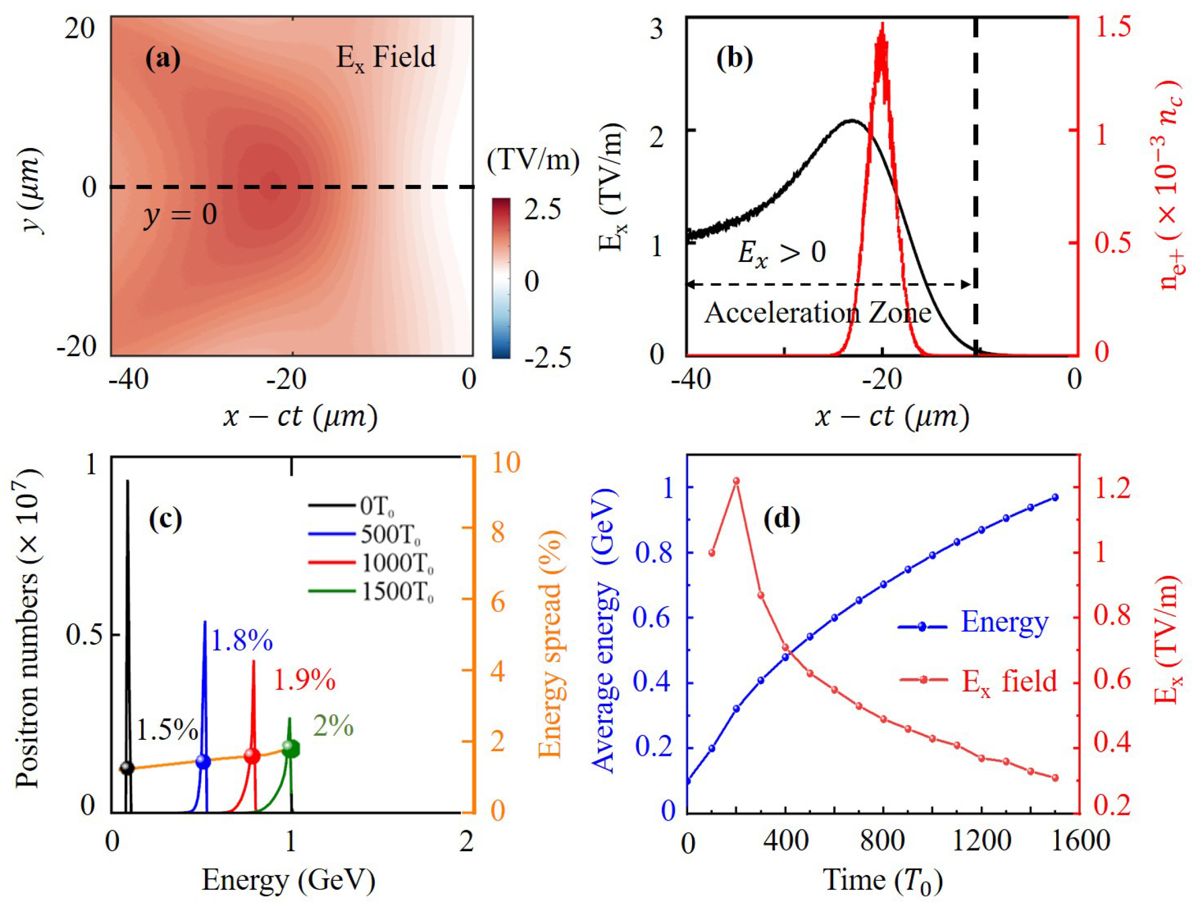
2.3. THz-Driven Positron Acceleration

As the injected positrons propagate forward along with the THz radiation, they are constrained by the electromagnetic force in the transverse direction. The distribution of the transverse electromagnetic field E y c · B z in the x-y plane at two different time points are shown in Figure 3a,b. We see that the transverse field can constantly compress the positrons toward the propagating axis y = 0 μ m despite the intensity decaying to half of the original value at t = 450 T 0 . Figure 3c distinctly shows the transverse force exerted on the positrons in the y-z plane. It can be seen that the dotted circle corresponds to the position of the electron ring, and the positrons located in the ring are compressed toward the axis by the radial force pointing to the center of the circle, while the positrons outside of the circle are pushed away from the center. During the interaction of positrons and the THz wave from t = 0 T 0 to t = 450 T 0 , the positron density increases from 0.001 n c to 0.01 n c , indicating that the positron beam is transversely compressed by at least 10 times, as shown in Figure 3d,e. Figure 3f illustrates the instantaneous transverse momentum distribution of positrons within the dashed circle in Figure 3c. We see that the positrons on the axis have only small transverse momentum and they travel almost exclusively forward, while the positrons around the axis have larger transverse momentum pointing toward the axis, expounding that the injected positron bunch is effectively focused as expected.
Besides the beam compression in the transverse direction, the positrons are also accelerated by the special strong longitudinal electric field E x , whose distribution in the x-y plane at the t = 0 T 0 is shown in Figure 4a. The maximum intensity of the E x field reaches 2.5 TV/m; hence, the corresponding instantaneous acceleration gradient for positrons reaches 2.5 TeV/m. Figure 4b exhibits the 1D positron density distribution and the 1D E x field distribution along the propagation axis (dashed line in Figure 4a). It is presented that the positron bunch locates exactly in the acceleration phase of E x > 0 and near the peak of E x field, guaranteeing the effective acceleration of positrons. Within 1500 T 0 , these positrons located in the acceleration region can be accelerated from 100 MeV to 1 GeV, as shown in Figure 4c. Interestingly, during the positron bunch’s acceleration with the CTR field, its relative energy spread remains within δ E / E 2 % , indicating that the positron beam is uniformly accelerated by the THz field and the monochromaticity of the positron bunch is well maintained in the whole acceleration process. Here, δ E denotes the full width at half maximum (FWHM) of the spectrum, and E represents the peak energy of the spectrum. This property of the generated positron bunch is very desirable in further studies and could benefit the follow-up operations on the positron bunch. Since the CTR wave diverges and decays with the propagation time, the time evolution of the positron bunch average energy and the 50 T 0 -averaged acceleration gradient are plotted, as shown in Figure 4d. After 400 T 0 propagation, the acceleration gradient of the THz field decays rapidly to half of the maximum value, and the energy increase in the positrons also begins to slow down. From 1000 T 0 to 1500 T 0 , the acceleration gradient decays to 10% of the peak value, and the average positron energy increases by only 100 MeV. Although the positrons are not out of the acceleration phase after propagating along with the THz wave for 1500 T 0 , the acceleration efficiency is not so promising after 1000 T 0 . In order to maintain the positron acceleration and its beam quality, we performed a series of PIC simulations to optimize the initial parameters.

3. Discussion

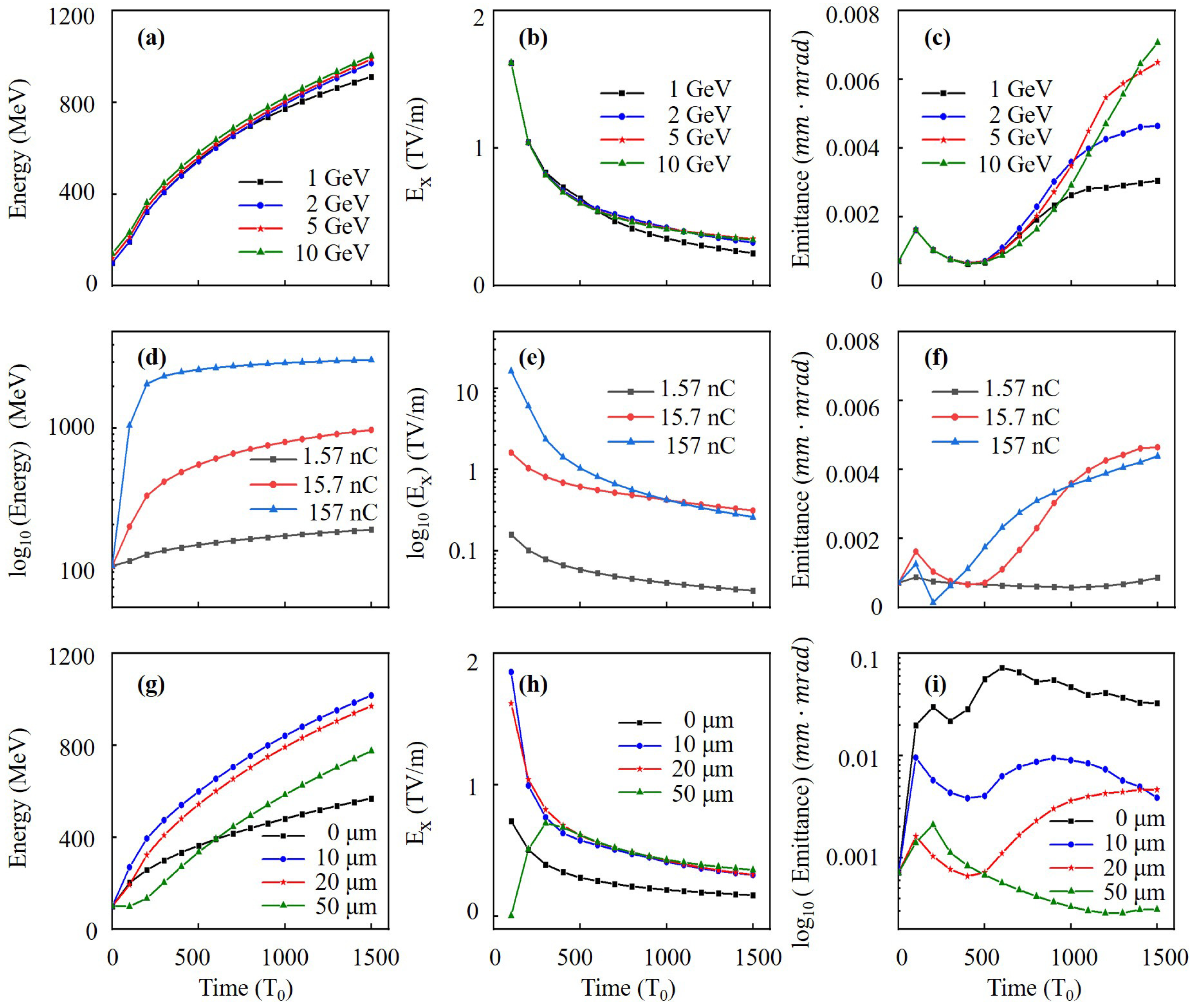
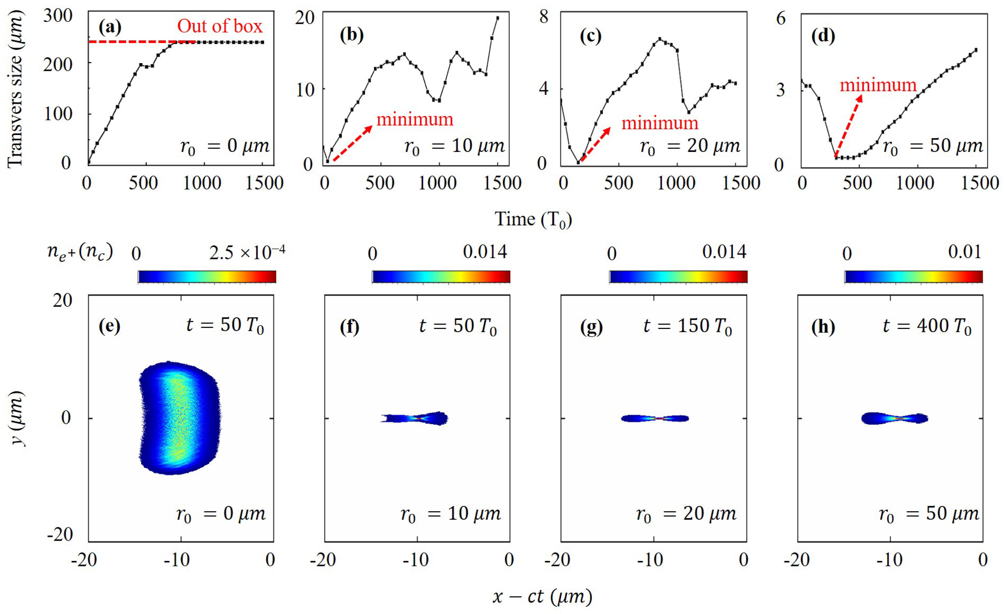
3.1. Parametric Influences

In order to increase the average positron energy, it would be reasonable to increase the energy of the drive electron beam. Therefore, different electron beams with the energy in the 1 GeV–10 GeV range are considered in the simulations to enhance the THz radiation and drive the positron acceleration. Evolution of the average positron energy and the acceleration gradient over time are presented in Figure 5a,b, respectively. It is shown that the influences of electron energy on the resulting THz field intensity and positron beam energy are inappreciable. This conclusion is consistent with Equations (1) and (2) because the energy of the drive particles can only change the value of the first term, i.e., the Coulomb field, which is, however, insignificant in the cases of γ 1 . For example, when a 1 GeV electron beam is employed, the positron energy finally peaks at 912 MeV, slightly lower than the value of 980 MeV in other cases. Moreover, the theoretical calculation of d W e / d ω = ( 2 r e m e c / π ) l n ( γ ) also indicates that the CTR energy depends weakly on the electron energy d W e l n ( γ ) [50]; hence, the longitudinal electric field intensity shows even a weaker dependence of E x l n ( γ ) . Here, d W e / d ω represents the spectral energy of CTR from a single electron, and r e and m e denote the classical electron radius and electron mass, respectively. Therefore, in the cases of γ 1 , the drive beam energy shows no remarkable influence on the positron acceleration and determines only the saturation value of the positron energy.
Besides the longitudinal acceleration, the transverse confinement of positrons is equally important during the acceleration process as we analyzed above. Figure 5c shows the variation of the positron beam geometric emittance with time at different drive beam energies. Here, the geometric emittance of the positron beam can be calculated by ϵ y = y 2 θ y 2 y θ y 2 , where y and θ y represent the particle position and angle between its momentum and the y axis, respectively. For the first 500 T 0 , all positron beams can be well constrained by the transverse THz field, and the emittance gradually decreases to a minimum of 0.0009 mm· mrad. During the subsequent beam acceleration and propagation, the positron beam emittances obviously increase with the energy of the drive electron beam. However, they are still less than 0.007 mm· mrad for, for instance, a 10 GeV driven beam. This indicates that although the positron beams are not out of the acceleration phase in all cases, they gradually get out of the transverse confining phase after 500 T 0 , and the higher the energy of the driving electron beams, the more the positrons fall behind the confinement phase.
It should be noticed that the total CTR field can be considered the superposition of the radiation of all particles from the drive beam as mentioned above. Therefore, the beam density and charge are expected to have great impact on the THz radiation and the acceleration process. In order to find out the correlations between them, three different electron rings with the same energy (2 GeV) and same radii ( r 0 = 20 μ m) but with different peak density parameter n 1 ranging from 0.01 n c to 1 n c (corresponding charge from 1.57 nC to 157 nC) are set as drive beams in three separate simulations. Figure 5a,b exhibit that both the positron energy and the E x field of the CTR generated present more than an order of magnitude difference when driven by the electron beams with different densities. Such results are predictable since the CTR field energy of the whole beam equals N e 2 times the CTR energy of a single electron, as indicated by the formula d 2 W CTR / ( d ω d Ω ) = N e 2 d 2 W e / ( d ω d Ω ) [52]. Here, N e denotes the electron numbers within the drive beam, and d 2 W CTR / ( d ω d Ω ) and d 2 W e / ( d ω d Ω ) represent the CTR energy of a whole bunch and a single electron, respectively. It is intriguing that the geometric emittance maintains the original value when driven by the electron beam with density of 0.01 n c . Correspondingly, the emittance at t = 1500 T 0 shows only slight difference when driven by the 0.1 n c and 1 n c beams, as shown in Figure 5f. Despite the drive beam with the density of 0.01 n c providing only 100 MeV energy increase for positrons in 1500 T 0 , the positron beam emittance remains almost unchanged, which is also crucial for the subsequent multistage acceleration of the positron beam.
In addition to the energy and density, the effect of the electron ring radius should also be taken into account in experiments. This is of significance for designing the injected beams. Therefore, four electron rings of different mean radii r 0 are considered in simulations to drive the positron beam acceleration, namely r 0 = 0 μ m (normal electron beam), 10 μ m, 20 μ m, and 50 μ m, respectively. It is found that when r 0 0 , the smaller the electron ring radius, the faster the positrons get accelerated and the higher the peak energy that can be achieved. Correspondingly, the positron beam emittance slightly increases, as shown in Figure 5g–i). Interestingly, with the drive beam of r 0 = 50 μ m, the positrons can be hardly accelerated within the first 100 T 0 , and the acceleration field gradually increases from 100 to 300 T 0 . This is because the CTR field has an evolutionary process. When the radius of the electron ring is too large, it needs more time for the field to travel and affect the positron beam located at the center. For a normal electron beam with r 0 = 0 , although the positrons can be accelerated as well, the peak energy is much lower, and the emittance of the positron beam is increased by two orders of magnitude. In order to show the influence of different electron ring radii on the positron beam size during the acceleration process, the evolutions of positron transverse size over time are plotted, as shown in Figure 6a–d. It is clear to see that when a hollow electron beam is used as a driver, the transverse size of the positron beam tends to decrease first and then increase, and the larger the electron ring radius is, the better the positrons are constrained, as illustrated in Figure 6b–d. On the contrary, the normal electron beam cannot constrain the positrons, and the transverse size of the positron beam increases continuously from the beginning, and the beam gets out of the simulation box after 700 T 0 , as shown in Figure 6a. Figure 6f–h present the positron density distributions in the x-y plane, corresponding to the moment when the transverse size is minimal as marked in Figure 6b–d. Note that Figure 6e presents the positron beam distribution as the same moment as Figure 6f since there is no beam confinement in Figure 6a. Though the normal electron beam can accelerate the positrons as well, it is not able to constrain the positrons transversely during the beam acceleration, resulting in the deteriorating of the positron beam quality.

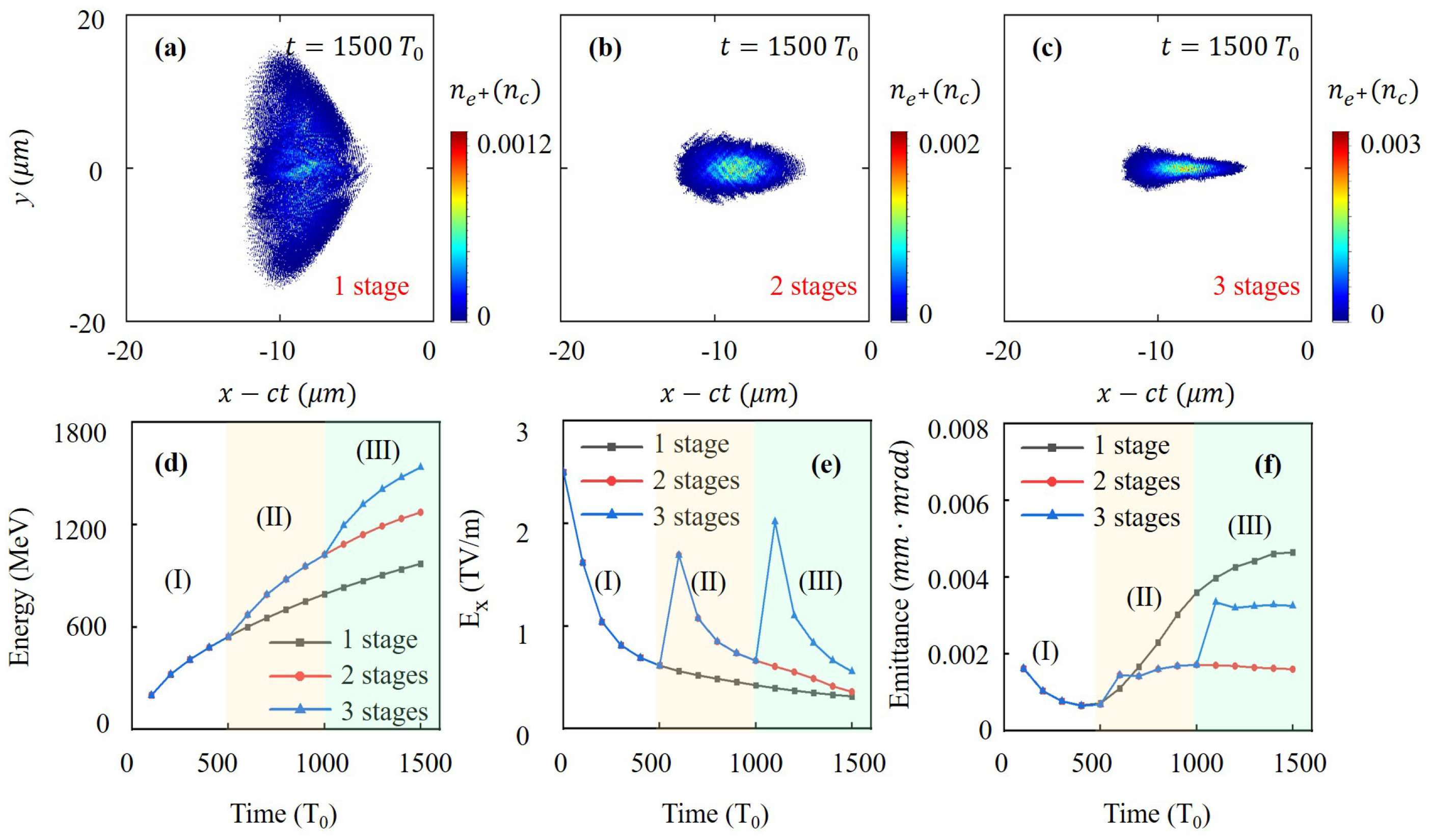
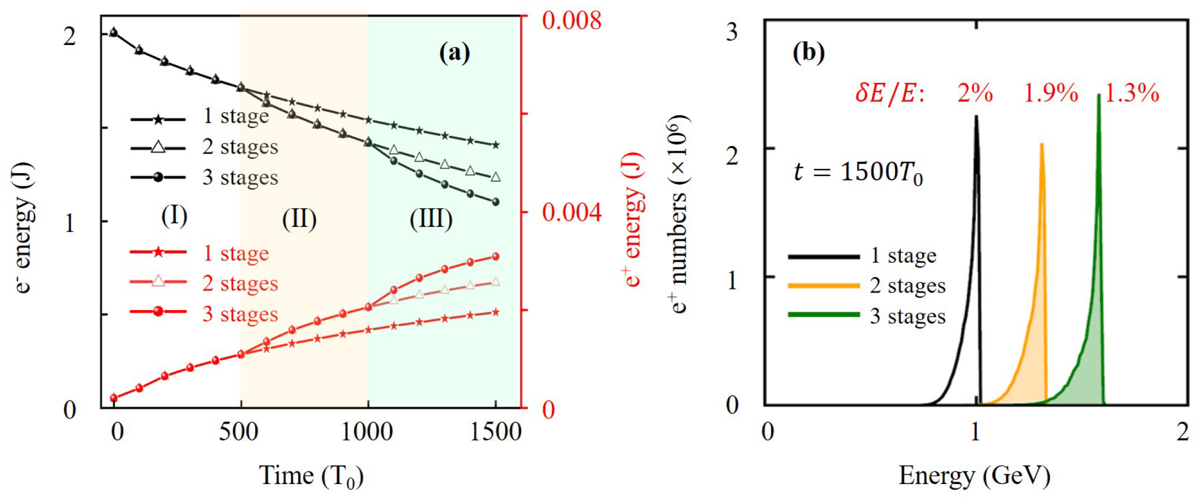
3.2. Multistage Positron Acceleration

As we discussed above, a high-quality positron beam acceleration requires several considerations. First, the drive electron beam should possess a hollow structure; otherwise, it cannot constrain the positron beam during its acceleration. Second, an appropriate driven energy is required. If the drive beam energy is too high, the acceleration gradient does not increase significantly, and a faster dephasing of the positron beam occurs. Finally, the density or charge of the electron beam plays a key role in the THz radiation and thus the positron acceleration. An electron beam with lower density leads to a longer acceleration duration and a lower energy gain, but the geometric emittance of the positron beam gets better. In order to maintain the phase-locked acceleration of the positron beam, the positrons should remain in both the longitudinal acceleration phase and the transverse confinement phase. There are two possible approaches to this goal. One is to choose appropriate drive beam parameters, including the beam energy, density and the ring radii. Another is to employ multiple Al targets to refresh the radiation field and re-accelerate the positron beam in a multistage way. This can be done before the positron beam acceleration approaches saturation and its transverse size starts to increase, which is well demonstrated by the 3D PIC simulation in the following.
In order to accelerate the positrons in a multistage manner, an electron beam with the energy of 2 GeV, density of n 1 = 0.1 n c and ring radii of r 0 = 20 μ m are employed as a drive, and three Al targets with 500 μ m distance in x direction are inserted, respectively, in three different simulations. Figure 7a–c present the density distribution of positrons at t = 1500 T 0 after one, two and three stages of acceleration, respectively. It is clear to see that the transverse size of the positron beams decreases significantly with the increase in the Al targets, indicating that the transverse confinement due to the transverse force of the CTR field becomes more and more effective. Each additional Al target increases the positron energy gain by nearly 200 MeV, as shown in Figure 7d. This is because the CTR field that has been attenuated and diverged in the previous stage can be refreshed again when the electron beam passes through a new Al target, as shown in Figure 7e. In particular, in the single-stage acceleration, the geometric emittance of the positron beam continues to increase after 500 T 0 . However, in the multistage acceleration regime, the positron beam emittances only increase slightly at the beginning of each stage but stay almost unchanged in the subsequent acceleration, which proves that the multistage acceleration can effectively maintain the confinement phase of the positron beam. Figure 8a presents the time variation of the total electron and positron energy when using different acceleration stages. As we can see in this figure, the energy conversion efficiency from electrons to positrons can be calculated as 0.097%, 0.13% and 0.15% corresponding to one, two and three acceleration stages, respectively. Each additional stage provides around 0.025% higher energy conversion efficiency. Furthermore, it is intriguing to find out that the FWHM energy spread can be narrowed with increasing acceleration stages, as indicated by the positron energy spectrum in Figure 8b. All in all, our additional simulations show that using two or more Al targets at appropriate locations for the multistage acceleration of the positron beam can not only improve the conversion efficiency but also decrease the transverse emittance and narrow the energy spread of the positron beam so that the phase-locked acceleration of the positron beam can be maintained for a much longer time.

4. Conclusions

In this paper, a multistage phase-locked positron acceleration scheme driven by a hollow electron beam is demonstrated by full 3D-PIC simulations. Taking single-stage acceleration as an example, the generation process of the CTR field is demonstrated in the first place. From the FFT analysis, it is found that the frequency component of CTR is mainly in the THz band, and the CTR field obtained from PIC simulations is in excellent agreement with the theoretical results estimated by Equations (1) and (2). Then, by analyzing the transverse and longitudinal forces exerted on the positrons, we find that the positrons experience phase-locked acceleration in the THz field, i.e., simultaneously in the transverse confinement phase and longitudinal acceleration phase. Moreover, a series of PIC simulation results initiated with different electron beam parameters are performed to demonstrate the robustness of this scheme. By varying the radii of the electron rings, it is shown that the acceleration gradients of the hollow drive beams are higher than that of the normal electron beam, and the positrons can be better confined with the hollow drive beam. However, an excessively large ring radius will reduce the acceleration efficiency because it takes more time (around 300 T 0 when r e = 50 μ m) for the CTR field to interact with the positrons at the center of the ring. It is shown that a higher density electron ring surely can provide larger acceleration gradients, but this will speed up the dephasing of the transverse confinement. In the case of γ 1 , the energy of the electron beam does not significantly alter the acceleration gradient, and an overly high energy drive beam will make the positron beams leave the confinement phase more quickly. Finally, we keep the electron and positron beam parameters unchanged and alter the number of inserted Al targets in three independent simulations. The positron acceleration results after one, two and three acceleration stages are compared. For each additional step of acceleration, the positron energy can increase by nearly 200 MeV, and the transverse size is better controlled. In summary, this multistage acceleration scheme can effectively accelerate the positrons while maintaining the energy spread and the geometric emittance of the injected positron beam. Although a hollow electron beam is more difficult to obtain than the ordinary ones, they are already used to drive wakefields to accelerate positrons [41]. Other research also showed that a hollow electron beam can also be obtained from a Laguerre Gaussian laser-driven wakefield [38] or from a right-hand circularly polarized Laguerre Gaussian laser interaction with near critical density plasma [49]. Such a compact multistage positron acceleration scheme for GeV positron energies may potentially benefit the research in the field of fundamental physics and nonlinear QED studies.

Author Contributions

Conceptualization, J.Z. and T.-P.Y.; methodology, J.Z. and T.-P.Y.; software, J.Z. and H.Z.; validation, L.-X.H., F.-Q.S. and T.-P.Y.; formal analysis, J.Z.; investigation, Y.-T.H., H.Z. and Y.L.; resources, F.-Q.S. and T.-P.Y.; data curation, L.-X.H.; writing—original draft preparation, J.Z.; writing—review and editing, T.-P.Y.; visualization, J.Z.; supervision, T.-P.Y.; project administration, T.-P.Y.; funding acquisition, L.-X.H., F.-Q.S. and T.-P.Y. All authors have read and agreed to the published version of the manuscript.

Funding

This work was supported by the National Key R&D Program of China (Grant No. 2018YFA0404802), National Natural Science Foundation of China (Grant No. 12135009; Grant No. 12105362), and The Science and Technology Innovation Program of Hunan Province (Grant No. 2020RC4020); Natural Science Foundation of Hunan Province (Grant No. 2021JJ40653); Hunan Provincial Research and Innovation Foundation for Graduate Students (Grant No. CX20200002).

Institutional Review Board Statement

Not applicable.

Informed Consent Statement

Not applicable.

Data Availability Statement

Data underlying the results presented in this paper are not publicly available at this time but may be obtained from the authors upon reasonable request.

Acknowledgments

We acknowledge the access to the EPOCH code developed by University of Warwick.

Conflicts of Interest

The funders had no role in the design of the study; in the collection, analyses, or interpretation of data; in the writing of the manuscript; or in the decision to publish the results.

References

  1. Dirac, P.A. The Quantum Theory of the Electron. Proc. R. Soc. Lond. A 1928, 117, 610–624. [Google Scholar]
  2. Wu, Z.; de Krom, T.; Colombi, G.; Chaykina, D.; van Hattem, G.; Schut, H.; Dickmann, M.; Egger, W.; Hugenschmidt, C.; Brück, E.; et al. Formation of Vacancies and Metallic-like Domains in Photochromic Rare-Earth Oxyhydride Thin Films Studied by in-Situ Illumination Positron Annihilation Spectroscopy. Phys. Rev. Mater. 2022, 6, 065201. [Google Scholar] [CrossRef]
  3. Guedj, E.; McGonigal, A.; Vaugier, L.; Mundler, O.; Bartolomei, F. Metabolic Brain PET Pattern Underlying Hyperkinetic Seizures. Epilepsy Res. 2012, 101, 237–245. [Google Scholar] [CrossRef] [PubMed]
  4. Treglia, G.; Piccardo, A.; Garibotto, V. [18F]FDOPA Positron Emission Tomography for Cardiac Innervation Imaging: A New Way or a Dead-End Street? Clin. Auton. Res. 2022, 32, 399–401. [Google Scholar] [CrossRef] [PubMed]
  5. Dickmann, M.; Egger, W.; Kögel, G.; Vohburger, S.; Hugenschmidt, C. Upgrade of the NEPOMUC Remoderator. Acta Phys. Pol. A 2020, 137, 149–151. [Google Scholar] [CrossRef]
  6. Danielson, J.R.; Dubin, D.H.E.; Greaves, R.G.; Surko, C.M. Plasma and Trap-Based Techniques for Science with Positrons. Rev. Mod. Phys. 2015, 87, 247–306. [Google Scholar] [CrossRef] [Green Version]
  7. Wardle, J.F.C.; Homan, D.C.; Ojha, R.; Roberts, D.H. Electron–Positron Jets Associated with the Quasar 3C279. Nature 1998, 395, 457–461. [Google Scholar] [CrossRef]
  8. Shiltsev, V.; Zimmermann, F. Modern and Future Colliders. Rev. Mod. Phys. 2021, 93, 015006. [Google Scholar] [CrossRef]
  9. Schwinger, J. On Gauge Invariance and Vacuum Polarization. Phys. Rev. 1951, 82, 664–679. [Google Scholar] [CrossRef]
  10. Bethe, H.A.; Heitler, W. On the Stopping of Fast Particles and on the Creation of Positive Electrons. Proc. R. Soc. Lond. A 1934, 146, 83–112. [Google Scholar]
  11. Cowan, T.; Perry, M.; Key, M.; Ditmire, T.; Hatchett, S.; Henry, E.; Moody, J.; Moran, M.; Pennington, D.; Phillips, T.; et al. High Energy Electrons, Nuclear Phenomena and Heating in Petawatt Laser-Solid Experiments. Laser Part. Beams 1999, 17, 773–783. [Google Scholar] [CrossRef] [Green Version]
  12. Xu, Z.; Yi, L.; Shen, B.; Xu, J.; Ji, L.; Xu, T.; Zhang, L.; Li, S.; Xu, Z. Driving Positron Beam Acceleration with Coherent Transition Radiation. Commun. Phys. 2020, 3, 191. [Google Scholar] [CrossRef]
  13. Shearer, J.W.; Garrison, J.; Wong, J.; Swain, J.E. Pair Production by Relativistic Electrons from an Intense Laser Focus. Phys. Rev. A 1973, 8, 1582–1588. [Google Scholar] [CrossRef]
  14. Breit, G.; Wheeler, J.A. Collision of Two Light Quanta. Phys. Rev. 1934, 46, 1087–1091. [Google Scholar] [CrossRef]
  15. Bula, C.; McDonald, K.T.; Prebys, E.J.; Bamber, C.; Boege, S.; Kotseroglou, T.; Melissinos, A.C.; Meyerhofer, D.D.; Ragg, W.; Burke, D.L.; et al. Observation of Nonlinear Effects in Compton Scattering. Phys. Rev. Lett. 1996, 76, 3116–3119. [Google Scholar] [CrossRef] [PubMed] [Green Version]
  16. Burke, D.L.; Field, R.C.; Horton-Smith, G.; Spencer, J.E.; Walz, D.; Berridge, S.C.; Bugg, W.M.; Shmakov, K.; Weidemann, A.W.; Bula, C.; et al. Positron Production in Multiphoton Light-by-Light Scattering. Phys. Rev. Lett. 1997, 79, 1626. [Google Scholar] [CrossRef]
  17. Bamber, C.; Boege, S.J.; Koffas, T.; Kotseroglou, T.; Melissinos, A.C.; Meyerhofer, D.D.; Reis, D.A.; Ragg, W.; Bula, C.; McDonald, K.T.; et al. Studies of Nonlinear QED in Collisions of 46.6 GeV Electrons with Intense Laser Pulses. Phys. Rev. D 1999, 60, 092004. [Google Scholar] [CrossRef] [Green Version]
  18. Adam, J.; Adamczyk, L.; Adams, J.R.; Adkins, J.K.; Agakishiev, G.; Aggarwal, M.M.; Ahammed, Z.; Alekseev, I.; Anderson, D.M.; Aparin, A.; et al. Measurement of e + e-Momentum and Angular Distributions from Linearly Polarized Photon Collisions. Phys. Rev. Lett. 2021, 127, 052302. [Google Scholar] [CrossRef]
  19. Ridgers, C.P.; Brady, C.S.; Duclous, R.; Kirk, J.G.; Bennett, K.; Arber, T.D.; Bell, A.R. Dense Electron-Positron Plasmas and Bursts of Gamma-Rays from Laser-Generated Quantum Electrodynamic Plasmas. Phys. Plasmas 2013, 20, 056701. [Google Scholar] [CrossRef] [Green Version]
  20. Nerush, E.N.; Kostyukov, I.Y.; Fedotov, A.M.; Narozhny, N.B.; Elkina, N.V.; Ruhl, H. Laser Field Absorption in Self-Generated Electron-Positron Pair Plasma. Phys. Rev. Lett. 2011, 106, 035001. [Google Scholar] [CrossRef]
  21. Grismayer, T.; Vranic, M.; Martins, J.L.; Fonseca, R.A.; Silva, L.O. Laser Absorption via QED Cascades in Counter Propagating Laser Pulses. Phys. Plasmas 2016, 23, 056706. [Google Scholar] [CrossRef] [Green Version]
  22. Lobet, M.; Davoine, X.; d’Humières, E.; Gremillet, L. Generation of High-Energy Electron-Positron Pairs in the Collision of a Laser-Accelerated Electron Beam with a Multipetawatt Laser. Phys. Rev. Accel. Beams 2017, 20, 043401. [Google Scholar] [CrossRef]
  23. Zhu, X.L.; Yu, T.P.; Sheng, Z.M.; Yin, Y.; Turcu, I.C.E.; Pukhov, A. Dense GeV Electron–Positron Pairs Generated by Lasers in near-Critical-Density Plasmas. Nat. Commun. 2016, 7, 13686. [Google Scholar] [CrossRef] [PubMed] [Green Version]
  24. Yu, J.Q.; Lu, H.Y.; Takahashi, T.; Hu, R.H.; Gong, Z.; Ma, W.J.; Huang, Y.S.; Chen, C.E.; Yan, X.Q. Creation of Electron-Positron Pairs in Photon-Photon Collisions Driven by 10-PW Laser Pulses. Phys. Rev. Lett. 2019, 122, 014802. [Google Scholar] [CrossRef] [PubMed] [Green Version]
  25. Zhao, J.; Hu, Y.T.; Lu, Y.; Zhang, H.; Hu, L.X.; Zhu, X.L.; Sheng, Z.M.; Turcu, I.C.E.; Pukhov, A.; Shao, F.Q.; et al. All-Optical Quasi-Monoenergetic GeV Positron Bunch Generation by Twisted Laser Fields. Commun. Phys. 2022, 5, 1–10. [Google Scholar] [CrossRef]
  26. Del Sorbo, D.; Blackman, D.R.; Capdessus, R.; Small, K.; Slade-Lowther, C.; Luo, W.; Duff, M.J.; Robinson, A.P.L.; McKenna, P.; Sheng, Z.M.; et al. Efficient Ion Acceleration and Dense Electron–Positron Plasma Creation in Ultra-High Intensity Laser-Solid Interactions. New J. Phys. 2018, 20, 033014. [Google Scholar] [CrossRef]
  27. Zhu, X.L.; Chen, M.; Yu, T.P.; Weng, S.M.; He, F.; Sheng, Z.M. Collimated GeV Attosecond Electron–Positron Bunches from a Plasma Channel Driven by 10 PW Lasers. Matter Radiat. Extrem. 2019, 4, 014401. [Google Scholar] [CrossRef] [Green Version]
  28. Danson, C.N.; Haefner, C.; Bromage, J.; Butcher, T.; Chanteloup, J.C.F.; Chowdhury, E.A.; Galvanauskas, A.; Gizzi, L.A.; Hein, J.; Hillier, D.I.; et al. Petawatt and Exawatt Class Lasers Worldwide. High Power Laser Sci. Eng. 2019, 7, e54. [Google Scholar] [CrossRef]
  29. Wang, X.; Liu, X.; Lu, X.; Chen, J.; Long, Y.; Li, W.; Chen, H.; Chen, X.; Bai, P.; Li, Y.; et al. 13.4 Fs, 0.1 Hz OPCPA Front End for the 100 PW-Class Laser Facility. Ultrafast Sci. 2022, 2022, 9894358. [Google Scholar] [CrossRef]
  30. Yoon, J.W.; Kim, Y.G.; Choi, I.W.; Sung, J.H.; Lee, H.W.; Lee, S.K.; Nam, C.H. Realization of Laser Intensity over 10 23 W/Cm 2. Optica 2021, 8, 630. [Google Scholar] [CrossRef]
  31. Lureau, F.; Matras, G.; Chalus, O.; Derycke, C.; Morbieu, T.; Radier, C.; Casagrande, O.; Laux, S.; Ricaud, S.; Rey, G.; et al. High-Energy Hybrid Femtosecond Laser System Demonstrating 2 × 10 PW Capability. High Pow Laser Sci. Eng. 2020, 8, e43. [Google Scholar] [CrossRef]
  32. Yakimenko, V.; Alsberg, L.; Bong, E.; Bouchard, G.; Clarke, C.; Emma, C.; Green, S.; Hast, C.; Hogan, M.J.; Seabury, J.; et al. FACET-II Facility for Advanced Accelerator Experimental Tests. Phys. Rev. Accel. Beams 2019, 22, 101301. [Google Scholar] [CrossRef] [Green Version]
  33. Tanaka, K.A.; Spohr, K.M.; Balabanski, D.L.; Balascuta, S.; Capponi, L.; Cernaianu, M.O.; Cuciuc, M.; Cucoanes, A.; Dancus, I.; Dhal, A.; et al. Current Status and Highlights of the ELI-NP Research Program. Matter Radiat. Extrem. 2020, 5, 024402. [Google Scholar] [CrossRef] [Green Version]
  34. Benedetti, C.; Bulanov, S.S.; Esarey, E.; Gonsalves, C.G.R.G.A.J.; Jacobs, P.M.; Knapen, S.; Nachman, B.; Nakamura, K.; Griso, S.P.; Schroeder, C.B.; et al. Whitepaper Submitted to Snowmass21: Advanced Accelerator Linear Collider Demonstration Facility at Intermediate Energy. arXiv 2022, arXiv:2203.08425. [Google Scholar]
  35. Gonsalves, A.J.; Nakamura, K.; Daniels, J.; Benedetti, C.; Pieronek, C.; de Raadt, T.C.H.; Steinke, S.; Bin, J.H.; Bulanov, S.S.; van Tilborg, J.; et al. Petawatt Laser Guiding and Electron Beam Acceleration to 8 GeV in a Laser-Heated Capillary Discharge Waveguide. Phys. Rev. Lett. 2019, 122, 084801. [Google Scholar] [CrossRef] [PubMed] [Green Version]
  36. Esirkepov, T.; Bulanov, S.V.; Yamagiwa, M.; Tajima, T. Electron, Positron, and Photon Wakefield Acceleration: Trapping, Wake Overtaking, and Ponderomotive Acceleration. Phys. Rev. Lett. 2006, 96, 014803. [Google Scholar] [CrossRef]
  37. Gessner, S.; Adli, E.; Allen, J.M.; An, W.; Clarke, C.I.; Clayton, C.E.; Corde, S.; Delahaye, J.P.; Frederico, J.; Green, S.Z.; et al. Demonstration of a Positron Beam-Driven Hollow Channel Plasma Wakefield Accelerator. Nat. Commun. 2016, 7, 11785. [Google Scholar] [CrossRef]
  38. Vieira, J.; Mendonça, J.T. Nonlinear Laser Driven Donut Wakefields for Positron and Electron Acceleration. Phys. Rev. Lett. 2014, 112, 215001. [Google Scholar] [CrossRef]
  39. Corde, S.; Adli, E.; Allen, J.M.; An, W.; Clarke, C.I.; Clayton, C.E.; Delahaye, J.P.; Frederico, J.; Gessner, S.; Green, S.Z.; et al. Multi-Gigaelectronvolt Acceleration of Positrons in a Self-Loaded Plasma Wakefield. Nature 2015, 524, 442–445. [Google Scholar] [CrossRef]
  40. Zhou, S.; Hua, J.; Lu, W.; Mori, W.B.; Joshi, C. High Efficiency Uniform Wakefield Acceleration of a Positron Beam Using Stable Asymmetric Mode in a Hollow Channel Plasma. Phys. Rev. Lett. 2021, 127, 174801. [Google Scholar] [CrossRef]
  41. Jain, N.; Antonsen, T.M.; Palastro, J.P. Positron Acceleration by Plasma Wakefields Driven by a Hollow Electron Beam. Phys. Rev. Lett. 2015, 115, 195001. [Google Scholar] [CrossRef] [PubMed] [Green Version]
  42. Yan, Y.; Wu, Y.; Chen, J.; Yu, M.; Dong, K.; Gu, Y. Positron Acceleration by Sheath Field in Ultra-Intense Laser–Solid Interactions. Plasma Phys. Control. Fusion 2017, 59, 045015. [Google Scholar] [CrossRef]
  43. Hibberd, M.T.; Healy, A.L.; Lake, D.S.; Georgiadis, V.; Smith, E.J.H.; Finlay, O.J.; Pacey, T.H.; Jones, J.K.; Saveliev, Y.; Walsh, D.A.; et al. Acceleration of Relativistic Beams Using Laser-Generated Terahertz Pulses. Nat. Photonics 2020, 14, 755–759. [Google Scholar] [CrossRef]
  44. Xu, H.; Yan, L.; Du, Y.; Huang, W.; Tian, Q.; Li, R.; Liang, Y.; Gu, S.; Shi, J.; Tang, C. Cascaded High-Gradient Terahertz-Driven Acceleration of Relativistic Electron Beams. Nat. Photonics 2021, 15, 426–430. [Google Scholar] [CrossRef]
  45. Tang, H.; Zhao, L.; Zhu, P.; Zou, X.; Qi, J.; Cheng, Y.; Qiu, J.; Hu, X.; Song, W.; Xiang, D.; et al. Stable and Scalable Multistage Terahertz-Driven Particle Accelerator. Phys. Rev. Lett. 2021, 127, 074801. [Google Scholar] [CrossRef]
  46. Kealhofer, C.; Schneider, W.; Ehberger, D.; Ryabov, A.; Krausz, F.; Baum, P. All-Optical Control and Metrology of Electron Pulses. Science 2016, 352, 429–433. [Google Scholar] [CrossRef]
  47. Nanni, E.A.; Huang, W.R.; Hong, K.H.; Ravi, K.; Fallahi, A.; Moriena, G.; Dwayne Miller, R.J.; Kärtner, F.X. Terahertz-Driven Linear Electron Acceleration. Nat. Commun. 2015, 6, 8486. [Google Scholar] [CrossRef] [Green Version]
  48. Sampath, A.; Davoine, X.; Corde, S.; Gremillet, L.; Gilljohann, M.; Sangal, M.; Keitel, C.H.; Ariniello, R.; Cary, J.; Ekerfelt, H.; et al. Extremely Dense Gamma-Ray Pulses in Electron Beam-Multifoil Collisions. Phys. Rev. Lett. 2021, 126, 064801. [Google Scholar] [CrossRef]
  49. Hu, Y.T.; Zhao, J.; Zhang, H.; Lu, Y.; Wang, W.Q.; Hu, L.X.; Shao, F.Q.; Yu, T.P. Attosecond γ-Ray Vortex Generation in near-Critical-Density Plasma Driven by Twisted Laser Pulses. Appl. Phys. Lett. 2021, 118, 054101. [Google Scholar] [CrossRef]
  50. Downer, M.C.; Zgadzaj, R.; Debus, A.; Schramm, U.; Kaluza, M.C. Diagnostics for Plasma-Based Electron Accelerators. Rev. Mod. Phys. 2018, 90, 035002. [Google Scholar] [CrossRef] [Green Version]
  51. Carron, N.J. Fields of Particles and Beams Exiting a Conductor. PIER 2000, 28, 147–183. [Google Scholar] [CrossRef] [Green Version]
  52. Schroeder, C.B.; Esarey, E.; van Tilborg, J.; Leemans, W.P. Theory of Coherent Transition Radiation Generated at a Plasma-Vacuum Interface. Phys. Rev. E 2004, 69, 016501. [Google Scholar] [CrossRef] [PubMed] [Green Version]
Figure 1. (a) Schematic diagram of the multistage THz-driven positron acceleration. Initial injected (b) positron and (c) electron beam density distribution in the y-z plane at t = 0 T 0 . (d) Transverse electromagnetic field distribution in the x-y plane at t = 90 T 0 .
Photonics 10 00364 g001
Figure 2. Distribution of (a) the transverse electrical field E y and (b) longitudinal electrical field E x in the x-y plane from the 3D-PIC simulations. (c) Fast Fourier transform (FFT) signal of the E y field along the dotted line in (a). Distribution of (d) the transverse electrical field E y and (e) longitudinal electrical field E x distribution from the theoretical calculation in the x-y plane. (f) FFT signal of the E y field along the dotted line in (d).
Photonics 10 00364 g002
Figure 3. Distribution of the transverse electromagnetic field E y c · B z in the x-y plane at the moment of (a) t = 0 T 0 and (b) t = 450 T 0 . (c) Distribution of transverse forces exerted on the positrons in the y-z plane at t = 450 T 0 . The dashed circle indicates the position of the hollow electron bunch at r = 20 μ m. Positron density distribution at (d) t = 0 T 0 and (e) t = 450 T 0 . (f) Transverse momentum vector map (normalized with the longitudinal momentum p x ) of positrons within the dashed circle in (f).
Photonics 10 00364 g003
Figure 4. Distribution of (a) the longitudinal electrical field E x in the x-y plane. (b) 1D positron density and E x field distribution along the propagation axis, as indicated by the dashed line in (a). (c) Positron energy spectrum evolution from t = 0 to t = 1500 T 0 . (d) Positron average energy and 50 T 0 -averaged E x field evolution from t = 0 to t = 1500 T 0 .
Photonics 10 00364 g004
Figure 5. Time variations of (a) average positron energies, (b) acceleration gradient and (c) geometric emittance at different drive beam energies. Time variations of (d) average positron energies, (e) acceleration gradient and (f) geometric emittance at different drive beam density. Time variations of (g) average positron energies, (h) acceleration gradient and (i) geometric emittance at different drive beam radius.
Photonics 10 00364 g005
Figure 6. Time variations of the transverse positron beam size at different drive beam radii, i.e., r 0 = 0 μ m (a), 10 μ m (b), 20 μ m (c) and 50 μ m (d). Positron density distribution in the x-y plane (eh) at the moment of minimum transverse size, as marked in (ad).
Photonics 10 00364 g006
Figure 7. Positron density distribution at t = 1500 T 0 after (a) one (b) two and (c) three acceleration stages. Time variation of (d) positron energy, (e) acceleration gradient and (f) beam emittance at different acceleration stages.
Photonics 10 00364 g007
Figure 8. (a) Time variation of total electron energy and total positron energy, (b) positron energy spectrum at t = 1500 T 0 after one, two and three acceleration stages.
Photonics 10 00364 g008
Disclaimer/Publisher’s Note: The statements, opinions and data contained in all publications are solely those of the individual author(s) and contributor(s) and not of MDPI and/or the editor(s). MDPI and/or the editor(s) disclaim responsibility for any injury to people or property resulting from any ideas, methods, instructions or products referred to in the content.

