Plasmonic Metasurfaces for Superposition of Profile-Tunable Tightly Focused Vector Beams and Generation of the Structured Light

Abstract
:1. Introduction
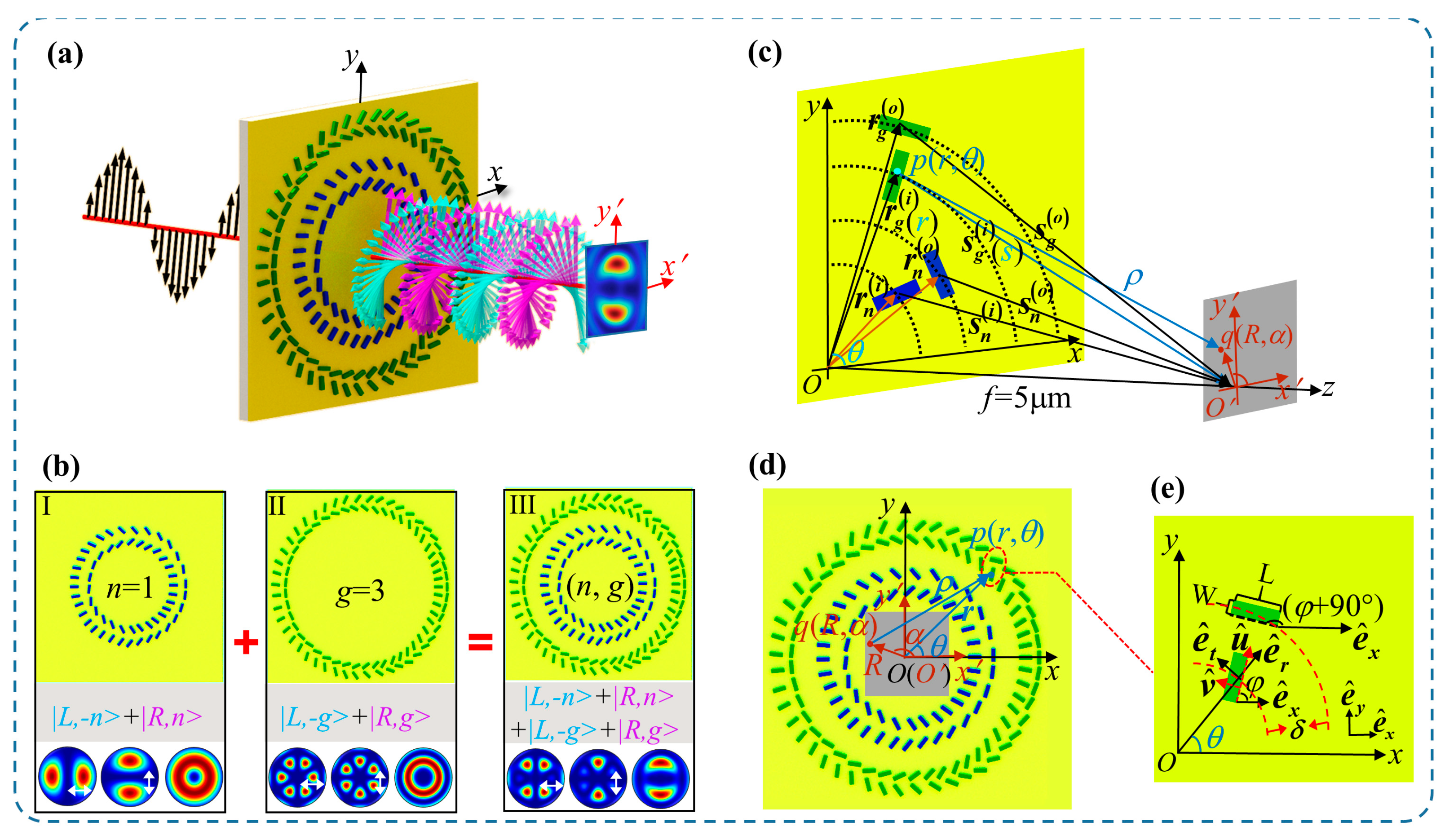
2. Basic Principles
3. Theoretical Calculation and Numerical Simulation
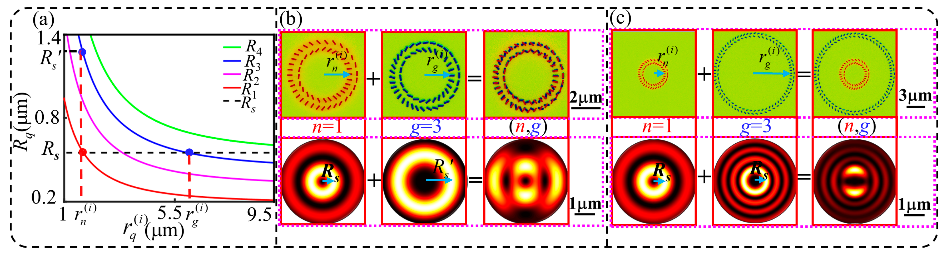
3.1. Design of the Metasurfaces
3.2. Calculation of the Superimposed Field of Tightly-Focused VBs
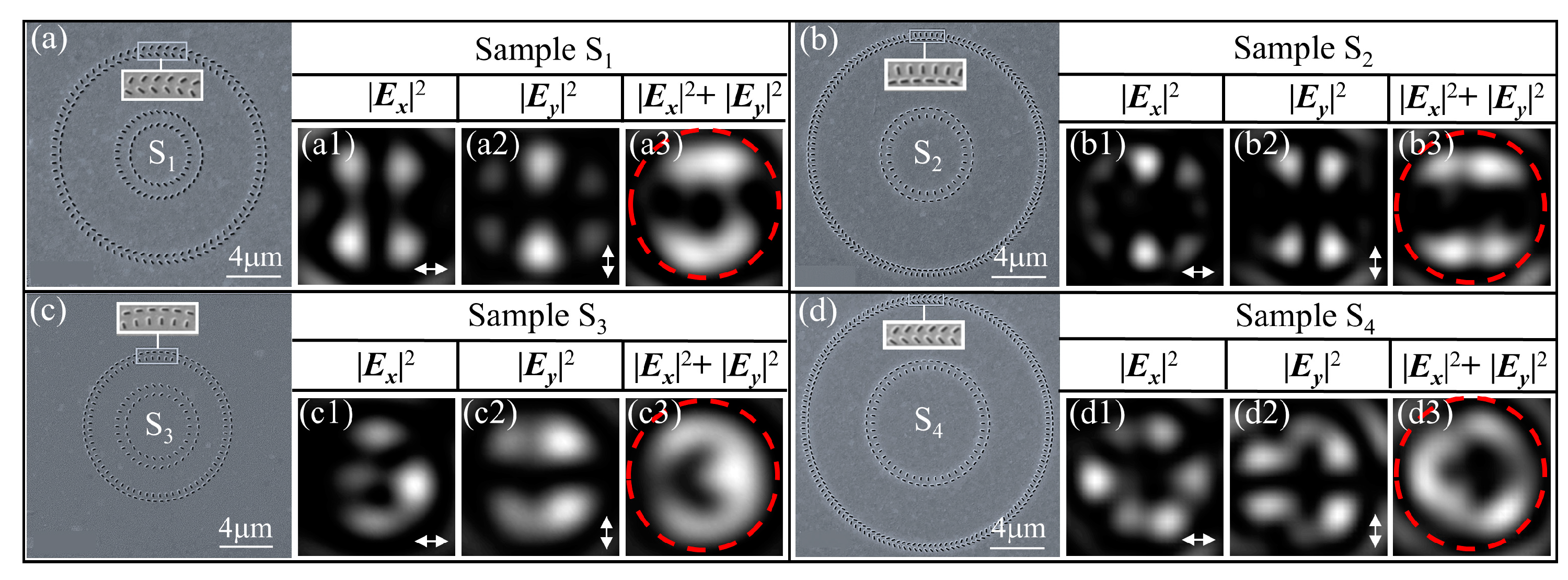
3.3. Analysis of Results
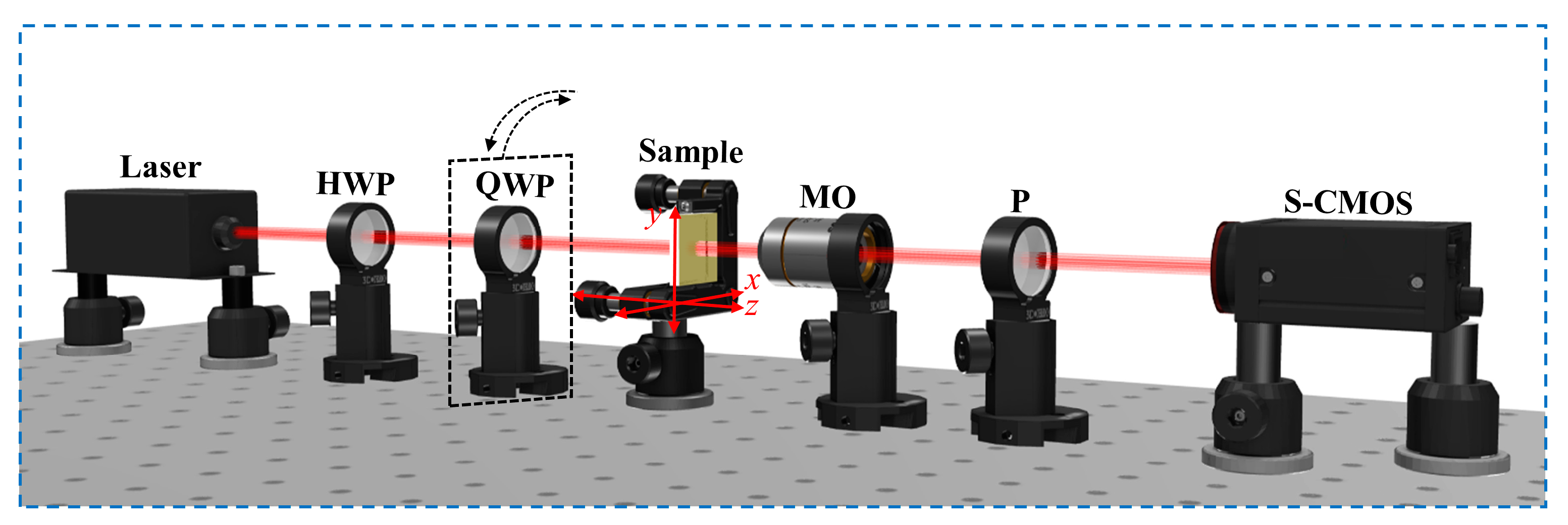
4. Experiment
5. Discussions
6. Conclusions
Author Contributions
Funding
Institutional Review Board Statement
Informed Consent Statement
Data Availability Statement
Conflicts of Interest
References
- Chen, W.T.; Zhu, A.Y.; Capasso, F. Flat optics with dispersion-engineered metasurfaces. Nat. Rev. Mater. 2020, 5, 604–620. [Google Scholar] [CrossRef]
- Ding, F.; Yang, Y.; Deshpande, R.A.; Bozhevolnyi, S.I. A review of gap-surface plasmon metasurfaces: Fundamentals and applications. Nanophotonics 2018, 7, 1129–1156. [Google Scholar] [CrossRef]
- Li, A.; Singh, S.; Sievenpiper, D. Metasurfaces and their applications. Nanophotonics 2018, 7, 989–1011. [Google Scholar] [CrossRef]
- Zang, X.; Ding, H.; Intaravanne, Y.; Chen, L.; Peng, Y.; Xie, J.; Ke, Q.; Balakin, A.V.; Shkurinov, A.P.; Chen, X.; et al. A Multi-Foci Metalens with Polarization-Rotated Focal Points. Laser Photonics Rev. 2019, 13, 1900182. [Google Scholar] [CrossRef]
- Chen, M.K.; Wu, Y.; Feng, L.; Fan, Q.; Lu, M.; Xu, T.; Tsai, D.P. Principles, Functions, and Applications of Optical Meta-Lens. Adv. Opt. Mater. 2021, 9, 2001414. [Google Scholar] [CrossRef]
- Khorasaninejad, M.; Chen, W.T.; Devlin, R.C.; Oh, J.; Zhu, A.Y.; Capasso, F. Metalenses at visible wavelengths: Diffraction-limited focusing and subwavelength resolution imaging. Science 2016, 352, 1190–1194. [Google Scholar] [CrossRef] [Green Version]
- Zhao, R.; Sain, B.; Wei, Q.; Tang, C.; Li, X.; Weiss, T.; Huang, L.; Wang, Y.; Zentgraf, T. Multichannel vectorial holographic display and encryption. Light Sci. Appl. 2018, 7, 95. [Google Scholar] [CrossRef] [Green Version]
- Ren, H.; Briere, G.; Fang, X.; Ni, P.; Sawant, R.; Héron, S.; Chenot, S.; Vézian, S.; Damilano, B.; Brändli, V.; et al. Metasurface orbital angular momentum holography. Nat. Commun. 2019, 10, 2986. [Google Scholar] [CrossRef] [Green Version]
- Kim, I.; Jang, J.; Kim, G.; Lee, J.; Badloe, T.; Mun, J.; Rho, J. Pixelated bifunctional metasurface-driven dynamic vectorial holographic color prints for photonic security platform. Nat. Commun. 2021, 12, 3614. [Google Scholar] [CrossRef]
- Ren, H.; Fang, X.; Jang, J.; Bürger, J.; Rho, J.; Maier, S.A. Complex-amplitude metasurface-based orbital angular momentum holography in momentum space. Nat. Nanotechnol. 2020, 15, 948–955. [Google Scholar] [CrossRef]
- Tseng, M.L.; Jahani, Y.; Leitis, A.; Altug, H. Dielectric Metasurfaces Enabling Advanced Optical Biosensors. ACS Photonics 2021, 8, 47–60. [Google Scholar] [CrossRef]
- Zhang, S.; Wong, C.L.; Zeng, S.; Bi, R.; Tai, K.; Dholakia, K.; Olivo, M. Metasurfaces for biomedical applications: Imaging and sensing from a nanophotonics perspective. Nanophotonics 2021, 10, 259–293. [Google Scholar] [CrossRef]
- Kim, I.; Martins, R.J.; Jang, J.; Badloe, T.; Khadir, S.; Jung, H.-Y.; Kim, H.; Kim, J.; Genevet, P.; Rho, J. Nanophotonics for light detection and ranging technology. Nat. Nanotechnol. 2021, 16, 508–524. [Google Scholar] [CrossRef] [PubMed]
- Rodrigo, D.; Tittl, A.; Ait-Bouziad, N.; John-Herpin, A.; Limaj, O.; Kelly, C.; Yoo, D.; Wittenberg, N.J.; Oh, S.-H.; Lashuel, H.A.; et al. Resolving molecule-specific information in dynamic lipid membrane processes with multi-resonant infrared metasurfaces. Nat. Commun. 2018, 9, 2160. [Google Scholar] [CrossRef] [PubMed] [Green Version]
- Flauraud, V.; Reyes, M.; Paniagua-Domínguez, R.; Kuznetsov, A.I.; Brugger, J. Silicon Nanostructures for Bright Field Full Color Prints. ACS Photonics 2017, 4, 1913–1919. [Google Scholar] [CrossRef]
- Daqiqeh Rezaei, S.; Dong, Z.; You En Chan, J.; Trisno, J.; Ng, R.J.H.; Ruan, Q.; Qiu, C.-W.; Mortensen, N.A.; Yang, J.K.W. Nanophotonic Structural Colors. ACS Photonics 2021, 8, 18–33. [Google Scholar] [CrossRef]
- Sun, S.; Zhou, Z.; Zhang, C.; Gao, Y.; Duan, Z.; Xiao, S.; Song, Q. All-Dielectric Full-Color Printing with TiO2 Metasurfaces. ACS Nano 2017, 11, 4445–4452. [Google Scholar] [CrossRef]
- Yang, W.; Xiao, S.; Song, Q.; Liu, Y.; Wu, Y.; Wang, S.; Yu, J.; Han, J.; Tsai, D.-P. All-dielectric metasurface for high-performance structural color. Nat. Commun. 2020, 11, 1864. [Google Scholar] [CrossRef] [Green Version]
- Sun, S.; Yang, K.-Y.; Wang, C.-M.; Juan, T.-K.; Chen, W.T.; Liao, C.Y.; He, Q.; Xiao, S.; Kung, W.-T.; Guo, G.-Y.; et al. High-Efficiency Broadband Anomalous Reflection by Gradient Meta-Surfaces. Nano Lett. 2012, 12, 6223–6229. [Google Scholar] [CrossRef]
- Lin, D.; Fan, P.; Hasman, E.; Brongersma, M.L. Dielectric gradient metasurface optical elements. Science 2014, 345, 298–302. [Google Scholar] [CrossRef]
- Yu, N.; Genevet, P.; Kats, M.A.; Aieta, F.; Tetienne, J.-P.; Capasso, F.; Gaburro, Z. Light Propagation with Phase Discontinuities: Generalized Laws of Reflection and Refraction. Science 2011, 334, 333–337. [Google Scholar] [CrossRef] [Green Version]
- Sun, S.; He, Q.; Xiao, S.; Xu, Q.; Li, X.; Zhou, L. Gradient-index meta-surfaces as a bridge linking propagating waves and surface waves. Nat. Mater. 2012, 11, 426–431. [Google Scholar] [CrossRef] [PubMed]
- Huang, L.; Chen, X.; Mühlenbernd, H.; Li, G.; Bai, B.; Tan, Q.; Jin, G.; Zentgraf, T.; Zhang, S. Dispersionless Phase Discontinuities for Controlling Light Propagation. Nano Lett. 2012, 12, 5750–5755. [Google Scholar] [CrossRef]
- Zaman, M.A.; Padhy, P.; Hesselink, L. Solenoidal optical forces from a plasmonic Archimedean spiral. Phys. Rev. A 2019, 100, 013857. [Google Scholar] [CrossRef]
- Tsai, W.-Y.; Huang, J.-S.; Huang, C.-B. Selective Trapping or Rotation of Isotropic Dielectric Microparticles by Optical Near Field in a Plasmonic Archimedes Spiral. Nano Lett. 2014, 14, 547–552. [Google Scholar] [CrossRef]
- Zhang, Y.; Zhang, R.; Li, X.; Ma, L.; Liu, C.; He, C.; Cheng, C. Radially polarized plasmonic vector vortex generated by a metasurface spiral in gold film. Opt. Express 2017, 25, 32150–32160. [Google Scholar] [CrossRef] [PubMed]
- Kim, M.; Lee, D.; Yang, Y.; Kim, Y.; Rho, J. Reaching the highest efficiency of spin Hall effect of light in the near-infrared using all-dielectric metasurfaces. Nat. Commun. 2022, 13, 2036. [Google Scholar] [CrossRef]
- Luo, W.; Sun, S.; Xu, H.-X.; He, Q.; Zhou, L. Transmissive Ultrathin Pancharatnam-Berry Metasurfaces with nearly 100% Efficiency. Phys. Rev. A 2017, 7, 044033. [Google Scholar] [CrossRef]
- Yuan, Y.; Zhang, K.; Ratni, B.; Song, Q.; Ding, X.; Wu, Q.; Burokur, S.N.; Genevet, P. Independent phase modulation for quadruplex polarization channels enabled by chirality-assisted geometric-phase metasurfaces. Nat. Commun. 2020, 11, 4186. [Google Scholar] [CrossRef]
- Xiang, Z.; Shen, Z.; Shen, Y. Quasi-perfect vortices generated by Pancharatnam-Berry phase metasurfaces for optical spanners and OAM communication. Sci. Rep. 2022, 12, 1053. [Google Scholar] [CrossRef]
- Ni, J.; Huang, C.; Zhou, L.-M.; Gu, M.; Song, Q.; Kivshar, Y.; Qiu, C.-W. Multidimensional phase singularities in nanophotonics. Science 2021, 374, 418. [Google Scholar] [CrossRef] [PubMed]
- Forbes, A.; de Oliveira, M.; Dennis, M.R. Structured light. Nat. Photonics 2021, 15, 253–262. [Google Scholar] [CrossRef]
- Xie, X.; Chen, Y.; Yang, K.; Zhou, J. Harnessing the Point-Spread Function for High-Resolution Far-Field Optical Microscopy. Phys. Rev. Lett. 2014, 113, 263901. [Google Scholar] [CrossRef]
- Roxworthy, B.J.; Toussaint, K.C. Optical trapping with pi-phase cylindrical vector beams. New J. Phys. 2010, 12, 073012. [Google Scholar] [CrossRef]
- Yuanjie, Y.; Yuxuan, R.; Mingzhou, C.; Yoshihiko, A.; Carmelo, R.-G. Optical trapping with structured light: A review. Adv. Photonics 2021, 3, 034001. [Google Scholar] [CrossRef]
- He, C.; He, H.; Chang, J.; Chen, B.; Ma, H.; Booth, M.J. Polarisation optics for biomedical and clinical applications: A review. Light Sci. Appl. 2021, 10, 194. [Google Scholar] [CrossRef]
- Sit, A.; Bouchard, F.; Fickler, R.; Gagnon-Bischoff, J.; Larocque, H.; Heshami, K.; Elser, D.; Peuntinger, C.; Günthner, K.; Heim, B.; et al. High-dimensional intracity quantum cryptography with structured photons. Optica 2017, 4, 1006–1010. [Google Scholar] [CrossRef] [Green Version]
- Rosales-Guzmán, C.; Bhebhe, N.; Forbes, A. Simultaneous generation of multiple vector beams on a single SLM. Opt. Express 2017, 25, 25697–25706. [Google Scholar] [CrossRef]
- Parigi, V.; D’Ambrosio, V.; Arnold, C.; Marrucci, L.; Sciarrino, F.; Laurat, J. Storage and retrieval of vector beams of light in a multiple-degree-of-freedom quantum memory. Nat. Commun. 2015, 6, 7706. [Google Scholar] [CrossRef] [Green Version]
- Cardano, F.; Massa, F.; Qassim, H.; Karimi, E.; Slussarenko, S.; Paparo, D.; de Lisio, C.; Sciarrino, F.; Santamato, E.; Boyd, R.W.; et al. Quantum walks and wavepacket dynamics on a lattice with twisted photons. Sci. Adv. 2015, 1, e1500087. [Google Scholar] [CrossRef] [Green Version]
- Graham, T.M.; Bernstein, H.J.; Wei, T.-C.; Junge, M.; Kwiat, P.G. Superdense teleportation using hyperentangled photons. Nat. Commun. 2015, 6, 7185. [Google Scholar] [CrossRef] [PubMed] [Green Version]
- Ndagano, B.; Perez-Garcia, B.; Roux, F.S.; McLaren, M.; Rosales-Guzman, C.; Zhang, Y.; Mouane, O.; Hernandez-Aranda, R.I.; Konrad, T.; Forbes, A. Characterizing quantum channels with non-separable states of classical light. Nat. Phys. 2017, 13, 397–402. [Google Scholar] [CrossRef]
- Toninelli, E.; Ndagano, B.; Vallés, A.; Sephton, B.; Nape, I.; Ambrosio, A.; Capasso, F.; Padgett, M.J.; Forbes, A. Concepts in quantum state tomography and classical implementation with intense light: A tutorial. Adv. Opt. Photonics 2019, 11, 67–134. [Google Scholar] [CrossRef] [Green Version]
- Yan, H.; Li, S.; Xie, Z.; Zheng, X.; Zhang, H.; Zhou, B. Design of PANDA ring-core fiber with 10 polarization-maintaining modes. Photonics Res. 2017, 5, 1–5. [Google Scholar] [CrossRef]
- Vasilyeu, R.; Dudley, A.; Khilo, N.; Forbes, A. Generating superpositions of higher–order Bessel beams. Opt. Express 2009, 17, 23389–23395. [Google Scholar] [CrossRef] [PubMed] [Green Version]
- Naidoo, D.; Roux, F.S.; Dudley, A.; Litvin, I.; Piccirillo, B.; Marrucci, L.; Forbes, A. Controlled generation of higher-order Poincaré sphere beams from a laser. Nat. Photonics 2016, 10, 327–332. [Google Scholar] [CrossRef] [Green Version]
- Wan, H.; Wang, J.; Zhang, Z.; Cai, Y.; Sun, B.; Zhang, L. High efficiency mode-locked, cylindrical vector beam fiber laser based on a mode selective coupler. Opt. Express 2017, 25, 11444–11451. [Google Scholar] [CrossRef]
- Yan, H.; Zhang, E.; Zhao, B.; Duan, K. Free-space propagation of guided optical vortices excited in an annular core fiber. Opt. Express 2012, 20, 17904–17915. [Google Scholar] [CrossRef]
- Li, S.; Wang, J. Multi-Orbital-Angular-Momentum Multi-Ring Fiber for High-Density Space-Division Multiplexing. IEEE Photonics J. 2013, 5, 7101007. [Google Scholar] [CrossRef]
- García-García, J.; Rickenstorff-Parrao, C.; Ramos-García, R.; Arrizón, V.; Ostrovsky, A.S. Simple technique for generating the perfect optical vortex. Opt. Lett. 2014, 39, 5305–5308. [Google Scholar] [CrossRef]
- Ostrovsky, A.S.; Rickenstorff-Parrao, C.; Arrizón, V. Generation of the “perfect” optical vortex using a liquid-crystal spatial light modulator. Opt. Lett. 2013, 38, 534–536. [Google Scholar] [CrossRef]
- Vaity, P.; Rusch, L. Perfect vortex beam: Fourier transformation of a Bessel beam. Opt. Lett. 2015, 40, 597–600. [Google Scholar] [CrossRef]
- Dong, M.; Yang, Z.; Chao, Z.; Hua, L.; Cong, W.; Han, Z.; Wending, Z.; Ting, M.; Jianlin, Z. Generation of polarization and phase singular beams in fibers and fiber lasers. Adv. Photonics 2021, 3, 014002. [Google Scholar] [CrossRef]
- Li, P.; Zhang, Y.; Liu, S.; Ma, C.; Han, L.; Cheng, H.; Zhao, J. Generation of perfect vectorial vortex beams. Opt. Lett. 2016, 41, 2205–2208. [Google Scholar] [CrossRef]
- Fu, S.; Gao, C.; Wang, T.; Zhang, S.; Zhai, Y. Simultaneous generation of multiple perfect polarization vortices with selective spatial states in various diffraction orders. Opt. Lett. 2016, 41, 5454–5457. [Google Scholar] [CrossRef] [PubMed]
- Li, D.; Chang, C.; Nie, S.; Feng, S.; Ma, J.; Yuan, C. Generation of elliptic perfect optical vortex and elliptic perfect vector beam by modulating the dynamic and geometric phase. Appl. Phys. Lett. 2018, 113, 121101. [Google Scholar] [CrossRef]
- Liu, Y.; Ke, Y.; Zhou, J.; Liu, Y.; Luo, H.; Wen, S.; Fan, D. Generation of perfect vortex and vector beams based on Pancharatnam-Berry phase elements. Sci. Rep. 2017, 7, 44096. [Google Scholar] [CrossRef] [Green Version]
- Liu, Z.; Liu, Y.; Ke, Y.; Liu, Y.; Shu, W.; Luo, H.; Wen, S. Generation of arbitrary vector vortex beams on hybrid-order Poincaré sphere. Photonics Res. 2017, 5, 15–21. [Google Scholar] [CrossRef] [Green Version]
- Bao, Y.; Ni, J.; Qiu, C.-W. A Minimalist Single-Layer Metasurface for Arbitrary and Full Control of Vector Vortex Beams. Adv. Mater. 2020, 32, 1905659. [Google Scholar] [CrossRef]
- Wang, E.; Shi, L.; Niu, J.; Hua, Y.; Li, H.; Zhu, X.; Xie, C.; Ye, T. Multichannel Spatially Nonhomogeneous Focused Vector Vortex Beams for Quantum Experiments. Adv. Opt. Mater. 2019, 7, 1801415. [Google Scholar] [CrossRef]
- Zhang, Y.-Q.; Zeng, X.-Y.; Zhang, R.-R.; Zhan, Z.-J.; Li, X.; Ma, L.; Liu, C.-X.; He, C.-W.; Cheng, C.-F. Generation of a plasmonic radially polarized vector beam with linearly polarized illumination. Opt. Lett. 2018, 43, 4208–4211. [Google Scholar] [CrossRef]
- Yue, F.; Wen, D.; Xin, J.; Gerardot, B.D.; Li, J.; Chen, X. Vector Vortex Beam Generation with a Single Plasmonic Metasurface. ACS Photonics 2016, 3, 1558–1563. [Google Scholar] [CrossRef]
- Liu, M.; Huo, P.; Zhu, W.; Zhang, C.; Zhang, S.; Song, M.; Zhang, S.; Zhou, Q.; Chen, L.; Lezec, H.J.; et al. Broadband generation of perfect Poincaré beams via dielectric spin-multiplexed metasurface. Nat. Commun. 2021, 12, 2230. [Google Scholar] [CrossRef] [PubMed]
- Yang, Q.; Xie, Z.; Zhang, M.; Ouyang, X.; Xu, Y.; Cao, Y.; Wang, S.; Zhu, L.; Li, X. Ultra-secure optical encryption based on tightly focused perfect optical vortex beams. Nanophotonics 2022, 11, 1063–1070. [Google Scholar] [CrossRef]
- Shao, W.; Huang, S.; Liu, X.; Chen, M. Free-space optical communication with perfect optical vortex beams multiplexing. Opt. Commun. 2018, 427, 545–550. [Google Scholar] [CrossRef]
- Wang, W.; Wang, P.; Pang, W.; Pan, Y.; Nie, Y.; Guo, L. Evolution Properties and Spatial-Mode UWOC Performances of the Perfect Vortex Beam Subject to Oceanic Turbulence. IEEE Trans. Commun. 2021, 69, 7647–7658. [Google Scholar] [CrossRef]
- Chen, M.; Mazilu, M.; Arita, Y.; Wright, E.M.; Dholakia, K. Dynamics of microparticles trapped in a perfect vortex beam. Opt. Lett. 2013, 38, 4919–4922. [Google Scholar] [CrossRef]
- Han, L.; Liu, S.; Li, P.; Zhang, Y.; Cheng, H.; Zhao, J. Catalystlike effect of orbital angular momentum on the conversion of transverse to three-dimensional spin states within tightly focused radially polarized beams. Phys. Rev. A 2018, 97, 053802. [Google Scholar] [CrossRef]
- Guo, X.; Li, P.; Zhong, J.; Liu, S.; Wei, B.; Zhu, W.; Qi, S.; Cheng, H.; Zhao, J. Tying Polarization-Switchable Optical Vortex Knots and Links via Holographic All-Dielectric Metasurfaces. Laser Photonics Rev. 2020, 14, 1900366. [Google Scholar] [CrossRef]
- Zuo, R.; Liu, W.; Cheng, H.; Chen, S.; Tian, J. Breaking the Diffraction Limit with Radially Polarized Light Based on Dielectric Metalenses. Adv. Opt. Mater. 2018, 6, 1800795. [Google Scholar] [CrossRef]
- Li, Y.; Cao, L.; Wen, Z.; Qin, C.; Yang, J.; Zhang, Z.; Liang, G.; Shang, Z.; Zhang, K.; Zhang, S.; et al. Broadband quarter-wave birefringent meta-mirrors for generating sub-diffraction vector fields. Opt. Lett. 2019, 44, 110–113. [Google Scholar] [CrossRef]
- Lin, J.; Mueller, J.P.B.; Wang, Q.; Yuan, G.; Antoniou, N.; Yuan, X.-C.; Capasso, F. Polarization-Controlled Tunable Directional Coupling of Surface Plasmon Polaritons. Science 2013, 340, 331–334. [Google Scholar] [CrossRef] [PubMed]
- Zhang, R.; Zhang, Y.; Ma, L.; Zeng, X.; Li, X.; Zhan, Z.; Ren, X.; He, C.; Liu, C.; Cheng, C. Nanoscale optical lattices of arbitrary orders manipulated by plasmonic metasurfaces combining geometrical and dynamic phases. Nanoscale 2019, 11, 14024–14031. [Google Scholar] [CrossRef]
- Zeng, X.; Zhang, Y.; Gu, M.; Zhan, Z.; Zhang, R.; Zhang, Y.; Sun, R.; He, C.; Liu, C.; Cheng, C. Arbitrary manipulations of focused higher-order Poincaré beams by a Fresnel zone metasurface with alternate binary geometric and propagation phases. Photonics Res. 2022, 10, 1117–1126. [Google Scholar] [CrossRef]
- Teperik, T.V.; Archambault, A.; Marquier, F.; Greffet, J.J. Huygens-Fresnel principle for surface plasmons. Opt. Express 2009, 17, 17483–17490. [Google Scholar] [CrossRef] [Green Version]
- RefractiveIndex.INFO-Refractive Index Database. Available online: https://refractiveindex.info/ (accessed on 11 March 2023).
- Babar, S.; Weaver, J.H. Optical constants of Cu, Ag, and Au revisited. Appl. Opt. 2015, 54, 477–481. [Google Scholar] [CrossRef]
- Malitson, I.H. Interspecimen Comparison of the Refractive Index of Fused Silica*,†. J. Opt. Soc. Am. 1965, 55, 1205–1209. [Google Scholar] [CrossRef]
- Zhan, Q. Cylindrical vector beams: From mathematical concepts to applications. Adv. Opt. Photonics 2009, 1, 1–57. [Google Scholar] [CrossRef]
- Lu, T.H.; Huang, T.D.; Wang, J.G.; Wang, L.W.; Alfano, R.R. Generation of flower high-order Poincaré sphere laser beams from a spatial light modulator. Sci. Rep. 2016, 6, 39657. [Google Scholar] [CrossRef] [PubMed] [Green Version]
- Milione, G.; Evans, S.; Nolan, D.A.; Alfano, R.R. Higher Order Pancharatnam-Berry Phase and the Angular Momentum of Light. Phys. Rev. Lett. 2012, 108, 190401. [Google Scholar] [CrossRef] [Green Version]


| Sample | S1 | S2 | S3 | S4 |
|---|---|---|---|---|
| (n, g) | (1, 3) | (2, 4) | (1, 2) | (2, 3) |
| Rs | 0.5458 | 0.63 | 0.432 | 0.4844 |
| 1.807 | 2.7983 | 2.3775 | 4.1119 | |
| 2.587 | 3.3993 | 3.041 | 4.5939 | |
| 6.048 | 8.0784 | 5.0731 | 8.978 | |
| 6.448 | 8.4482 | 5.5085 | 9.3415 |
Disclaimer/Publisher’s Note: The statements, opinions and data contained in all publications are solely those of the individual author(s) and contributor(s) and not of MDPI and/or the editor(s). MDPI and/or the editor(s) disclaim responsibility for any injury to people or property resulting from any ideas, methods, instructions or products referred to in the content. |
© 2023 by the authors. Licensee MDPI, Basel, Switzerland. This article is an open access article distributed under the terms and conditions of the Creative Commons Attribution (CC BY) license (https://creativecommons.org/licenses/by/4.0/).
Share and Cite
Li, L.; Zeng, X.; Gu, M.; Zhang, Y.; Sun, R.; Zhang, Z.; Cui, G.; Zhou, Y.; Cheng, C.; Liu, C. Plasmonic Metasurfaces for Superposition of Profile-Tunable Tightly Focused Vector Beams and Generation of the Structured Light. Photonics 2023, 10, 317. https://doi.org/10.3390/photonics10030317
Li L, Zeng X, Gu M, Zhang Y, Sun R, Zhang Z, Cui G, Zhou Y, Cheng C, Liu C. Plasmonic Metasurfaces for Superposition of Profile-Tunable Tightly Focused Vector Beams and Generation of the Structured Light. Photonics. 2023; 10(3):317. https://doi.org/10.3390/photonics10030317
Chicago/Turabian StyleLi, Lianmeng, Xiangyu Zeng, Manna Gu, Yuqin Zhang, Rui Sun, Ziheng Zhang, Guosen Cui, Yuxiang Zhou, Chuanfu Cheng, and Chunxiang Liu. 2023. "Plasmonic Metasurfaces for Superposition of Profile-Tunable Tightly Focused Vector Beams and Generation of the Structured Light" Photonics 10, no. 3: 317. https://doi.org/10.3390/photonics10030317