1. Introduction
Since the rise of modern short- to mid-range communication systems, innovation and advancements in this field (mobile services, radar, Internet-of-Things (IoT) and optical communication systems) heavily rely on the availability of high-speed transceivers. The total amount of data transferred increased exponentially to 122 exabyte per month by 2017, while it was expected to reach over 396 exabyte per month by 2022 [
1]. Although this development calls for even faster networking equipment, the energy and cost efficiency of the devices also starts to be equally important. Low energy efficiency leads to several problems on all architectural levels, from thermal management (when dealing with high integration), to higher operating costs, to the toll on the environment. Vertical-Cavity Surface-Emitting Laser (VCSEL) diodes [
2,
3,
4,
5] are known to be much more cost and energy-efficient at converting electrical signals into optical signals than alternative optical sources or modulators, such as Mach-Zehnder-Modulator (MZMs) or Electro-Absorption Modulated Laser (EMLs). However, the gain in power efficiency for VCSEL-based transmitter systems is much smaller than expected as the VCSEL-driver dominates the overall power budget.
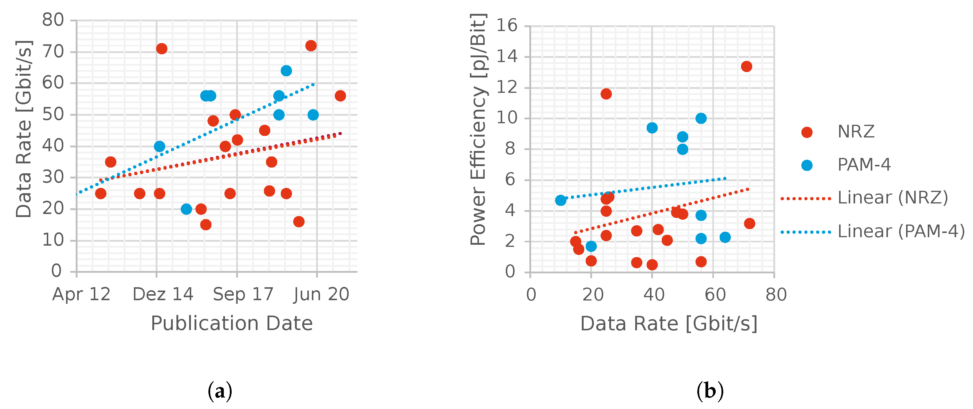
The obtained data rates of recently published VCSEL transmit systems are plotted in
Figure 1a. Although the average data rate has increased over the years, both for Non-Return to Zero (NRZ) and Pulse Amplitude Modulation (PAM)-modulated systems, no significant improvement of the State-of-the-Art (SOTA) data rate has been achieved since the publishing of [
6] at 71 Gbit/s in 2014. It should be noted that the link with the highest published data rate [
7] still uses NRZ modulation even though the PAM-4 modulation scheme should ideally increase the data rate by 2x when considering the same system bandwidth. Although 100 Gbit/s optical Multi-Mode Fiber (MMF) transmission standardization is finalized [
8] with companies claiming products capable of this performance [
9], published VCSEL transmitter systems using PAM-4 signaling only reached data rates of 60 Gbit/s such as [
10,
11,
12]. As can be seen in
Figure 1b, the most efficient VCSEL transmitters are also still using NRZ modulation. Although VCSELs are very energy-efficient, they suffer from limited bandwidth, a frequency response with current-dependent resonant behavior leading to overshoots as well as non-linear rise-and-fall times, which significantly impairs the Bit-Error Rate (BER) using PAM-4 modulation schemes. This paper aims to demonstrate PAM-4-based equalization techniques that can easily be implemented into Digital-to-Analog Converter (DAC)-based transmitters, enabling transmission at over 100 Gbit/s reaching efficiencies common for copper-based transmitter systems. This scheme could also easily be extended to be used with PAM-6 or even PAM-8 modulation.
2. Non-Linear VCSEL Behavior
All directly modulated LASERs (and therefore also VCSELs) exhibit non-linear behavior in their frequency response when varying the operation current, which happens with every change of the data symbol i.e., changing the optical power level.
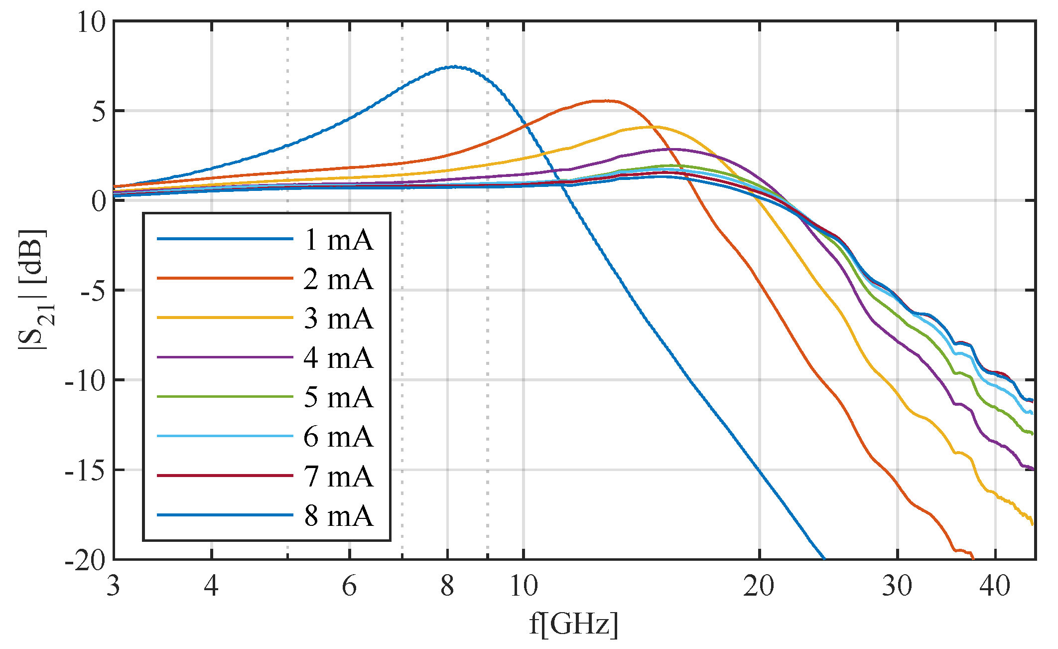
Figure 2 shows the measured frequency response of a VCSEL [
2] for different bias currents. It is evident that the VCSEL exhibits biasing-dependent resonance frequency shifts and non-linear bandwidth reduction that influences its frequency response and data transmission.
At low currents, the resonance is very distinct, causing strong Inter Symbol Interference (ISI). To obtain a flatter frequency response and avoid strong resonances, VCSELs are usually biased above 3
. For higher currents, the resonances become increasingly less pronounced. However, larger VCSEL bias currents inherently cause self-heating effects in turn limiting the VCSEL’s bandwidth [
3] or (when surpassing operating thresholds) damaging the device. It is important to note that the measurements performed for
Figure 2 were executed at a constant bias current (so in a high self-heating state). In reality the VCSEL might exhibit such high currents only for very short duration, meaning that the VCSEL does not experience self-heating effects as severely due to its dynamic signaling. Because of this, the VCSEL can reach higher bandwidths than the Alternating Current (AC) measurements reveal.
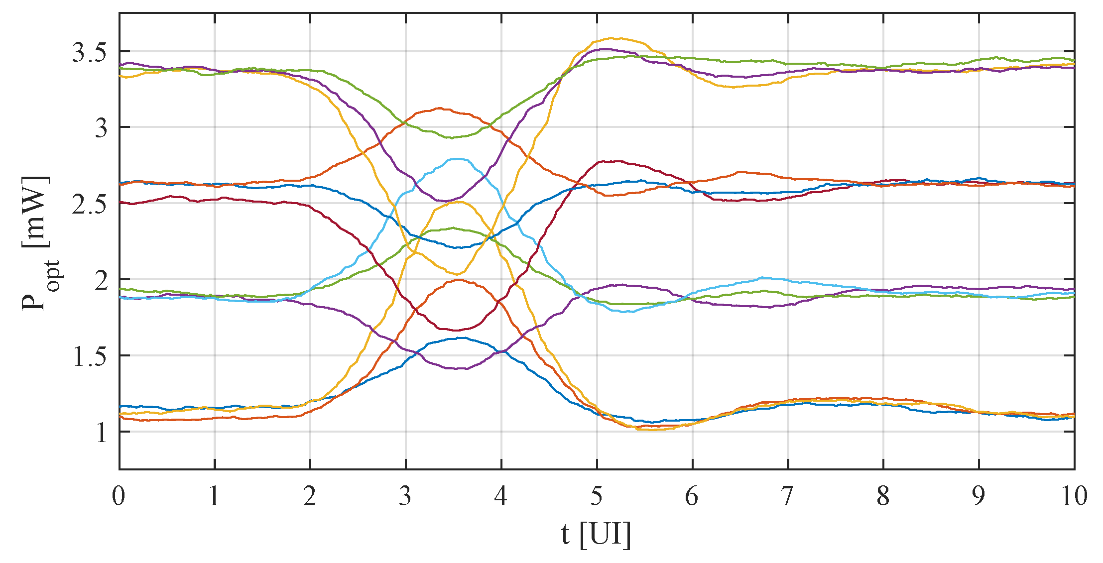
Because the AC-response measurement is somewhat limited for explaining VCSEL behavior, the so-called pulse response of a VCSEL is shown in
Figure 3. The pulse response is very similar to an impulse response, the only difference is that 1 Unit Interval (UI) wide pulses are used. A PAM-4 modulated signal has 16 different possible data transition combinations for two consecutive data sets, of which four do not cause a modulation level change. Thus, these four Direct Current (DC) cases are omitted leaving 12 different data transitions. Please note that a different VCSEL was used for AC and pulse response measurement due to test setup and assembly. It becomes evident from
Figure 3 that the VCSEL does not have sufficient bandwidth to transmit 56
as the pulses are not reaching the DC values during the transition. Moreover, the data-dependent relaxation oscillations (different per output level) are clearly visible, contributing to the ISI and BER problem. The oscillations vary both in frequency and amplitude. This means that commonly used Finite Impulse Response (FIR)/Feed-Forward Equalizer (FFE) filtering is not effective for VCSEL equalization, since the filter operates in a linear fashion such that the coefficients can only be optimized for one of the responses, not all of them.
Figure 3 also shows that the top eye will be more shifted to the left (so earlier in time) and the bottom eye more shifted to the right (so later in time) than the middle eye. This effect, called skewing, is due to the asymmetric rise-and-fall times of the VCSEL (originating from current-dependent bandwidth) and severely increases the BER of a transceiver system. It can only be prevented by non-linear filtering (like Volterra or the one proposed in this paper) or by having a specialized receiver with independent slicing times for all three PAM-4 eyes.
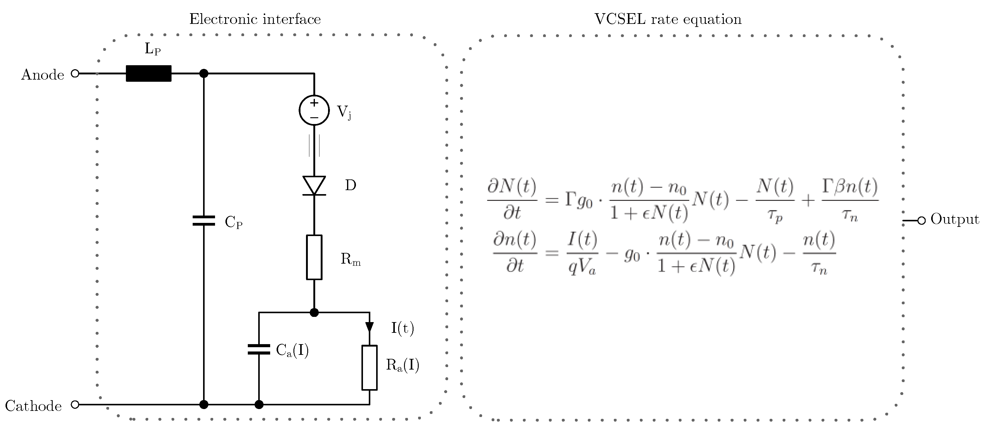
To acquire a deeper understanding of VCSEL behavior, we introduce an accurate electro-optical VCSEL model [
13]. The model used is shown in
Figure 4, where the discrete components of the electronic interface are summarized in
Table 1.
The electronic interface consists of linear, passive components, mainly modelling parasitic (pad) capacitances, inductances, non-linear diode behavior as well as the non-linear active area impedance of the LASER. The equivalent current through the active area serves as an input for the rate equations. The rate equations can be used to describe the behavior of the LASER (edge emitting and VCSEL). As it is a set of differential equations, they describe the derivation of the carrier density and the photon density . Solving the rate equations enables the estimation of the photon density, which is proportional to the optical output power. Since the current through the active area is a coefficient of the differential equation, the VCSEL exhibits non-linear behavior when the current is modulated.
The parameters are extracted by fitting model behavior to measurement data. One of the formulas used is given in Equation (
1), with
being the resonant frequency,
I being the VCSEL operating current and
being the threshold current of the VCSEL.
When trying to increase the data rate of a VCSEL-based transmission system, two approaches are possible: One either increases the baud rate, which is only possible if the bandwidth of the components is also increased. Knowing that the bandwidth of the VCSEL
is proportional to the resonance frequency
, it is only possible by designing the VCSEL in a way so the rate equation parameter
B (with the unit
[
14]) is increased, which in turn would mean that the difference in resonance frequencies
also has to increase. The other possibility is to switch from lower order modulation (like NRZ) to higher-order (like PAM-4 or PAM-8), which comes at the drawback of needing larger signal amplitudes for similar error rates. This is only possible by increasing the modulation current amplitude
, which in turn also increases
. Hence, specialized filtering for non-linear VCSEL behavior becomes increasingly important and is discussed in the following chapter.
3. Equalization Schemes
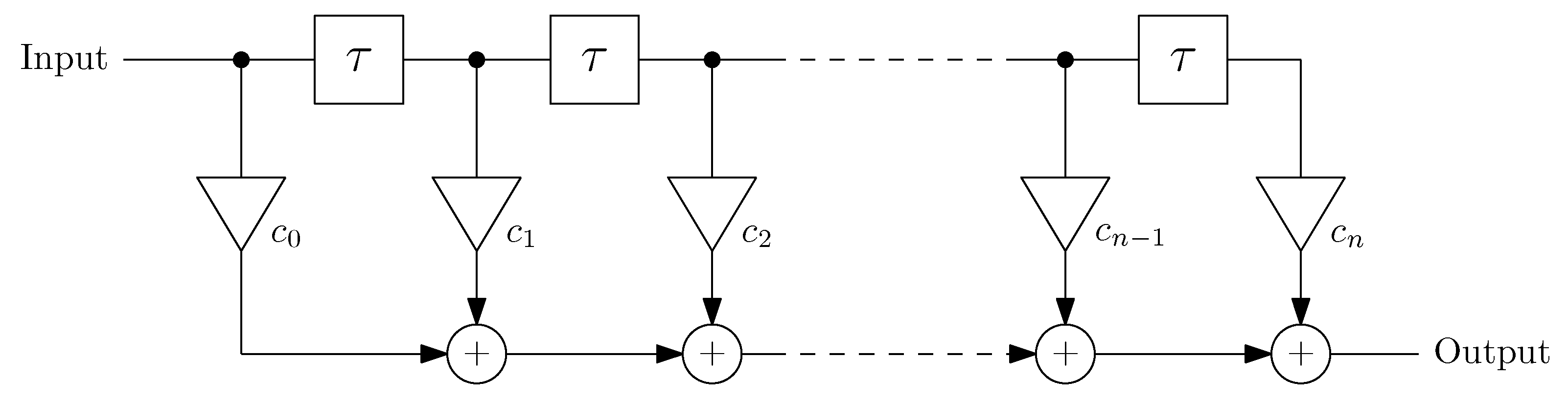
The most common linear equalization filter structure used in transmitters is the Feed-Forward Equalizer, as shown in
Figure 5. It is basically an FIR filter and works by shaping the pulse response in such a way that, in the optimal case, all pre- and post-cursors are reduced to zero, eliminating all ISI.
FFEs are very popular because of the simple and wide range of implementation architectures. The delay elements can be implemented either with synchronously clocked flip-flops, transmission lines or by analog delay elements. The summing and scaling of coefficients can be implemented by parallel connection of scaled switched current sources either before or inside the final driver. Alternatively, the filter functions can be realized in the digital domain (as an FIR either through an equivalent circuit or a simple Lookup Table (LUT)) which is then followed by a DAC-driver.
As previously discussed, FFEs are not able to filter the relaxation oscillations for all biasing and input data conditions. It was demonstrated that 112 Gbit/s PAM-4 VCSEL data transmission is possible with the use of a Volterra non-linear equalizer [
15,
16]. However, the implementation of a Volterra filter requires a power-hungry digital signal processor and cannot easily be implemented in the output driver, as would be the case with an FFE. A much more efficient technique is to dynamically adapt FFE coefficients based on the input data. Adaptive, UI-based FFE pre-emphasis was already implemented for NRZ-modulated signaling [
17,
18,
19]. These filters are made adaptive by switching the tap coefficients based on current and subsequent NRZ digital values. This is simple as only two code levels have to be considered. It is debatable though if these filter structures are really necessary for NRZ transmission, since an asymmetric data eye is not a problem as long as the BER is sufficiently low. On the contrary, for higher PAM modulation formats, equalization becomes essentially mandatory. The eye amplitude becomes a fraction of the full scale signal, overshoots can decrease the size of adjacent eyes and asymmetric rise-and-fall times have a much more severe effect.
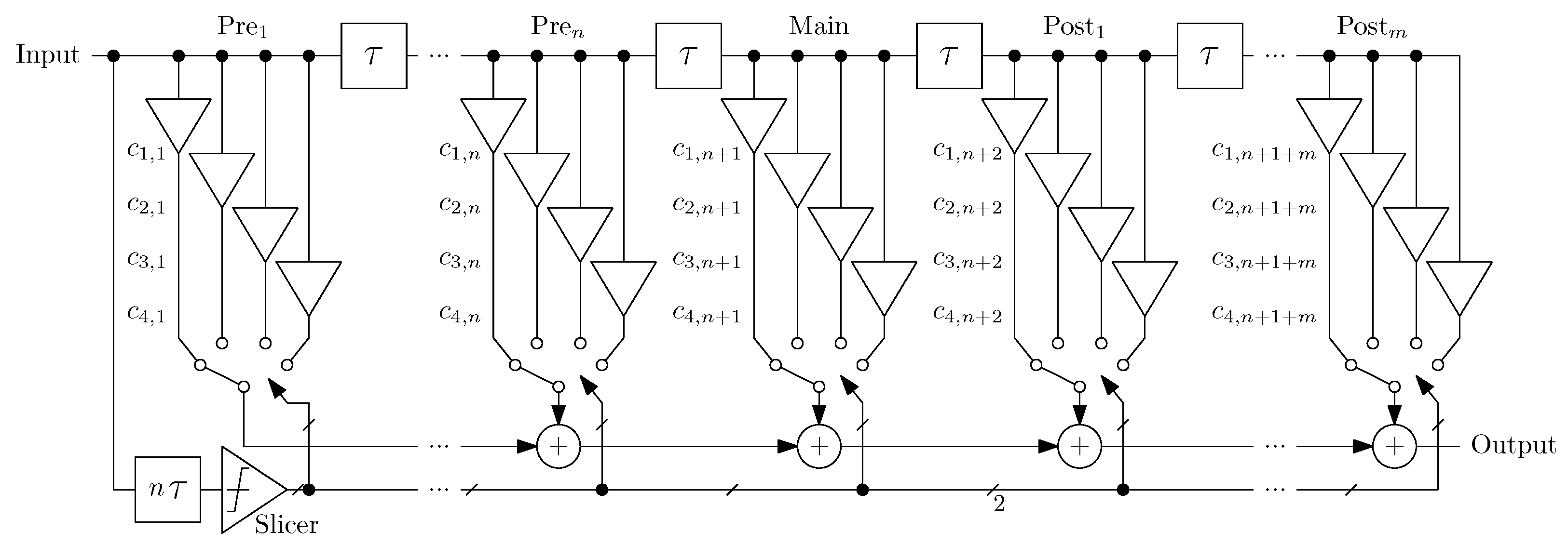
A proposal for an adaptive PAM-4 FFE [
20] is shown in
Figure 6. It works just like a linear FFE, but the actual coefficients
…
are selected depending on the state of the main tap 0, 1, 2 or 3 (00b,…,11b).
As can be seen in
Figure 3, the resulting relaxation oscillation amplitude and frequency differs for the four PAM levels. The oscillation frequency ranges from 11
for level 0 to 20
for level 3 (as a result of the bias dependent transfer function shown in
Figure 2). The main tap is used to decide on one set of coefficients, as it directly correlates with the operating current, therefore defining the oscillation behavior of the VCSEL. This equalizer design could be incorporated into standard Current-Mode Logic (CML) FFE implementations as in [
11], or as a digital adaptive FIR filter followed by a baud rate current-steering DAC with an extra VCSEL bias current source.
As explained in
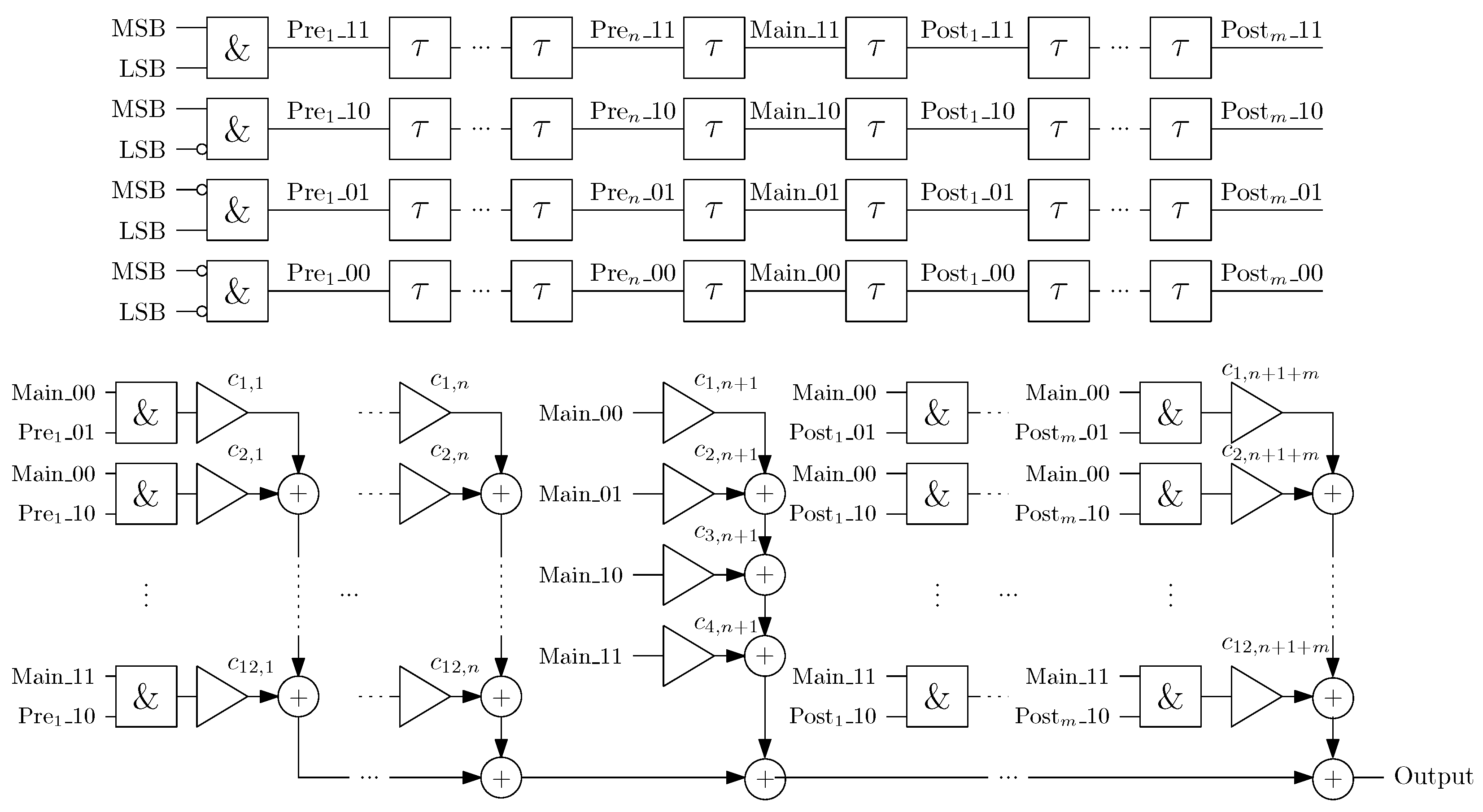
Section 2, the VCSEL shows different relaxation oscillation frequencies for all 12 possible pulse responses, so linear scaling of the coefficients is expected to improve the BER but leave significant performance boost unused. The digital sample-based topology [
20] shown in
Figure 7 uses its own set of coefficients for every possible set of pulse responses.
Each of the four possible combinations of MSB and LSB are split into four lanes of UI-based delay chains. For every tap, only one state within the chains (i.e., Pre_11,…, Pre_00) is logically true. When the state of the main tap is different from one of the other taps, an edge is detected and the corresponding FFE coefficient is added. This topology offers several advantages. First, each of the 12 pulse response combinations can be optimized (almost) independently. They are not totally independent because the height of the peak is dependent on the Pre and Post tap coefficients of the level of the peak. Second, the proposed architecture avoids multipliers which are expensive in terms of hardware and delay. Since only one of the tap states is valid, all additions of one tap can be replaced by 16 entries of a LUT. Alternatively, the proposed filter is fully realized by a LUT using 24 inputs (4 states times 6 taps) resulting in (i.e., 4096) LUT entries. Because of the complexity of the filter, a digital implementation is more energy-efficient than the analog counterpart. Using a CML approach, the adders would yield a large number of differential pairs in parallel creating an unrealistically high load. Finally, due to the digital nature of the proposed filter, this topology can also easily be extended to a larger amount of taps (at the added cost of complexity in the digital domain and hence larger power draw) as well as to handling PAM-6, PAM-8 or higher modulation formats.
4. Training Sequence
To determine linear FFE tap coefficients, the array-based method described in [
21] is used. An example for a six-tap FFE is given in Equation (
2). Here,
denote the pre-, main- and post-cursors of the pulse response. The solution of the equation yields the tap coefficients
(with
being the main tap filter coefficient).
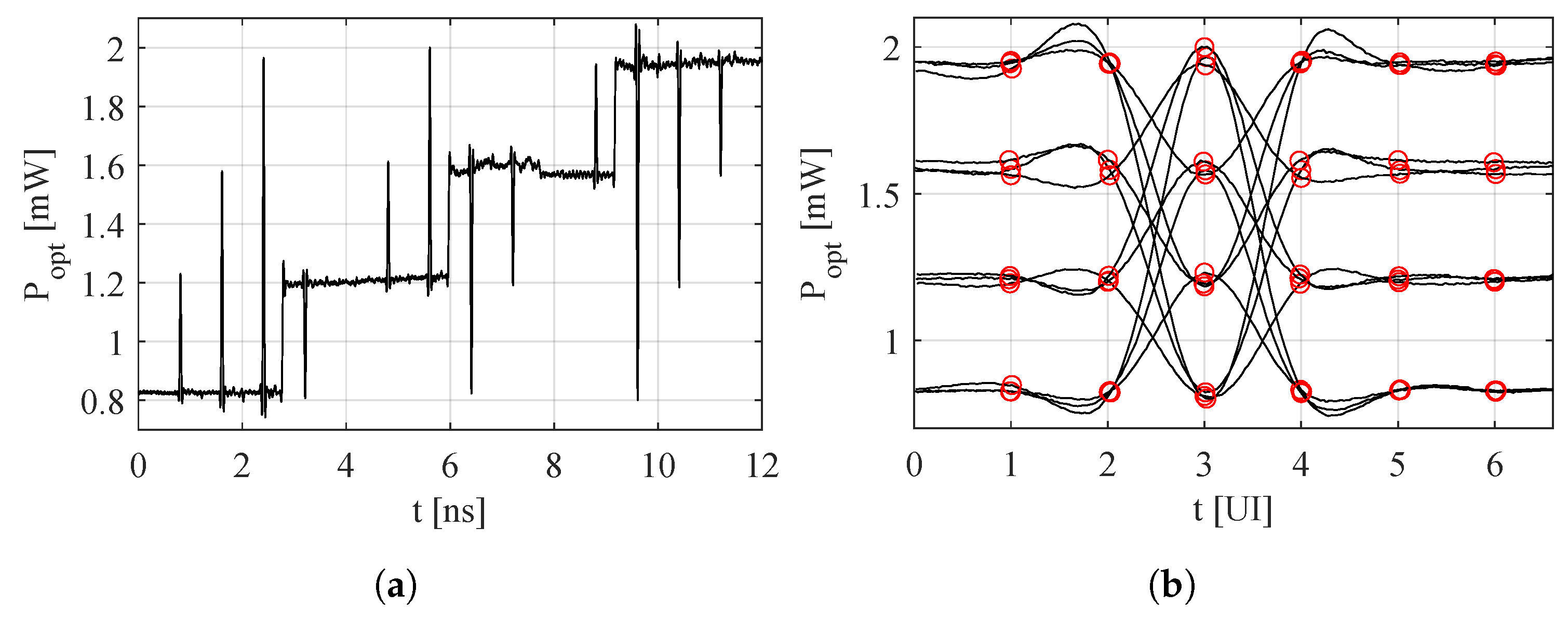
For the proposed digitally tunable FFEs a training sequence, shown in
Figure 8a, is proposed. It contains all 12 possible pulse responses. The aforementioned matrix method can then be used to calculate coefficients for every response. Since the VCSEL is not linear, this method does not yield perfect results for the first iteration. To obtain more accurate results, the waveform was repetitively measured and the resulting coefficients were added to the previous ones until sufficient correlation was obtained.
Figure 8b shows the 12 pulse responses overlaid after the coefficient training. Pre-, main- and post-cursors are marked by red circles and show excellent overlapping with the DC-levels.
For the FFE using 4 sets of coefficients, the three responses for every level were normalized, and an average was formed, which then was used as a coefficient set.
5. Measurement Setup
A transmission experiment was performed to showcase the effectiveness of the adaptive FFEs. In this work 850
–940
oxide–confined GaAs VCSELs with an anti-waveguiding AlAs–rich core with apertures ranging from 3
to 7
[
2] are used. This type of VCSEL enables highest reported bandwidths and thus enables very high data transmission under direct modulation.
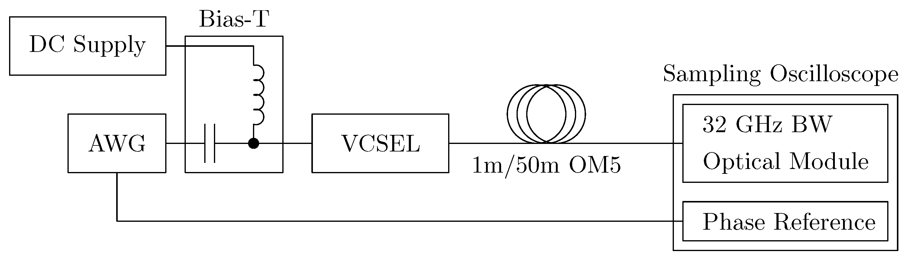
Figure 9 depicts the experimental measurement setup [
22]. A 22
bandwidth VCSEL wire-bonded to an RF connector and coupled into a lensed MMF fiber was used. It was connected to a Bias-T. The Bias-T combines an AC path, which is connected to an Arbitrary Waveform Generator (AWG) and a DC path, which is fed by a current source driving a bias current of 5
. The AWG is used to create a
long, 800
Pseudo-Random Binary Sequence (PRBS) which is pre-emphasized with a UI-spaced linear or adaptive FFEs with six Transmitter (TX) taps (two pre, one main, three post). The number of taps was chosen based on the length of the relaxation oscillations and the trade-off between better equalization (high amount of taps) and low computation complexity (low amount of taps). Since the filter effectively dampens the relaxation oscillations, increasing the amount of taps only gives diminishing returns after a certain number. The integrated 32
receiver of the sampling oscilloscope is used to receive the optical signal of the VCSEL. For transmission experiments, OM-5 fiber was connected in-line. Synchronization of the system is attained by generating a clock signal with the second channel of the AWG, driving the phase reference module and trigger input of the sampling oscilloscope.
BER performance was evaluated by exporting the Probability Density Function (PDF) eye diagram from the jitter and noise analysis software of the oscilloscope. Vertical bathtubs were calculated with the common method for Additive White Gaussian Noise (AWGN) channels of fitting normal distributions to the four PAM-4 levels and adding Q-functions [
23]. The bathtub curves for every one of the three eyes were then combined into one vertical bathtub curve. This method of calculating BER is undertaken because commercially available stand-alone linear receivers have limited bandwidth and are difficult to de-embed, thus limiting the performance in combination with a bit-error tester.
6. Measurement Results and Discussion
In this section, the measurement results are shown and discussed.
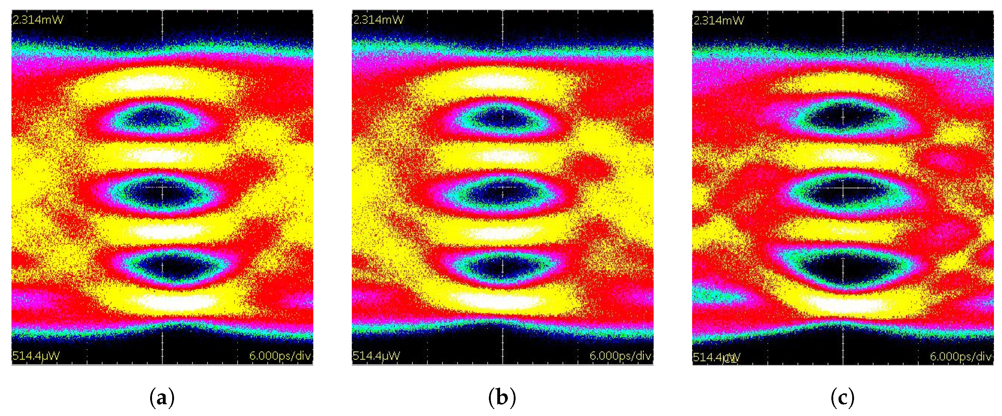
Figure 10 shows the resulting eye diagram for different forms of pre-emphasis.
In
Figure 10a, a linear FFE was used.
Figure 10b,c illustrate the results for the proposed digitally tuned non-linear FFE with a set of 4 as well as 12 coefficients. All measurements were performed at a baud rate of 40
. The average measured optical power was
for all three experiments. The adaptive structures are able to correct any skewing of the eyes. This was achieved by compensating the asymmetric rise-and-fall times through data-dependent pre-emphasis. To understand this effect, one can think of the VCSEL as an RC low-pass filter with a changing time constant. When a step function is applied, increasing the time constant of the filter can be counteracted by increasing the amplitude of the step, resulting in the same slew rate at the output. Although both adaptive structures are able to correct skewing, only the 12 sets of coefficient filter significantly increases the eye openings and achieves BER reduction. The BER reduces by a factor of 15, as shown in
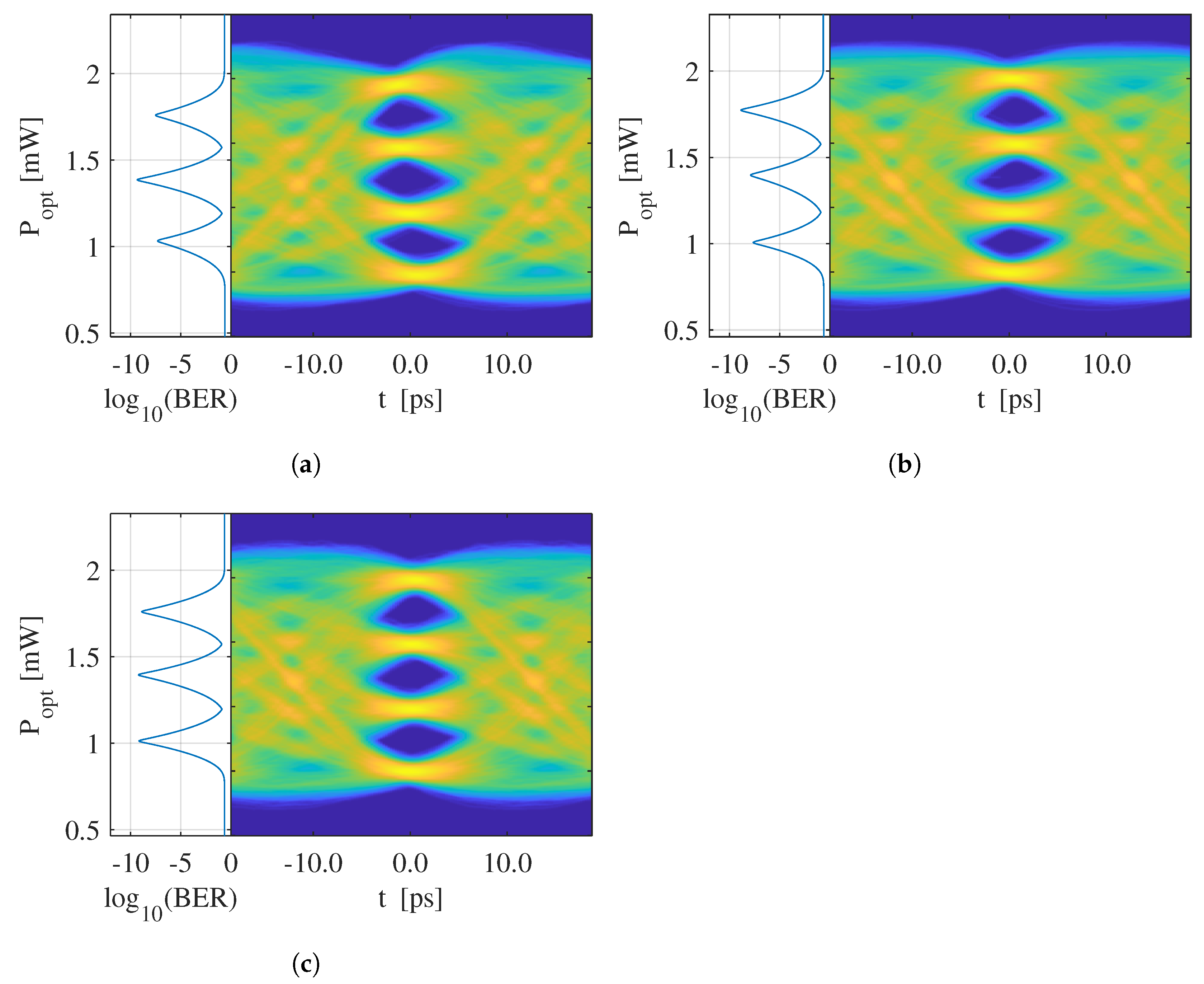
Table 2. When using four additional taps of Receiver (RX) equalization (added in the oscilloscope software), the effectiveness of the adaptive filter grows even bigger: The 12 coefficient filter achieves an over 30-fold decrease in BER in respect to the linear variant. Comparing the vertical bathtubs in
Figure 11a–c, it is obvious that the skewing is mainly limiting the eye performance of the linear filter because the BER is dominated by the top and bottom eye. Choosing a sub-par sampling point or large values of jitter would even amplify this effect since moving the sampling point to the right, the top eye’s BER would significantly increase, moving it to the left, the bottom eye would act accordingly. The four-coefficient filter (
Figure 11b) is mostly limited by mid-and bottom eye performance. This could simply be due to the fact that the slicing time where optimum BER performance is reached is a little off center, or that the topmost eye is most open. Interestingly, the Ratio of Level Mismatch (RLM) performance shown in
Table 2, varies a lot between the filters, even though DC levels were identical for all transmission experiments. The vertical bathtub using the 12 coefficient adaptive FFE shown in
Figure 11c, shows that all three eyes share roughly the same BER at the optimal sampling point, making it less susceptible to jitter.
Since the adaptive FFE with 12 sets of coefficients proved to be most effective, it was also tested at a baud rate of 56
. The measurement setup was changed by replacing the packaged and bonded VCSEL with a chip exhibiting a higher bandwidth of 28
. The optical device was mounted on a chuck, probed via a GS-probe and coupled into a fiber pigtail. Overall, the physical measurement setup was identical as in [
24]. A total of seven taps were used in the transmit adaptive FFE and the VCSEL was biased with a bias current of
.
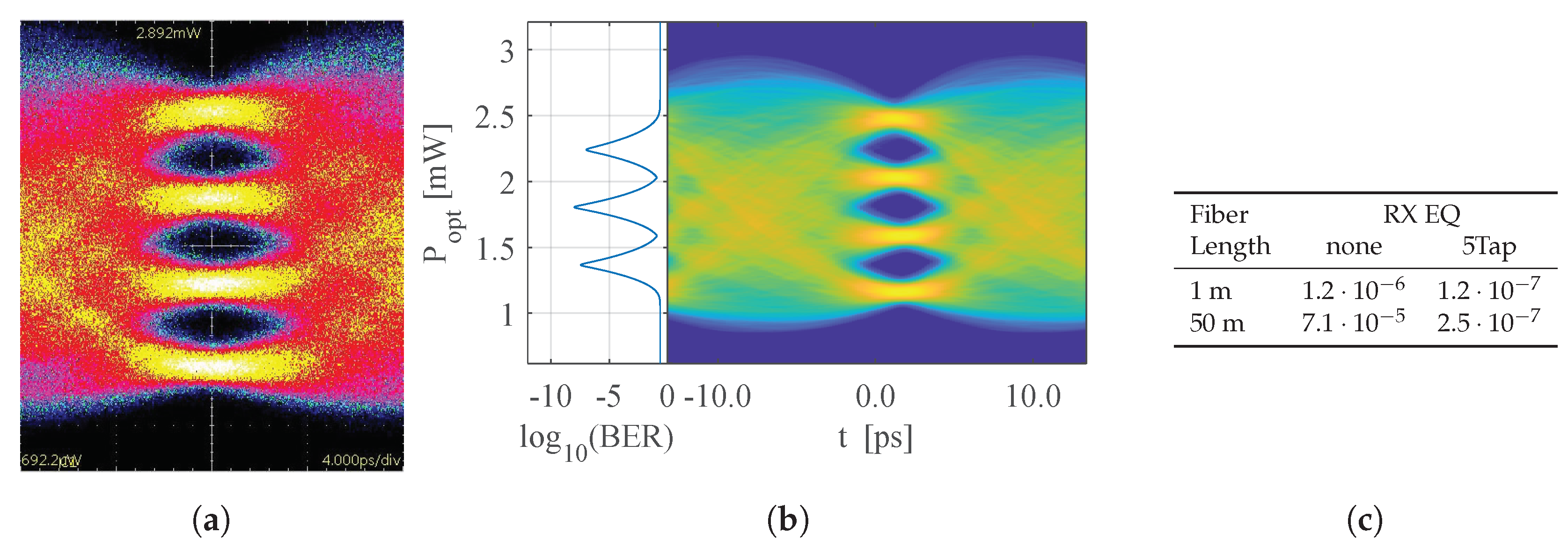
Figure 12a shows the output eye using the 12 coefficient adaptive FFE in the TX. It has an average optical output power of
. As before, the filter is again able to re-synchronize the eyes and remove skewing. When using 5 additional taps of linear equalization in the receiver (
Figure 12b), the BER can be improved from
to
. The transmission was also tested using 50
of OM5 fiber, simulating the use in server-rack environment.
Figure 12c reveals that the BER does not drop significantly for fiber lengths up to 50
when using receiver equalization. In comparison to SOTA NRZ VCSEL drivers [
6], a significant increase in data rate by a factor of
x is achieved. Although the BER is quite a bit higher than
, it is still below the Forward Error Correction (FEC) threshold of
for 3 overhead [
25]. Incorporating the FEC overhead, an increase in data rate by a factor of
x is reached.

 ,
, 


