The Acceleration Phenomenon of Shock Wave Induced by Nanosecond Laser Irradiating Silicon Assisted by Millisecond Laser

Abstract
:1. Introduction
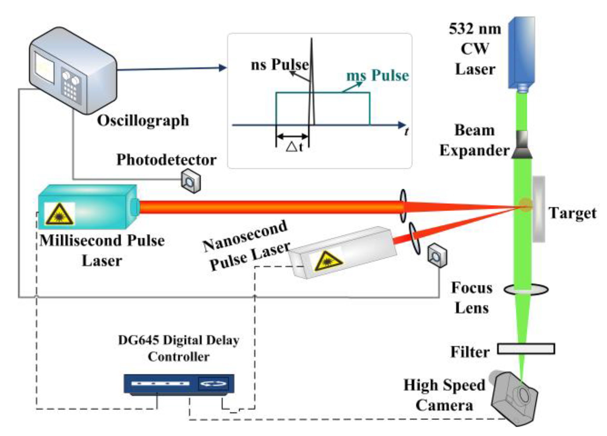
2. Experiment
3. Results
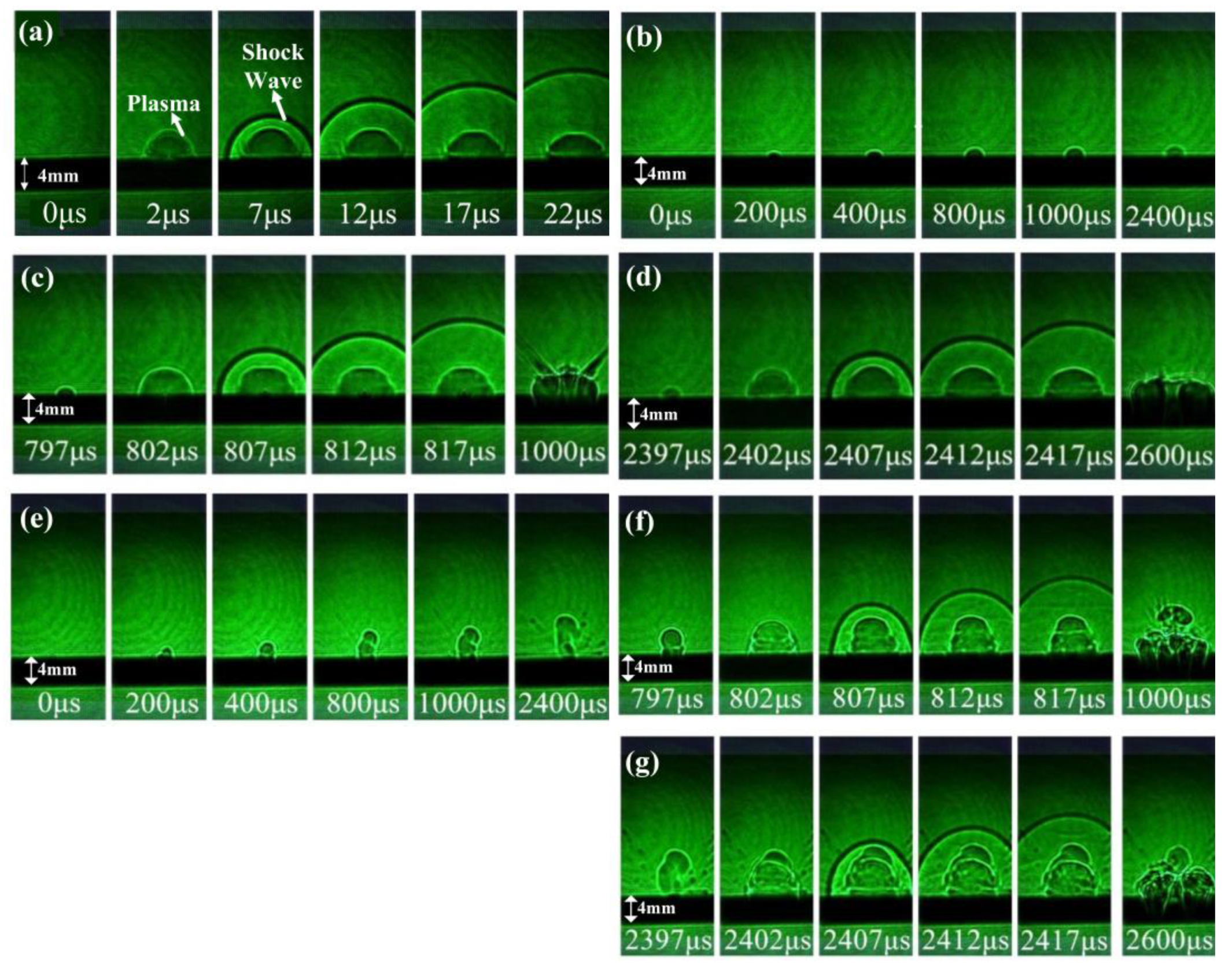
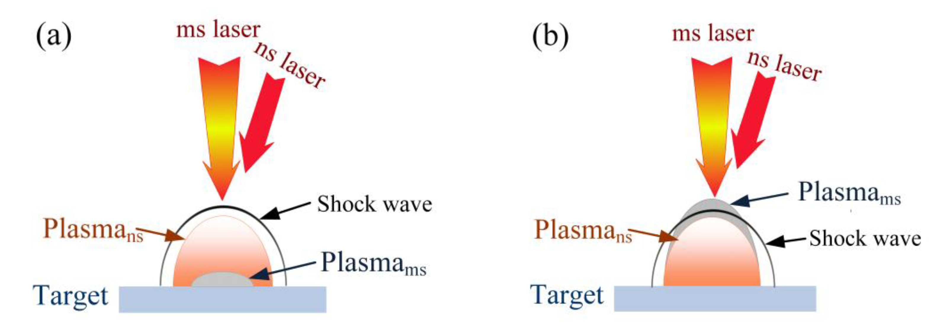
3.1. The Morphology Evolution of the ms-ns CPL-Induced Shock Wave
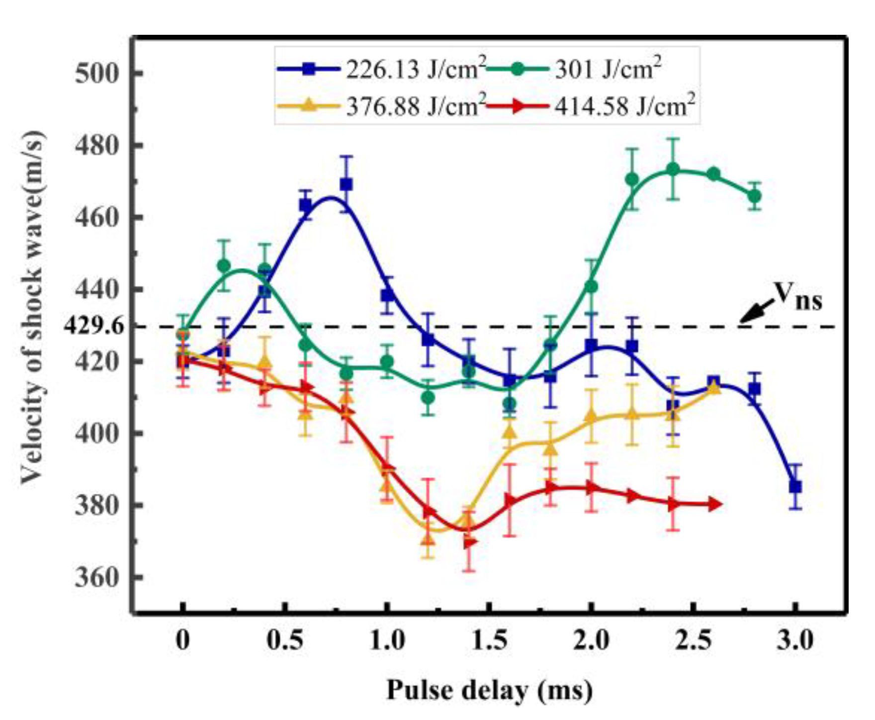
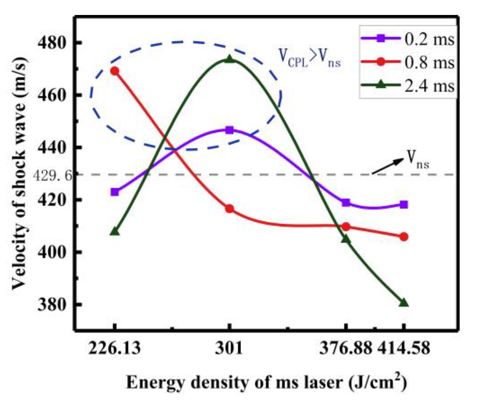
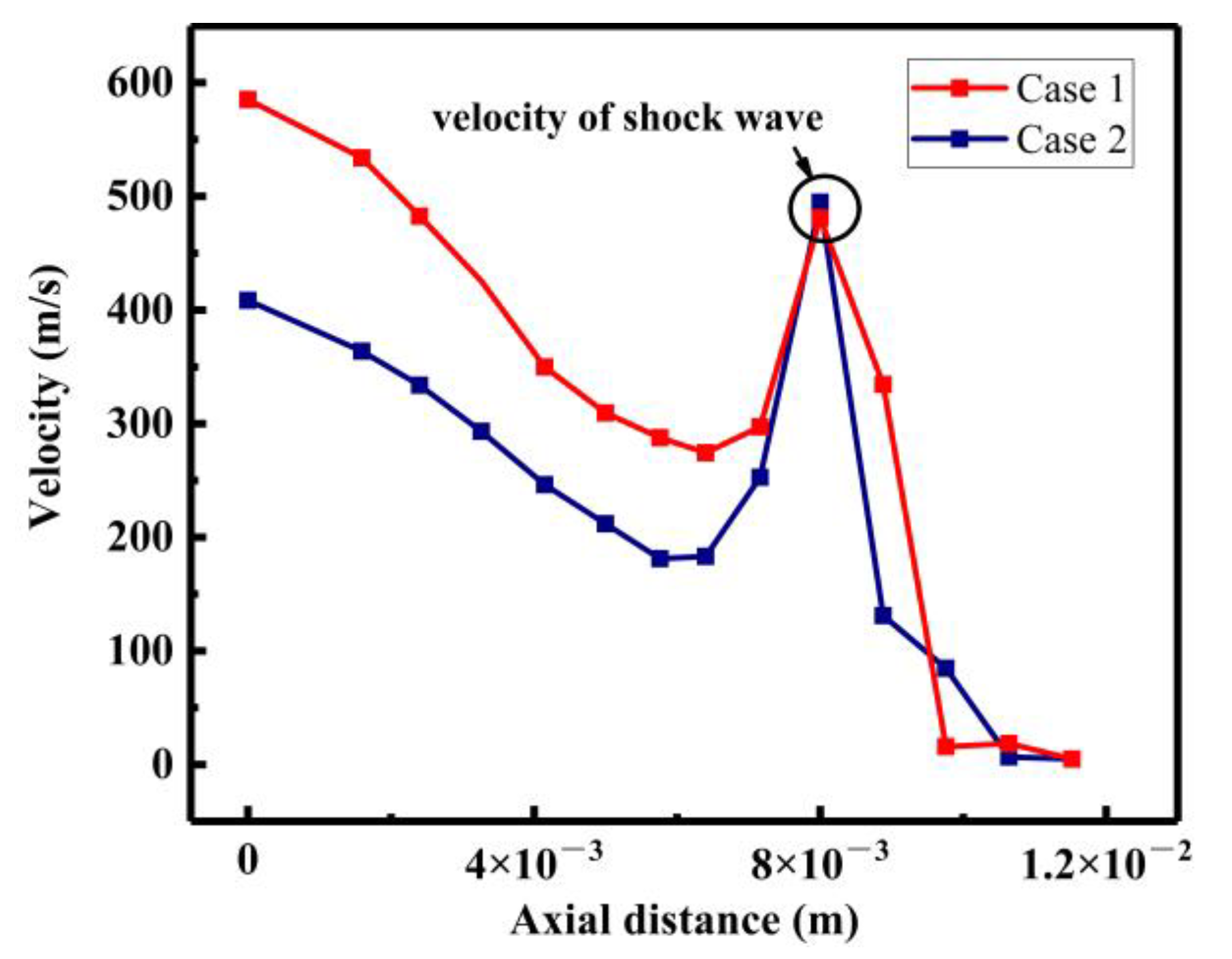
3.2. The Velocity of the ms-ns CPL-Induced Shock Wave
3.3. The Simulation Analysis of the ms-ns CPL-Induced Shock Wave
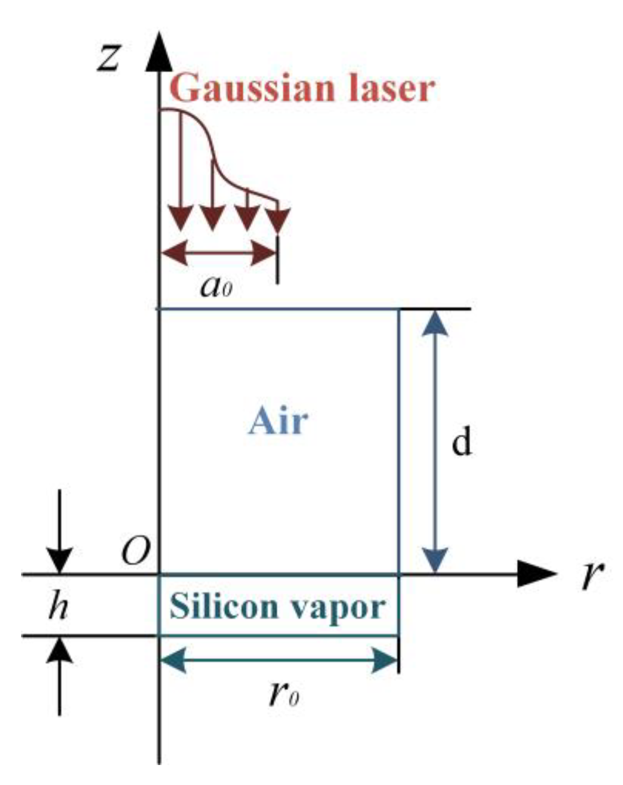
3.3.1. Calculation Model and Theory
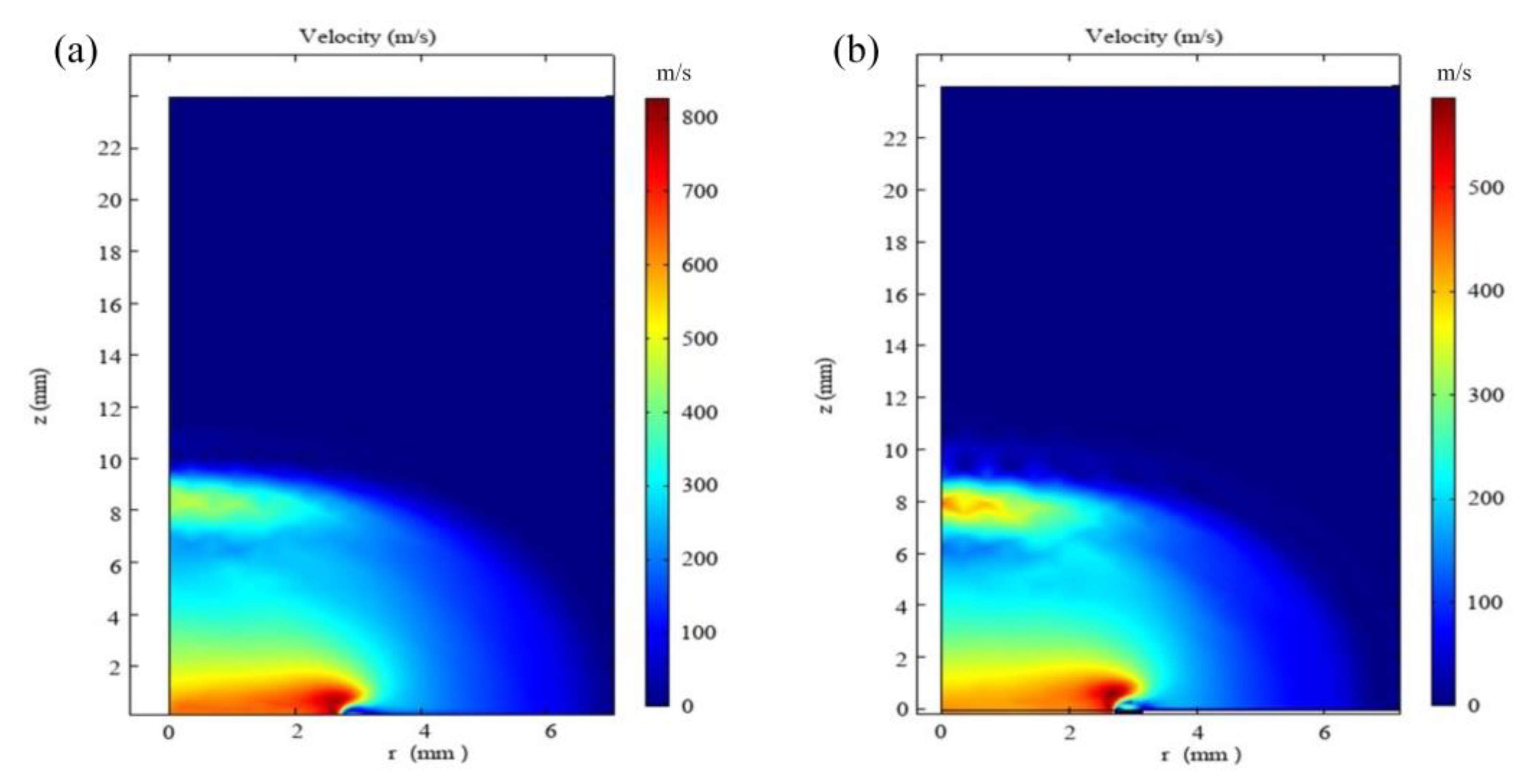
3.3.2. Calculation Results and Analysis
4. Discussion
5. Conclusions
Author Contributions
Funding
Institutional Review Board Statement
Informed Consent Statement
Data Availability Statement
Acknowledgments
Conflicts of Interest
References
- Esmiller, B.; Jacquelard, C.; Eckel, H.A.; Wdwin, E. Space debris removal by ground-based lasers: Main conclusions of the European project cleanspace. Appl. Opt. 2014, 53, 45–54. [Google Scholar] [CrossRef] [PubMed]
- Soulard, R.; Quinn, M.N.; Tajima, T.; Mourou, G. ICAN: A novel laser architecture for space debris removal. Acta Astronaut. 2014, 105, 192–200. [Google Scholar] [CrossRef]
- Tao, S.; Wu, B. Nanosecond laser pulse interactions with breakdown plasma in gas medium confined in a microhole. Appl. Phys. B Lasers Opt. 2013, 113, 251–258. [Google Scholar] [CrossRef]
- Yu, H.; Wu, X.; Yuan, Y.; Li, H.; Yang, J. Confined geometry and laser energy affect laser plasma propulsion. Opt. Express 2019, 27, 9763–9772. [Google Scholar] [CrossRef]
- Chen, J.; Tan, R.; Wu, J.; Lu, Y.; Zhu, Y. Air-breathing mode laser propulsion with a long-pulse TE CO2 laser. Chin. Opt. Lett. 2010, 8, 771–772. [Google Scholar] [CrossRef]
- Shukla, P.; Crookes, R.; Wu, H. Shock-wave induced compressive stress on alumina ceramics by laser peening. Mater. Design 2019, 167, 107626. [Google Scholar] [CrossRef]
- Yu, H.; Wu, X.; Li, G.; Yuan, Y.; Yang, J. Particle removal is explored by the motion of individual particles based on laser-induced plasma shock wave. Opt. Commun. 2020, 460, 125205. [Google Scholar] [CrossRef]
- Zhaia, Z.; Wang, W.; Meia, X.; Wanga, K.; Yanga, H. Influence of plasma shock wave on the morphology of laser drilling in different environments. Opt. Commun. 2017, 390, 49–56. [Google Scholar] [CrossRef]
- Unaldi, S.; Papadopoulos, K.; Rondepierre, A.; Rouchausse, Y.; Karanika, A.; Deliane, F.; Tserpes, K.; Floros, G.; Richaud, E.; Berthe, L. Towards selective laser paint stripping using shock waves produced by laser-plasma interaction for aeronautical applications on AA 2024 based substrates. Opt. Laser Technol. 2021, 414, 107095. [Google Scholar]
- Lu, J.Z.; Xue, K.N.; Lu, H.F.; Xing, F.; Luo, K.Y. Laser shock wave-induced wear property improvement and formation mechanism of laser cladding Ni25 coating on H13 tool steel. J. Mater. Process. Technol. 2021, 296, 117207. [Google Scholar] [CrossRef]
- Krasyuk, I.K.; Pashinin, P.P.; Semenov, A.Y.; Khishchenko, K.V.; Fortov, V.E. Study of extreme states of matter at high energy densities and high strain rates with powerful lasers. Laser Phys. 2016, 26, 094001. [Google Scholar] [CrossRef]
- Abrosimov, S.A.; Bazhulin, A.P.; Voronov, V.V.; Geras’kin, A.A.; Krasyuk, I.K.; Pashinin, P.P.; Semenov, A.Y.; Stuchebryukhov, I.A.; Khishchenko, K.V.; Fortov, V.E. Specific features of the behaviour of targets under negative pressures created by a picosecond laser pulse. Quantum Electron. 2013, 43, 246–251. [Google Scholar] [CrossRef]
- Cao, S.Q.; Su, M.; Jiao, Z.H.; Qi, M. Dynamics and density distribution of laser-produced plasma using optical interferometry. Phys. Plasmas 2018, 25, 063302. [Google Scholar] [CrossRef]
- Wang, Y.; Liu, C.; Li, C. Evolution of ns pulsed laser induced shock wave on aluminum surface by numerical simulation. Results Phys. 2021, 22, 103920. [Google Scholar] [CrossRef]
- Nechay, A.N.; Perekalov, A.A.; Chkhalo, N.I.; Salashchenko, N.N.; Korepanov, M.A.; Koroleva, M.R. Emission properties of targets based on shock waves excited by pulsed laser radiation. Opt. Laser Technol. 2021, 142, 107250. [Google Scholar] [CrossRef]
- Yoh, J.J.; Lee, H.; Choi, J.; Lee, K.; Kim, K. Ablation-induced explosion of metal using a high-power Nd:YAG laser. J. Appl. Phys. 2008, 103, 043511. [Google Scholar] [CrossRef]
- Gregorčič, P.; Možina, J. High-speed two-frame shadowgraphy for velocity measurements of laser-induced plasma and shock-wave evolution. Opt. Lett. 2011, 36, 2782. [Google Scholar] [CrossRef]
- Cao, S.; Su, M.; Min, Q.; Sun, D.; Ma, P.; Wang, K.; Jiao, Z.; Dong, C. Dynamics and density distribution of laser-produced Al plasmas using optical interferometry and optical emission spectroscopy. J. Quant. Spectrosc. Radiat. Transf. 2019, 225, 69–75. [Google Scholar] [CrossRef]
- Kraft, S.; Schille, J.; Mauersberger, S.; Schneider, L.; Loeschner, U. Pump-probe imaging for process control and optimization in high-speed laser micro machining. In Proceedings of the Laser-based Micro- and Nanoprocessing XIV, San Francisco, CA, USA, 12 March 2020. [Google Scholar]
- Cao, S.; Su, M.; Ma, P.; Wang, K.; Dong, C. Expansion dynamics and emission characteristics of nanosecond–picosecond collinear double pulse laser-induced Al plasma in air. J. Quant. Spectrosc. Radiat. Transf. 2019, 242, 106773. [Google Scholar] [CrossRef]
- Cao, S.; Su, M.; Liu, J.; Min, Q.; Dong, C. Expansion dynamics and compression layer in collinear double-pulse laser produced plasmas in a vacuum. Phys. Plasmas 2020, 27, 052101. [Google Scholar] [CrossRef]
- Yang, Z.; Wei, W.; Han, J.; Jian, W.; Jia, S. Experimental study of the behavior of two laser produced plasmas in air. Phys. Plasmas 2015, 22, 073511. [Google Scholar] [CrossRef]
- Li, J.; Zhang, W.; Zhou, Y.; Yuan, B.; Cai, J.; Jin, G. The acceleration mechanism of shock wave induced by millisecond-nanosecond combined-pulse laser on silicon. Plasma Sci. Technol. 2021, 23, 055507. [Google Scholar] [CrossRef]
- Rao, K.H.; Smijesh, N.; Chetty, D.; Litvinyuk, I.V.; Sang, R.T. Effect of double pulse laser irradiation on the dynamics of picosecond laser-produced plasma. Phys. Plasmas 2020, 27, 083518. [Google Scholar]
- Smijesh, N.; Rao, K.H.; Chetty, D.; Litvinyuk, I.V.; Sang, R.T. Plasma plumes produced by laser ablation of Al with single and double pulse schemes. Opt. Lett. 2017, 43, 6081–6084. [Google Scholar] [CrossRef] [PubMed]
- Wang, Q.; Qi, H.; Zeng, X.; Chen, A.; Gao, X.; Jin, M. Time-resolved spectroscopy of collinear femtosecond and nanosecond dual-pulse laser-induced Cu plasmas. Plasma Sci. Technol. 2021, 23, 121–127. [Google Scholar] [CrossRef]
- Jia, X.; Chen, Y.; Zhu, G.; Wang, H.; Zhu, X. Experimental study on the optimum matching of CW-nanosecond combined pulse laser drilling. Appl. Opt. 2019, 58, 9105. [Google Scholar] [CrossRef]
- Pan, Y.; Lv, X.; Zhang, H.; Chen, J.; Han, B.; Shen, Z.; Lu, J.; Ni, X. Millisecond laser machining of transparent materials assisted by a nanosecond laser with different delays. Opt. Lett. 2016, 41, 2807–2810. [Google Scholar] [CrossRef]
- Hosoya, N.; Katsumata, T.; Kajiwara, I.; Onuma, T.; Kanda, A. Measurements of S0 mode Lamb waves using a high-speed polarization camera to detect damage in transparent materials during non-contact excitation based on a laser-induced plasma shock wave. Opt. Laser Eng. 2022, 148, 106770. [Google Scholar] [CrossRef]
- Sun, X.; Yu, Q.; Bai, X.; Jin, G.; Cai, J.; Yuan, B. Substrate Cleaning Threshold for Various Coated Al Alloys Using a Continuous-Wave Laser. Photonics 2021, 8, 359. [Google Scholar] [CrossRef]
- Yuan, B.; Zhang, Y.; Zhang, W.; Dong, Y.; Jin, G. The Effect of Spot Size Combination Mode on Ablation Morphology of Aluminum Alloy by Millisecond-Nanosecond Combined-Pulse Laser. Materials 2018, 11, 1419. [Google Scholar] [CrossRef]
- Wang, L.; Cai, J. Study on the effect of focal position change on the expansion velocity and propagation mechanism of plasma generated by millisecond pulsed laser-induced fused silica. Plasma Sci. Technol. 2023, 25, 035507. [Google Scholar] [CrossRef]
- Zhang, W.; Wei, Z.; Wang, Y.B.; Jin, G.Y. Numerical simulation of laser-supported combustion wave induced by millisecond-pulsed laser on aluminum alloy. Laser Phys. 2016, 26, 015001. [Google Scholar] [CrossRef]
- Mcbride, B.J.; Gordon, S.; Reno, M.A. Coefficients for Calculating Thermodynamic and transport Properties of Individual Species, 1st ed.; NASA TM-4513: Washington, DC, USA, 1993; pp. 9–47. [Google Scholar]
- Andreopoulos, J.; Muck, K.C.; Dussauge, J.P.; Smits, A.J. Turbulence structure in a shock wave/turbulent boundary-layer interaction. AIAA J. 2012, 27, 862–869. [Google Scholar]
- Liou, W.W.; Huang, G.; Shih, T.H. Turbulence model assessment for shock wave/turbulent boundary-layer interaction in transonic and supersonic flows. Comput. Fluids 2000, 29, 275–299. [Google Scholar] [CrossRef]
- Maher, W.E.; Hall, R.B.; Johnson, R.R. Experimental study of igition and propagation of laser-supported detonation waves. J. Appl. Phys. 1974, 45, 2138–2145. [Google Scholar] [CrossRef]


| The Pulse Delay of Max VCPL | The Acceleration Multiple of VCPL | |||
|---|---|---|---|---|
| Case 1 | 226.13 | 12 | 0.8 ms | 1.1 |
| Case 2 | 301 | 12 | 2.4 ms | 1.1 |
| Parameters | Expression |
|---|---|
| the density of silicon vapor /kg∙m−3 | 2540 − 2.19 × 10⁻²∙ T − 1.21 × 10⁻⁵∙T2 |
| the viscosity coefficient of silicon vapor η/Pa | 5.52 × 10⁻⁶ + 9.8 × 10⁻⁹∙T + 4.97 × 10⁻¹²∙T2 − 1.07 × 10⁻¹⁵∙T3 + 7.77 × 10⁻²⁰∙T4 |
| the specific heat capacity of silicon vapor Cp/J∙(kg∙K)−1 | 798.42 − 0.12∙T + 6.85 × 10⁻⁵∙T2 − 2.52 × 10⁻⁹∙T3 − 2.65 × 10⁻¹²∙T4 |
| the thermal conductivity of silicon vapor λ/W∙(m∙K)−1 | 6.12 × 10⁻³ + 1.09 × 10⁻⁵∙T + 5.52 × 10⁻⁹∙T2 − 1.19 × 10⁻¹²∙T3 + 8.63 × 10⁻¹⁷∙T4 |
Disclaimer/Publisher’s Note: The statements, opinions and data contained in all publications are solely those of the individual author(s) and contributor(s) and not of MDPI and/or the editor(s). MDPI and/or the editor(s) disclaim responsibility for any injury to people or property resulting from any ideas, methods, instructions or products referred to in the content. |
© 2023 by the authors. Licensee MDPI, Basel, Switzerland. This article is an open access article distributed under the terms and conditions of the Creative Commons Attribution (CC BY) license (https://creativecommons.org/licenses/by/4.0/).
Share and Cite
Li, J.; Zhang, W.; Li, Y.; Jin, G. The Acceleration Phenomenon of Shock Wave Induced by Nanosecond Laser Irradiating Silicon Assisted by Millisecond Laser. Photonics 2023, 10, 260. https://doi.org/10.3390/photonics10030260
Li J, Zhang W, Li Y, Jin G. The Acceleration Phenomenon of Shock Wave Induced by Nanosecond Laser Irradiating Silicon Assisted by Millisecond Laser. Photonics. 2023; 10(3):260. https://doi.org/10.3390/photonics10030260
Chicago/Turabian StyleLi, Jingyi, Wei Zhang, Ye Li, and Guangyong Jin. 2023. "The Acceleration Phenomenon of Shock Wave Induced by Nanosecond Laser Irradiating Silicon Assisted by Millisecond Laser" Photonics 10, no. 3: 260. https://doi.org/10.3390/photonics10030260