Communication

Optimum Design of Glass–Air Disordered Optical Fiber with Two Different Element Sizes

1
School of Computer and Communication Engineering, Changsha University of Science and Technology, Changsha 410114, China
2
Key Laboratory of Optoelectronics and Telecommunication of Jiangxi Province, Department of Photoelectric, Information Science and Engineering, Jiangxi Normal University, Nanchang 330022, China
*
Author to whom correspondence should be addressed.
Photonics 2023, 10(3), 259; https://doi.org/10.3390/photonics10030259
Submission received: 6 January 2023 / Revised: 25 February 2023 / Accepted: 27 February 2023 / Published: 28 February 2023
(This article belongs to the Special Issue Fiber Optics and Its Applications)

Abstract

:
This paper presents a detailed study investigating the effect of the material refractive index distribution at the local position of a glass–air disordered optical fiber (G-DOF) on its localized beam radius. It was found that the larger the proportion of the glass material, the smaller its localized beam radius, which means that the transverse Anderson localization (TAL) effect would be stronger. Accordingly, we propose a novel G-DOF with large-size glass elements doped in the fiber cross-section. The simulation results show that the doped large-size glass elements can reduce the localized beam radius in the doped region and has a very tiny effect on the undoped region, thus contributing to reducing the average localized beam radius of G-DOF.

1. Introduction

Disordered optical fiber (DOF) [1,2] is a new type of optical fiber whose material refractive index is disordered in its cross-section but constant in the longitudinal direction. DOF utilizes the transverse Anderson localization (TAL) effect [3,4] to confine and transmit beams, so it is also known as a transverse Anderson localization optical fiber. Optical beams at any incident position on the DOF cross-section could transfer along the fiber [5], and the spatial isolation between different localized beams is considerably high [6]. So far, DOF has shown a great application potential in beam multiplexing [5], random lasing [7], wave-front shaping [8], supercontinuum generation [9], high resolution image transmission [10,11,12,13], and so on.
The first DOF, reported in 2012, was produced by the University of Wisconsin and Corning together. DOFs have experienced ten years of development, and four different types of DOFs have been fabricated, namely polymer DOF [14,15], G-DOF [16], chalcogenide DOF [17], and tellurite DOF [18], to transmit light with a different wavelength. To enhance the TAL effect of DOFs, researchers have explored in detail the influence of the refractive index difference between two different materials elements: the proportion and the size of the two different material elements on the localized beam radius. It is agreed that a larger material refractive index difference between the two elements and smaller element size led to a smaller average localized beam radius [15]. Especially when the proportion of each kind of element is around 50% [15,19,20], the corresponding localized beam radius would reach the minimum value. The above research has focused on optimizing the design of DOFs from the perspective of the overall structure. However, the influence of the local structure of the DOF cross-section has been rarely reported. During the simulation, we noticed that the localized beam radius varies with different incident positions on the DOF cross-section. This implies that the local material refractive index distribution can regulate the localized beam radius.
In this paper, we focus on G-DOF and study in detail the influence of the material refractive index distribution at the light incidence position on the localized beam radius. We discovered that the localized beam radius would decrease while increasing the proportion of the glass material. On this basis, we propose a method to enhance the TAL effect by doping glass elements with the same size as the light source into G-DOF. The simulation results show that this method reduces the localized beam radius of the doped region by about 50%, with an ignorable side effect on the undoped region.

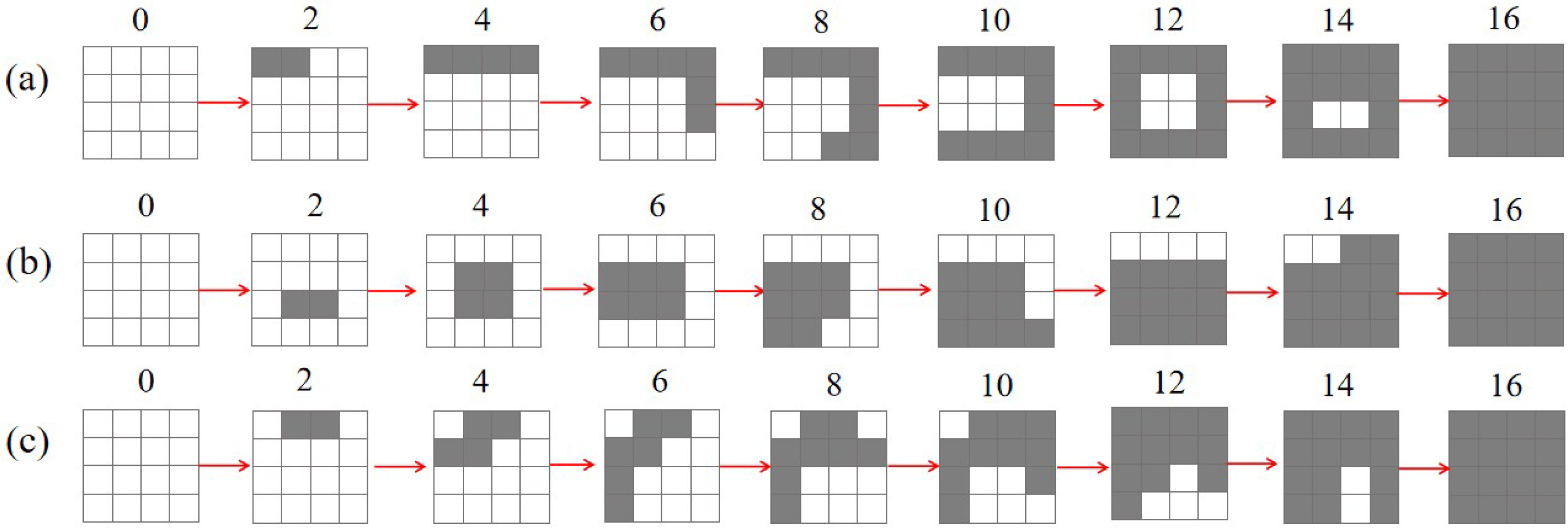
2. Schematic Topology and Design Principle

Figure 1 shows a schematic cross-sectional structure of the G-DOF used in our study. The fiber cross-section contains 250 × 250 small square elements with a side length of a = 0.6 μm. The grey squares represent the material glass (SiO2), and the white squares represent air. Each type of elements consists of 50% of the total and is randomly mixed. The modelling process used for the G-DOF is similar to that described in reference [20]. We choose square elements rather than round elements because round elements cannot be arranged closely without any gap. Moreover, DOF models with square elements have been widely used in simulations and calculations in previous theoretical studies [15,18].
Then, a Gaussian beam with diameter of 2.4 μm (which equals 4a) and a wavelength of 0.633 μm was chosen as the light source. The beam is incident at the red marked section, of which the zooming up view is shown in the inset of Figure 1. It is easy to see that the beam incident region covers 16 elements numbered from 1 to 16. Next, by utilizing the Rsoft software and the finite-difference beam propagation method (FD-BPM), we simulated and calculated the influence of the material refractive index distribution of those 16 elements on the localized beam radius. Additionally, the method for calculating the localized beam radius is referenced in [15,19]. In this paper, the fiber transmission distance was set to 2 cm because the diffusion of the optical field will become stable within this distance.

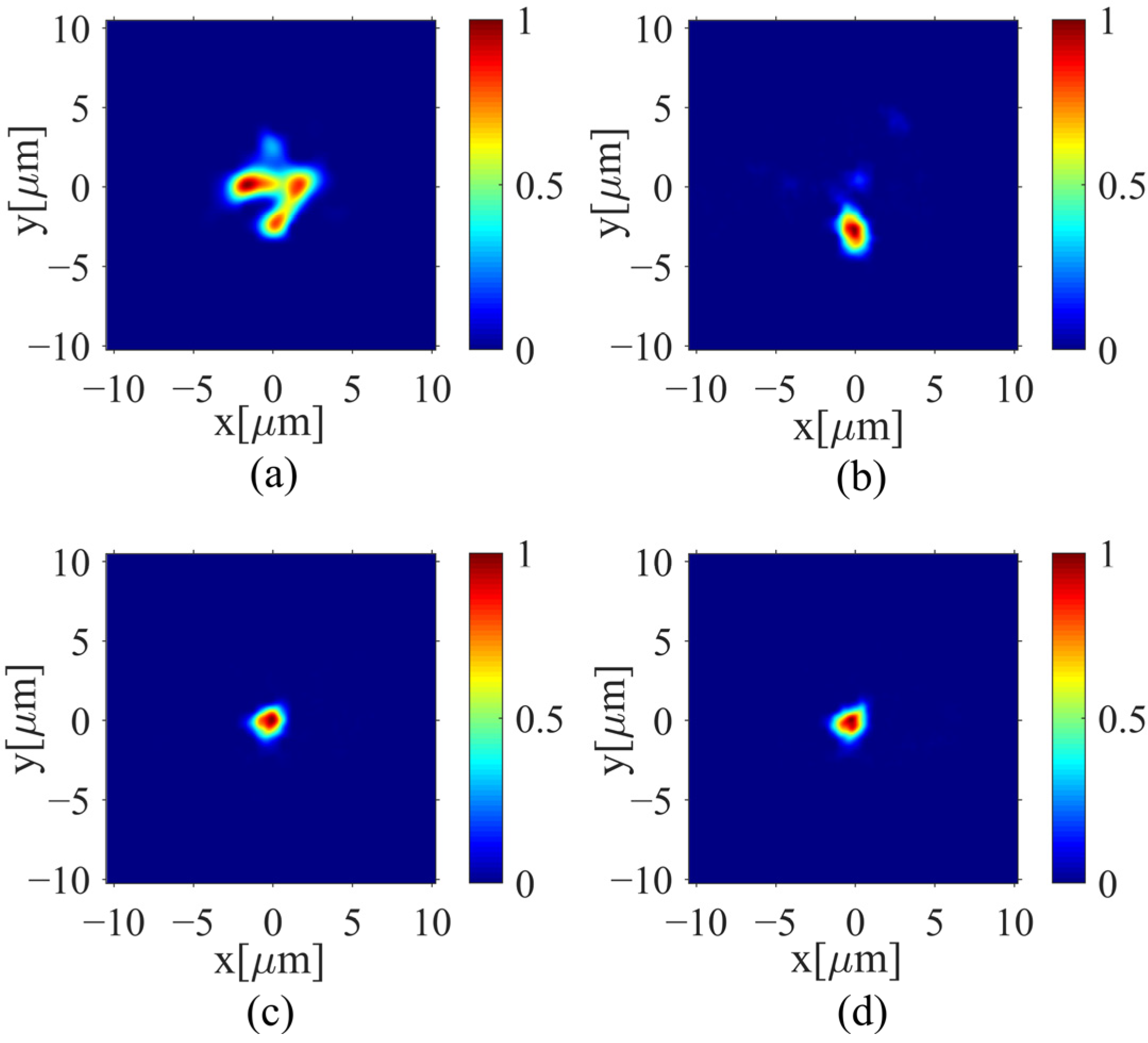
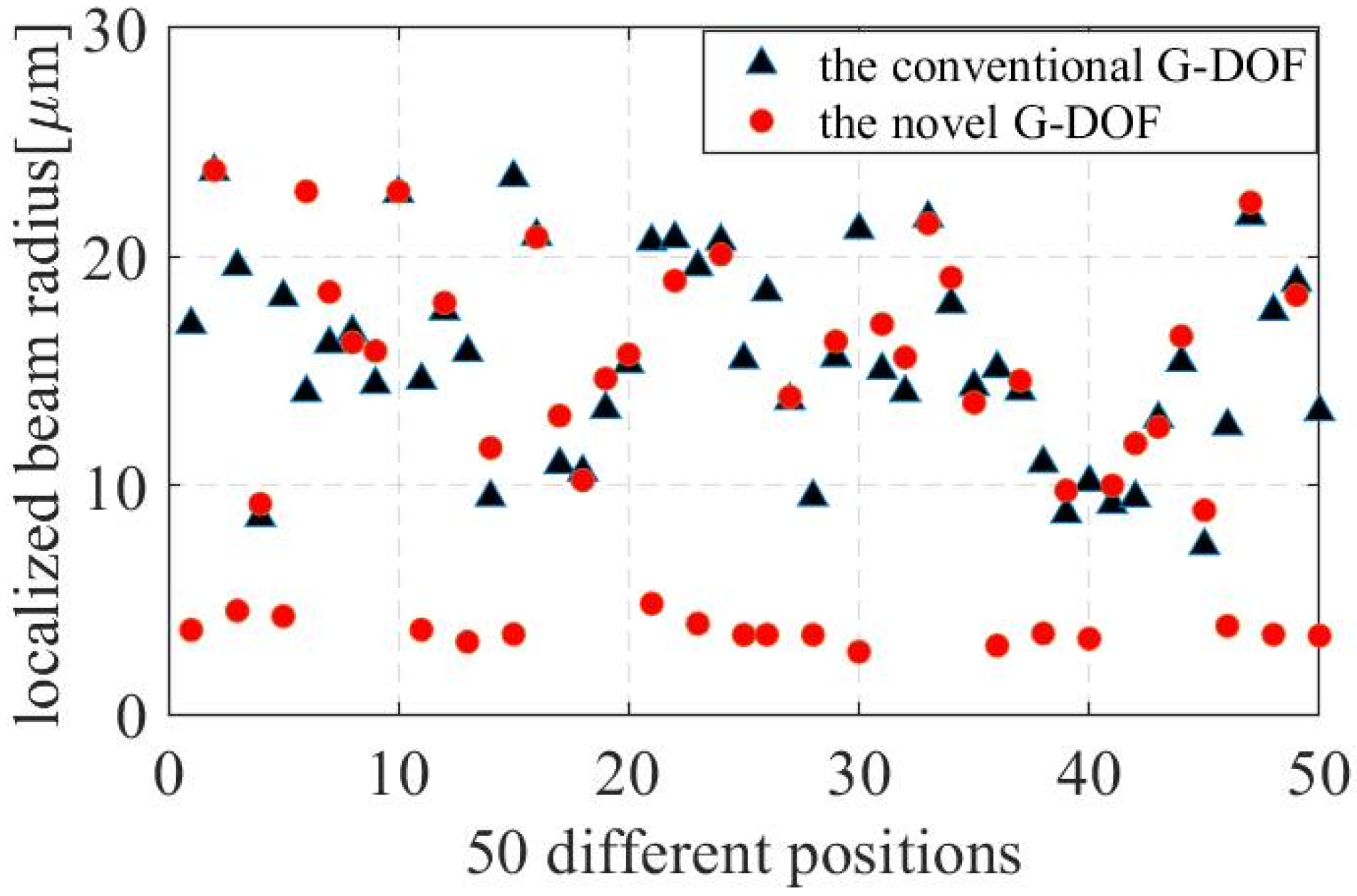
3. Simulation and Data Analysis

Figure 2 describes the influence of the number of glass elements on the localized beam radius when three different methods are used to increase the number of glass elements in the light incident region. The first method is to add the glass elements from the outer layer to the inner layer with the sequence of 1, 2, 3, 4, 5, 6, 7, 8, 9, 10, 11, 12, 13, 14, 15, 16. The second method is to add the glass elements from the inner layer to the outer layer with the sequence of 16, 15, 14, 13, 12, 11, 10, 9, 8, 7, 6, 5, 4, 3, 2, 1. The third method is to add the glass element randomly with the sequence of 2, 3, 13, 12, 11, 10, 14, 5, 4, 6, 16, 1, 9, 7, 15, 8. To help readers better understand, we have drawn the process of these three methods for increasing the number of glass elements, as shown in Figure 3. Furthermore, it can be seen from Figure 2 that the localized beam radius will become smaller as the number of glass elements increases, regardless of the order in which they are added. Specifically, compared with the other two methods, the second method is conducive to achieving the smallest localized beam radius. This means that the central elements play a more vital role in beam confinement. The inset in Figure 2 displays the optical field distribution for the second method when the number of glass elements equals to 0, 8, and 16, respectively. It is obvious that the optical field energy tends to converge as the proportion of the glass material increases. The above results indicate that the local TAL effect of G-DOF can be enhanced by increasing the proportion of the glass elements in the light incident area. In fact, this phenomenon may also be explained as follows: when the proportion of the glass material in the light incident region increases, its effective refractive index increases and creates total internal reflection conditions with the surrounding area, thus leading to a better beam confinement.
Hereby, we proposed a new type of G-DOF in which 4a-width glass elements are doped into the cross-section of the conventional G-DOF, and we call it the novel G-DOF. Figure 4 shows the cross-section schematic of the novel G-DOF. Obviously, the difference between the novel G-DOF and the conventional G-DOF is that the cross-section of the novel G-DOF also contains some large-size glass elements. In Figure 4, the variable X represents the central distance between adjacent 4a-width glass elements, whose value should be greater than 4a. Now, the question is what is the most appropriate value of X? To answer this question, we sent a Gaussian beam with diameter of 4a-width (2.4 μm) to the novel G-DOF center, and studied in detail the effect of the X value on the optical field distribution when X increases from 4a to 10a, as shown in Figure 5a–d. It is easy to find that when X equals 4a, the optical field energy at the incident position is greatly coupled to the surrounding area. When X equals 6a, the center of the optical field is seriously shifted. Until the value of X increases to 8a, the optical field energy is well confined near the light incident position. Although continuing to increase, X is beneficial to obtain a more stable optical field distribution, thus we chose to set X to 8a in the optimization design of the novel G-DOF, which can not only introduce more 4a-wide glass elements, but also effectively prevent energy coupling between each other.
Then, the difference in the average localized beam radius between the optimized novel G-DOF and the conventional G-DOF was compared. The localized beam radius at 50 different positions on the cross-section of both novel G-DOF and conventional G-DOF are calculated, as shown in Figure 6. In conventional G-DOF, the localized beam radius is mostly concentrated within the range of 8 μm to 24 μm, with an average value of 15.6 μm. However, in the novel G-DOF, we have observed that the localized beam radius at certain locations is less than 5 μm, which corresponds to regions doped with 4a-width glass elements. In contrast, at other locations between 2 4a-width glass elements, the beam radius falls within the range of 8–24 μm, which is similar to the beam radius of the conventional G-DOF. The average localized beam radius for those 50 sampled points is 11.6 μm. The results show that the proposed novel G-DOF structure can reduce the localized beam radius of the doped region by more than 50%, with little effect on the undoped region. This ultimately leads to reducing the overall average localized beam radius by 25.6%.
To help readers better understand why doping these 4a-width glass elements can help reduce the average localized beam radius of G-DOF, Figure 7 shows the effect of the doped 4a-width glass elements on the optical field distribution of the doped and undoped regions, respectively. In Figure 7a, five incident light sources are arranged at five adjacent doped 4a-width glass elements. Obviously, the beam is well confined to a very small area, corresponding to an average localized beam radius of less than 5 μm. In Figure 7b, the five incident light sources are set at the centers of five adjacent undoped region. We can see that the beam is distributed over a larger area. Additionally, its average localized beam radius is comparable to that of conventional G-DOF. In a word, the doping of 4a-width glass elements reduces the localized beam radius in the doped region while having little effect on the undoped region, thus helping to reduce the overall average localized radius of G-DOF.

4. Conclusions

In summary, we discussed in detail how the distribution of the material refractive index at the light incident position affects its TAL effect. Here, three different methods were used to increase the number of glass elements at the light incident position. We found that the TAL effect would be stronger as the proportion of the glass elements increases, especially when the glass elements are close to the beam center. On the basis of the above research, we proposed a new method to enhance the TAL effect of G-DOF by adding glass elements with the same size as the light source in its cross-section. The simulation results show that this method could reduce the localized beam radius of the doped region by more than 50%, with a negligible effect on the undoped region. Ultimately, this method successfully reduced the overall average localized beam radius value by 25.6%. This study provides a new idea for optimizing the design of G-DOF.

Author Contributions

Conceptualization and methodology J.Z. and C.H.; software, validation, and writing—original draft preparation, J.Z. and C.H.; data analysis, J.Z. and C.H; investigation, Y.Z., Y.M. and W.C.; writing—review and editing, J.Z. and H.L.; funding acquisition, J.Z. and H.L. All authors have read and agreed to the published version of the manuscript.

Funding

This work is supported by the Scientific Research Fund of Hunan Provincial Education Department of China (Grant No. 22B0324), the Natural Science Foundation of Hunan Province of China (Grant No. 2020JJ5606), and National Natural Science Foundation of China (Grants 11804133).

Institutional Review Board Statement

Not applicable.

Informed Consent Statement

Not applicable.

Data Availability Statement

Data is contained within the article.

Conflicts of Interest

The authors declare no conflict of interest.

References

  1. Mafi, A.; Ballato, J. Review of a Decade of research on disordered Anderson localizing optical fibers. Front. Phys. 2021, 9, 681. [Google Scholar] [CrossRef]
  2. Mafi, A.; Ballato, J.; Koch, K.W.; Schülzgen, A. Disordered Anderson localization optical fibers for image transport—A review. J. Light. Technol. 2019, 37, 5652–5659. [Google Scholar] [CrossRef] [Green Version]
  3. De Raedt, H.; Lagendijk, A.D.; de Vries, P. Transverse localization of light. Phys. Rev. Lett. 1989, 62, 47. [Google Scholar] [CrossRef] [PubMed] [Green Version]
  4. Schwartz, T.; Bartal, G.; Fishman, S.; Segev, M. Transport and Anderson localization in disordered two-dimensional photonic lattices. Nature 2007, 446, 52–55. [Google Scholar] [CrossRef] [PubMed]
  5. Karbasi, S.; Koch, K.W.; Mafi, A. Multiple-beam propagation in an Anderson localized optical fiber. Opt. Express 2013, 21, 305–313. [Google Scholar] [CrossRef] [PubMed] [Green Version]
  6. Ruocco, G.; Abaie, B.; Schirmacher, W.; Mafi, A.; Leonetti, M. Disorder-induced single-mode transmission. Nat. Commun. 2017, 8, 14571. [Google Scholar] [CrossRef] [PubMed] [Green Version]
  7. Abaie, B.; Mobini, E.; Karbasi, S.; Hawkins, T.; Ballato, J.; Mafi, A. Random lasing in an Anderson localizing optical fiber. Light Sci. Appl. 2017, 6, e17041. [Google Scholar] [CrossRef] [PubMed] [Green Version]
  8. Abaie, B.; Peysokhan, M.; Zhao, J.; Antonio-Lopez, J.E.; Amezcua-Correa, R.; Schülzgen, A.; Mafi, A. Disorder-induced High-Quality Wavefront in an Anderson localizing optical fiber. Optica 2018, 5, 984–987. [Google Scholar] [CrossRef] [Green Version]
  9. Gausmann, S.; Hu, X.; Zhao, J.; Habib, M.; Cheng, H.; Antonio-Lopez, J.E.; Yu, X.; Amezcua-Correa, R.; Schülzgen, A. Tunable dispersion and supercontinuum generation in disordered glass-air Anderson localization fiber. J. Light. Technol. 2022, 1–10. [Google Scholar] [CrossRef]
  10. Karbasi, S.; Frazier, R.J.; Koch, K.W.; Hawkins, T.; Ballato, J.; Mafi, A. Image transport through a disordered optical fibre mediated by transverse Anderson localization. Nat. Commun. 2014, 5, 3362. [Google Scholar] [CrossRef] [PubMed] [Green Version]
  11. Karbasi, S.; Koch, K.W.; Mafi, A. Image transport quality can be improved in disordered waveguides. Opt. Commun. 2013, 311, 72–76. [Google Scholar] [CrossRef]
  12. Zhao, J.; Sun, Y.; Zhu, Z.; Antonio-Lopez, J.E.; Correa, R.A.; Pang, S.; Schülzgen, A. Deep learning imaging through fully-flexible glass-air disordered fiber. ACS Photon. 2018, 5, 3930–3935. [Google Scholar] [CrossRef]
  13. Hu, X.; Zhao, J.; Antonio-Lopez, J.E.; Fan, S.; Correa, R.A.; Schülzgen, A. Robust imaging-free object recognition through anderson localizing optical fiber. J. Light. Technol. 2021, 39, 920–926. [Google Scholar] [CrossRef]
  14. Karbasi, S.; Frazier, R.J.; Mirr, C.R.; Koch, K.W.; Mafi, A. Fabrication and characterization of disordered polymer optical fibers for transverse Anderson localization of light. J. Vis. Exp. 2013, 77, e50679. [Google Scholar]
  15. Karbasi, S.; Mirr, C.R.; Frazier, R.J.; Yarandi, P.G.; Koch, K.W.; Mafi, A. Detailed investigation of the impact of the fiber design parameters on the transverse Anderson localization of light in disordered optical fibers. Opt. Express 2012, 20, 1869. [Google Scholar] [CrossRef] [PubMed]
  16. Karbasi, S.; Hawkins, T.; Ballato, J.; Koch, K.W.; Mafi, A. Transverse Anderson localization in a disordered glass optical fiber. Opt. Mater. Express 2012, 2, 1496–1503. [Google Scholar] [CrossRef]
  17. Nakatani, A.; Tuan, T.H.; Isai, H.; Matsumoto, M.; Sakai, G.; Suzuki, T.; Ohishi, Y. Fabrication of chalcogenide transversely disordered optical fiber for mid-infrared image transport. In Proceedings of the Conference on Lasers and Electro-Optics, San Jose, CA, USA, 10–15 May 2020. [Google Scholar]
  18. Tuan, T.H.; Kuroyanagi, S.; Nagasaka, K.; Suzuki, T.; Ohishi, Y. Characterization of an all-solid disordered tellurite glass optical fiber and its NIR optical image transport. Jpn. J. Appl. Phys. 2019, 58, 032005. [Google Scholar] [CrossRef]
  19. Abaie, B.; Mafi, A. Scaling analysis of Anderson localizing optical fibers. In Proceedings of the Photonic and Phononic Properties of Engineered Nanostructures VII, San Francisco, CA, USA, 28 January–2 February 2017. [Google Scholar]
  20. Zhao, J.; Zhao, Y.; He, C.; Zhang, J.; Mao, Y.; Cai, W.; Luo, H. Transverse Anderson localization enhancement for low-filling-rate glass–air disordered fibers by optimizing the diameter of air holes. Photonics 2022, 9, 905. [Google Scholar] [CrossRef]
Figure 1. Schematic cross-sectional structure of G-DOF.
Photonics 10 00259 g001
Figure 2. The relationship between the number of glass elements in the light incident region and the resulting localized beam radius.
Photonics 10 00259 g002
Figure 3. The process of (a) the first method, (b) the second method, and (c) the third method for increasing the number of glass elements.
Photonics 10 00259 g003
Figure 4. The cross-section schematic of the novel G-DOF.
Photonics 10 00259 g004
Figure 5. Optical field distribution of the novel G-DOF when X is equal to (a) 4a, (b) 6a, (c) 8a, and (d) 10a, respectively.
Photonics 10 00259 g005
Figure 6. The localized beam radius at 50 different positions on the cross-section of both conventional G-DOF and novel G-DOF.
Photonics 10 00259 g006
Figure 7. Optical field distribution of the novel G-DOF at (a) the doped regions and (b) the undoped regions.
Photonics 10 00259 g007
Disclaimer/Publisher’s Note: The statements, opinions and data contained in all publications are solely those of the individual author(s) and contributor(s) and not of MDPI and/or the editor(s). MDPI and/or the editor(s) disclaim responsibility for any injury to people or property resulting from any ideas, methods, instructions or products referred to in the content.

