Article

Geometric Parameters Calibration of Focused Light Field Camera Based on Edge Spread Information Fitting

Hubei Key Laboratory of Modern Manufacturing Quality Engineering, School of Mechanical Engineering, Hubei University of Technology, Wuhan 430068, China
*
Authors to whom correspondence should be addressed.
Photonics 2023, 10(2), 187; https://doi.org/10.3390/photonics10020187
Submission received: 2 January 2023 / Revised: 30 January 2023 / Accepted: 7 February 2023 / Published: 9 February 2023

Abstract

:
In this paper, a novel method based on edge spread information fitting (ESIF) is proposed to accurately calibrate the geometric parameters of a focused light field camera. A focused light field camera with flexible adjustment of spatial resolution and angular resolution is designed and built to capture the four-dimensional light field information of the scenes, and the geometric relationship between the focus plane of the camera and its internal parameters is derived to establish and simplify the calibration model. After that, a new algorithm based on sub-pixel edge fitting is designed to accurately detect corners, and the minimum corner size can be calculated to confirm the focus plane. In the simulation experiments, the error is 0.083% between the ground truth and the calibration result. The physical experiments show that our method is effective and reliable for the geometric calibration of a focused light field camera. Our method cleverly utilizes the special imaging geometric relationship of the focused light field camera to ensure the better calibration accuracy, which makes the calibration process more reliable.

1. Introduction

Conventional camera imaging can be viewed as an integration of incident light, and large depth of field images can be obtained by decreasing the aperture of the camera, which will lead to the decrease in camera resolution and its signal-to-noise ratio [1]. The light field camera based on microlens array (MLA) can increase the depth of field without the tedious process of mechanical focusing, and has the imaging advantage of simultaneously recording the position and direction information of the light [2,3,4]. Due to the subtle structure of plenoptic imaging, the distance between the MLA and the sensor is very close, and the imaging quality is greatly affected by manufacturing and installation errors in the light field camera. Therefore, the geometric parameters should be accurately calibrated before using the light field camera, including the distances between MLA, the sensor, and the virtual imaging plane.
Before presenting our approach, we offer a brief summary of existing techniques for geometric parameter calibration methods for focused light field cameras. The first type of calibration method based on projection transformation was optimized by the minimum projection error [5,6,7]. A distortion model with nine intrinsic and extrinsic parameters was proposed to simplify traditional calibration methods [5]. However, this method was extremely dependent on initial values of the parameters and poor adaptability. A novel calibration method based on leveraging blur information had been proposed to calibrate plenoptic cameras, but they used F-number matching as a constraint, which limited its accuracy [6]. A detection method for circular boundary was introduced into the raw light field image which improved the robustness of corner detection, while this method had a long running time due to the per-pixel corner needed to be detected on the raw image [7].
The other type of calibration methods treated the main lens as a pinhole model to obtain the geometric relationship of lens imaging. For example, a new method based on virtual imaging points was established with a geometric parameter calculation model for focused light field camera, but the calibration accuracy was greatly affected by the corner detection [8]. A gradient-SSIM-based fractional-pixel matching method was proposed by designing a three-level calibration plate [9]. Nevertheless, when the gradient of the original light field image was changed, the microlens imaging would be also changed, and there was a small error between the focus plane position and the real position.
In a word, these geometric parameter calibration methods for light field cameras did not fully utilize light field data, and they were highly dependent on prior parameters, and required large amounts of calculation and had weak adaptability, which resulted in low calibration accuracy and were difficult to be widely used. In this paper, we propose a novel method based on edge spread information fitting (ESIF) to accurately calibrate the geometric parameter of focused light field cameras. On the one hand, a focused light field camera with flexible adjustment of spatial resolution and angular resolution is designed and built to capture the four-dimensional light field information of the scenes, and then a simplified calibration model is established through analyzing the geometric relationship between the focus plane of the camera and its internal parameters. On the other hand, a new corner detection algorithm based on sub-pixel edge fitting is designed to accurately obtain the corner coordinates of the checkerboard in the raw micro-image, and the focus plane is confirmed by detecting the minimum corner size, which provides better conditions for the calibration of the geometric parameters of the light field camera. Finally, the calibrated parameters are compared with the ground truth parameters by rendered light field image, and the simulation and physical experiments are fully verified, showing that our calibration method has the advantages of strong operability and high precision.
The rest of the paper is organized as follows. Section 2 introduces the proposed calibration principle. The corner detection and focus plane confirmation algorithms based on ESIF are described in Section 3. The simulated and physical experiments are presented in Section 4. Section 5 summarizes the work and discusses the limitations of our method.

2. Imaging and Calibration Principles

2.1. Optical Model of Focused Light Field Camera

Light field imaging is widely used in depth estimation, de-occlusion, microscopic imaging, and other fields because of its advantages of capturing both the spatial and angular information of incident light at the same time [10,11,12,13]. Imaging models of light field camera based on MLA are generally divided into two types: focused and unfocused [14,15]. Focused light field cameras offer a better trade-off in spatial and angular resolution [16], and a focused light field camera was designed in this paper. According to the position of the microlens array relative to the main image, we have two different modes of operation: Keplerian or Galilean. In this paper, the main image is formed in front of the microlens array, namely the Keplerian mode.
The imaging model of focused light field camera is shown in Figure 1. The point R represents the imaging point of object point C, which is also called the virtual imaging point. When the object point C is on the focus plane, a represents the distance between the virtual imaging point R and MLA; b represents the distance between MLA and the sensor, u is the object distance at focus plane, and v is the image distance of the objects on focus plane. Similarly, ap represents the distance between the virtual imaging point R1 and MLA, up represents the object distance at auxiliary plane, and vp is the image distance of the objects on auxiliary plane. F represents the focal length of the main lens; f denotes the focal length of MLA, ui is the coordinates after imaging through the ith microlens, and Mi represents the center coordinate of the ith microlens. As we all know, a point C converges on the front side of the MLA after imaging through the main lens, and multiple projection points are generated on the imaging plane through the MLA. Point C on the focus plane is represented as a clear image on the sensor while point C1 on the unfocused plane is represented as a blurry image.
According to the Gaussian imaging model, the imaging relationship between the main lens and MLA can be expressed as:
1 u + 1 v = 1 F 1 u p + 1 v p = 1 F 1 a + 1 b = 1 f
The virtual imaging point R is imaged on the sensor after passing through MLA, and it can be described as [8]:
Q = b a = x u i x u i + 1 x M i x M i + 1 1
In Equation (2), Q represents the scaling factor of spatial resolution to sensor resolution which is the key parameter of the rendered image in focused light field camera, x u i denotes the abscissa of ui. x M i is the abscissa of Mi. Since the virtual imaging point R will be mapped on the microlens array and generated multiple feature points on the sensor, it makes full use of the microlens array imaging data ui to improve the calculation accuracy of Q. When the number of feature points on the sensor n is greater than 2, it can be expressed as:
Q = b a = 1 n 1 i = 2 n x u i x u i + 1 x M i x M i + 1 1
Considering that the angular resolution of the focused light field camera is a/b, and the spatial resolution is b/a times than that of the sensor resolution [17]. Since the focal length f of the MLA is known, the spatial resolution Q of the focused light field camera can be derived accurately if the corner coordinate ui and center coordinate Mi of the MLA can be obtained at the focus plane of the focused light field camera.

2.2. Rendering with the Focused Light Field Camera

The rendering process of focused light field camera is shown in Figure 2, the virtual image is formed by the mapping from object image, and the real image called the micro-image is formed by the mapping from virtual image on detector. When the patch-size p is satisfied with the Equation (4), the rendered image achieves an optimal match [18,19]. Since the distance b between MLA and the sensor is fixed after packaging, the patch-size p of the rendered image depends on the value of a.
p = b a D δ
where D represents the pitch of the microlens array, and δ is the sensor pitch. Combining Equations (3) and (4), the patch-size p also can be described as:
p = 1 n 1 i = 2 n ( x u i x u i + 1 x M i x M i + 1 1 ) D δ
Since different object distances u correspond to different patch-size p, the calibration results can be analyzed by comparing the patch-size p.

2.3. Calibration Principle of Focused Light Field Camera

The geometric parameter calibration method based on ESIF for focused light field cameras can be described as shown in Figure 3, and the symbol “⊗” represents the combination of results of the corner detection and the focal plane confirmation to calculate the patch-size p. Firstly, a double-checkerboard calibration board that has been designed and fixed at precision motorized stage is moved within a range of 100 mm with 1 mm steps, and the light filed raw images are captured by our focused light field camera. Then, a method based on ESIF is designed to accurately derive the corner coordinates and the focus plane confirmation. After that, the patch-size p is obtained by the geometric relationship between the corner coordinates of checkerboard and the center coordinates of the MLA. Finally, the geometric parameters a and b are obtained by Equations (1) and (4).

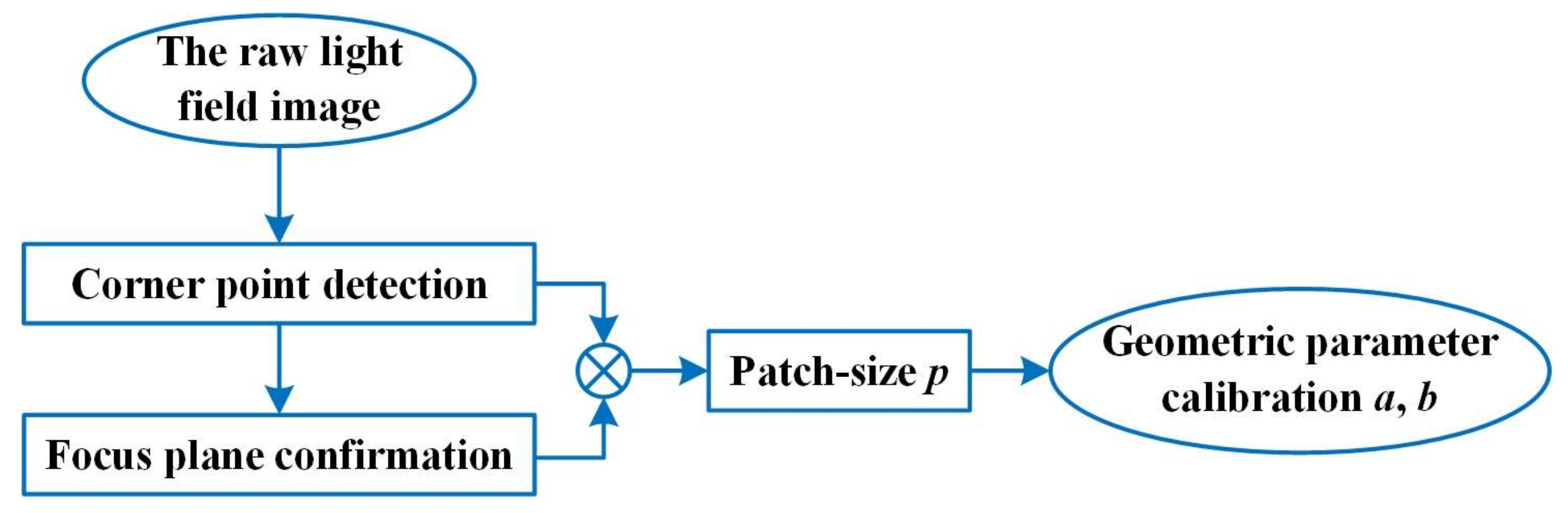
3. Calibration Method

3.1. Corner Detection Algorithm Based on ESIF

Since single microlens has such a small imaging range, the traditional corner detection methods, such as Harris operator [20] and Shi-Tomasi operator [21], are prone to missed or false detection in the raw light field image. The corner positions are difficult to accurately identify, which make it inconvenient to obtain the initial conditions. Therefore, we propose a corner detection algorithm based on ESIF to improve the corner detection accuracy as shown in Figure 4 and Algorithm 1.
The corner detection algorithm can be described in detail as follows:
Step1: extracting the ROI Oi of the light field raw image. Considering that the ROI Oi is the imaging region of the MLA for checkerboard corner, we adjust the two-dimensional mobile platform to align the checkerboard corner with the center of the main lens. During the movement of the precision motorized stage, the center region of the raw image of the light field can be taken as ROI.
Step2: detection checkerboard edge lines. A median filter algorithm is applied on the ROI to eliminate the imaging noise [22,23], and the Hough line detection algorithm is applied to each micro-image imaging region to obtain edge blocks [24].
Step3: obtaining edge blocks in different directions from the corner. In the ROI, the edge block Ai, Bi, Ci, Di are obtained with the edge lines as the center line.
Step4: extracting precise coordinates of the checkerboard corner. The row or column pixels in the edge block are fitted to find edge points ai, bi, ci, di with the largest derivative values, and the corner coordinates are calculated by the average value of the edge point coordinates. The precise corner coordinates in the raw corner image can be calculated by Equation (6).
x u i = 1 n 1 + n 4 [ 1 n 1 j = 1 n 1 x a i j + 1 n 4 j = 1 n 4 x d i j ] y u i = 1 n 2 + n 3 [ 1 n 2 j = 1 n 2 y b i j + 1 n 3 j = 1 n 3 y c i j ]
where ni represents the number of edge points in different edge block, xui and yui represent the abscissa and ordinate of corner in the ith micro-image, respectively. aij, bij, cij and dij are the jth edge points in the ith microlens, respectively. x a i j and x d i j are the abscissas of the edge points aij and dij, y b i j and y c i j denote the ordinates of the edge points bij and cij, respectively.
Therefore, the corner detection algorithm based on ESIF can accurately obtain the corner coordinate in the raw corner image, which creates better initial conditions for confirming the focus plane of the focused light field camera.
Algorithm 1: Automatic Corner Detection Method
Input:{Mi|∈[1, n]} Raw micro-image; n: the number of the micro-image;
Step 1Adjust the two-dimensional mobile platform, extract the ROI Oi from the raw corner image.
Step 2for each i∈[I, n] do
Raw micro-image; processing by median filter and Hough line detection algorithms;
if the number of lines equal to 4 then
Obtain edge line on each micro-image;
else
Break the loop;
Step 3Obtain edge block {Ai, Bi, Ci, Di};
Edge gray curve fitting and derivative;
Step 4Calculate the edge points {ai, bi, ci, di} from the edge block;
Obtain precise corner coordinate {ui};
Return precise corner coordinate;
Output:Precise corner coordinate in the raw corner image.

3.2. Focus Plane Confirmation

In Figure 5, we can observe that the corner size La will change from large to small and then larger when the object distances are changed. During the defocus-focus-defocus switching process, the field of view of focused light field camera will change as the object distance changes. The larger the field of view, the smaller the corner pixel size Lr and Ls. Therefore, we also need to design a double-checkerboard calibration board to confirm the focus plane. The double-checkerboard calibration board is mainly to make the difference results between the corner point size of the reference checkerboard and the standard checkerboard, and improve calculation accuracy of the corner positions.
The flow chart of focal plane confirmation is shown in Figure 6, and the symbol “⊗” represents the combination of the corner pixel size and the actual size of per-pixel to calculate the corner size. Firstly, the double- checkerboard calibration board is fixed to a precision motorized rail, and the focused light field camera is used to acquire calibration board images at different object distances. Then, the edge points are extracted by Step 3 in Section 3.1, and the horizontal (vertical) pixels sizes between the left and right (up and down) edge points are calculated in the double-checkerboard. The pixel size Lr of reference corner and pixel size Ls of standard corner can be represented by the horizontal (vertical) pixel size. Therefore, the actual size of per-pixel Lp is obtained by Equation (7).
L p = C r L r L s
where Cr is reference checkerboard corner size. The corner size La can be calculated by Equation (8).
L a = L p L s
Then the object distance u is expressed by Equation (9).
u = arg min L a ( u )

4. Experimental Analysis

4.1. Simulation Experiments

In this paper, we further proved the effectiveness and robustness of the calibration method on the Zemax software by comparing the differences between the real and calculated values. In the optical simulation experiments, the optical parameters were F = 35 mm, a = 15 mm, b = 3 mm and D/δ = 100. The object distance u which represents the distance between checkerboard image and the main lens in Zemax software was set to 230.91 mm, 267.77 mm, and 300 mm, respectively. The raw light field images were shown in Figure 7a, the central sub-aperture images were rendered by the raw light field image in Figure 7b,c was the yellow magnified areas of the rendered images.
The simulation experimental results of patch-size p at different object distances were shown in Table 1. pg was the ground truth of patch-size p at different focus distances, pc represented the simulation results of patch-size p by using the corner detection algorithm based on ESIF. Since the object distance was closer to the focal plane, the calibrated value pc was closer to pg, and the corner detection was more accurate. When the object distance f = 300 mm, the absolute error was 0.02 pixel and the relative error was 0.1%.
The patch-size p was substituted into Equations (1) and (4), and the calibrated parameters a and b were compared with the ground truth parameters as shown in Table 2. The results showed that the maximum absolute error ratio between the ground truth and the values derived by the proposed algorithm was only 0.083%, and the average error ratio was only 0.05%, and it demonstrated our method had high accuracy.
In addition, our method was also compared with Wang’s algorithm in the raw light field images [8], and the experiment results were listed in Table 3. Wang’s results were directly copied from his paper. Obviously, the error ratios calculated by our method were lower than Wang’s method, so it demonstrated our method was more accurate.

4.2. Physical Experiments

In this paper, a focused light field camera had been independently developed to be used in real scenes, and it mainly consisted of a main lens, connecting device, MLA and an image sensor, as shown in Figure 8a. The dimensions of the microlens array were 10 × 10 mm as well as array of 40 × 40. The resolution of the image sensor was 5120 × 5120 pixels, and the pixel pitch was 2.5 × 2.5 μm, and the CMOS sensor type was global shutter GMAX0505. The focal length F of the main lens was 35 mm, and the connecting device was used to fix the MLA as shown in Figure 8b.
The calibration system for the focused light field camera was set up and mainly consisted of our light field camera, precision motorized stage, calibration board and two-dimensional stage as shown in Figure 9a. The double-checkerboard calibration board consisted of a reference checkerboard as shown in Figure 9b,c was shown the standard checkerboard. Among them, the corner size Cs of standard checkerboard was 0 mm. When the checkerboard calibration board was moved with the precision electric table, the smaller the actual value of the reference checkerboard corner size Cr is, and the greater impact on the calculation accuracy represented by the actual size of per-pixel Lp. Therefore, the corner size Cr was set to 0.1 mm.
A double-checkerboard calibration board was moved with 1 mm each step, and the corner pixel sizes Lr and Ls were shown in Figure 10a. The corner size La was changed with the moving distances of the precision motorized stage as shown in the Figure 10b. The object plane corresponding to the minimum corner point La was the focal plane of our light field camera.
After the focal plane position was determined, the corner coordinates of the checkerboard were calculated by using our proposed method in the raw light field image, and the corner detection results were shown in Figure 11.
In Figure 11, uij was the corner coordinates of the checkerboard, and Mij was the center coordinates of the MLA. Their results were as follows:
u i j = ( 42.48 , 43 . 89 ) ( 161 . 53 , 43 . 37 ) ( 279 . 53 , 44 . 50 ) ( 42 . 52 , 162 . 72 ) ( 160 . 51 , 162 . 59 ) ( 278 . 48 , 163 . 33 ) ( 41 . 49 , 280 . 08 ) ( 160 . 51 , 280 . 82 ) ( 278 . 50 , 280 . 68 )
M i j = ( 50 , 55 ) ( 156 , 55 ) ( 262 , 55 ) ( 50 , 161 ) ( 156 , 161 ) ( 262 , 161 ) ( 50 , 267 ) ( 156 , 267 ) ( 262 , 267 )
The designed values and calibration results of the geometric parameters of our light field camera were shown in Table 4. The calibration results of a and b were 18.53 mm and 2.89 mm, respectively. Since the thickness influence of the MLA and the installation error, there was a slight difference between the designed value and calibration results. Since the ground truth was unknown, it made it impossible to analyze the calibration parameters from the calibration results.
Moreover, the real objects (letters and Rubik’s cube) were rendered by using the calibration results and the design values to verify the calibration accuracy, respectively. Figure 12a showed the rectified rendered image of the real object by using the calibration parameters, and Figure 12c showed the initial rendered images of the real objects by using the designed parameters. From Figure 12a,c, especially from the enlarged area in Figure 12b,d, it could be seen that the rendered images were smoother by directly using our calibration method, and the rendered images were filled with artifacts by using the designed values. Therefore, our method was very effective for the geometric parameters calibration of the focused light field cameras, and it could greatly improve the application ability of focusing light field cameras in other fields.

5. Conclusions

The traditional geometric parameter calibration methods of light field camera did not fully utilize light field data, and they were highly dependent on prior parameters, and required a large amount of calculation and had weak adaptability, which resulted in low calibration accuracy and consequently were difficult to be widely used. In this paper, we propose a new method based on ESIF to accurately calibrate geometric parameters for focused light field cameras. Compared with other traditional works on the calibration of focused light field cameras, our method can accurately confirm the focal plane of focused light field cameras, and it detects the corner coordinates on the raw light field image and derives the geometric relationship between the calibration parameters combined with the light path of focused light field imaging. The error between the calibration result and ground truth was 0.083% in the simulation experiment, and it had shown that our calibration method had better accuracy. The real physical results also showed that the proposed calibration algorithm was effective and reliability.
Of course, our method has some shortcomings. The Zemax simulation experiments are completed under ideal conditions, but the calibration accuracy decreases due to increasing lens distortion, vignetting as well as geometric distortions from the raw microlens images in physical experiments, and all these factors affect the feature detection. We will take these factors into account in research and applications in the future.

Author Contributions

Conceptualization, W.F.; writing, H.W.; validation, H.W. and J.F.; supervision, B.X. and X.W.; funding acquisition, W.F. All authors have read and agreed to the published version of the manuscript.

Funding

This research was funded by National Natural Science Foundation of China (Grant No. 51805153), China Postdoctoral Science Foundation (Grant No. 2022M711822).

Institutional Review Board Statement

Not applicable.

Informed Consent Statement

Not applicable.

Data Availability Statement

Data underlying the results presented in this paper are not publicly available at this time but maybe obtained from the authors upon reasonable request.

Conflicts of Interest

The authors declare no conflict of interest.

References

  1. Zhu, Z.; Zhao, Y.; Liu, S.; Liu, Y.; Wang, W.; Tang, L. Calibration of line-structured light vision sensors based on simultaneous polarization imaging. Meas. Sci. Technol. 2022, 33, 115202. [Google Scholar] [CrossRef]
  2. Schambach, M.; León, F.P. Microlens array grid estimation, light field decoding, and calibration. IEEE Trans. Comput. Imaging 2020, 6, 591–603. [Google Scholar] [CrossRef]
  3. Hu, Y.; Yao, M.; Huang, Z.; Peng, J.; Zhang, Z.; Zhong, J. Full-Resolution Light-Field Camera via Fourier Dual Photography. Photonics 2022, 9, 559. [Google Scholar] [CrossRef]
  4. Lam, E.Y. Computational photography with plenoptic camera and light field capture: Tutorial. J. Opt. Soc. Am. A 2015, 32, 2021–2032. [Google Scholar] [CrossRef]
  5. Bok, Y.; Jeon, H.-G.; Kweon, I.S. Geometric Calibration of Micro-Lens-Based Light Field Cameras Using Line Features. IEEE Trans. Pattern Anal. Mach. Intell. 2017, 39, 287–300. [Google Scholar] [CrossRef]
  6. Labussière, M.; Teulière, C.; Bernardin, F.; Ait-Aider, O. Leveraging Blur Information for Plenoptic Camera Calibration. Int. J. Comput. Vis. 2022, 130, 1655–1677. [Google Scholar] [CrossRef]
  7. Liu, Y.; Mo, F.; Aleksandrov, M.; Zlatanova, S.; Tao, P. Accurate calibration of standard plenoptic cameras using corner features from raw images. Opt. Express 2021, 29, 158–169. [Google Scholar] [CrossRef]
  8. Wang, Y.; Qiu, J.; Liu, C.; He, D.; Kang, X.; Li, J.; Shi, L. Virtual Image Points Based Geometrical Parameters’ Calibration for Focused Light Field Camera. IEEE Access 2018, 6, 71317–71326. [Google Scholar] [CrossRef]
  9. Jin, X.; Sun, X.; Li, C. Geometry parameter calibration for focused plenoptic cameras. Opt. Express 2020, 28, 3428–3441. [Google Scholar] [CrossRef]
  10. Cai, Z.; Liu, X.; Pedrini, G.; Osten, W.; Peng, X. Light-field depth estimation considering plenoptic imaging distortion. Opt. Express 2020, 28, 4156–4168. [Google Scholar] [CrossRef]
  11. Mishiba, K. Fast Depth Estimation for Light Field Cameras. IEEE Trans. Image Process. 2020, 29, 4232–4242. [Google Scholar] [CrossRef]
  12. Cai, L.; Luo, P.; Zhou, G.; Chen, Z. Maneuvering target recognition method based on multi-perspective light field reconstruction. Int. J. Distrib. Sens. Netw. 2019, 15, 1–12. [Google Scholar] [CrossRef]
  13. Guan, Y.; Sang, X.; Xing, S.; Chen, Y.; Li, Y.; Chen, D.; Yu, X.; Yan, B. Parallel multi-view polygon rasterization for 3D light field display. Opt. Express 2020, 28, 34406–34421. [Google Scholar] [CrossRef]
  14. Zhu, S.; Lai, A.; Eaton, K.; Jin, P.; Gao, L. On the fundamental comparison between unfocused and focused light field cameras. Appl. Opt. 2018, 57, A1–A11. [Google Scholar] [CrossRef]
  15. Cai, Z.; Liu, X.; Pedrini, G.; Osten, W.; Peng, X. Unfocused plenoptic metric modeling and calibration. Opt. Express 2019, 27, 20177–20198. [Google Scholar] [CrossRef]
  16. Ueno, R.; Suzuki, K.; Kobayashi, M.; Kwon, H.; Honda, H.; Funaki, H. Compound-Eye Camera Module as Small as 8.5 × 8.5 × 6.0 mm for 26 k-Resolution Depth Map and 2-Mpix 2D Imaging. IEEE Photon. J. 2013, 5, 6801212. [Google Scholar] [CrossRef]
  17. Georgiev, T.; Lumsdaine, A. Focused plenoptic camera and rendering. J. Electron. Imaging 2010, 19, 021106. [Google Scholar]
  18. Chlubna, T.; Milet, T.; Zemčík, P. Real-time per-pixel focusing method for light field rendering. Comput. Vis. Media 2021, 7, 319–333. [Google Scholar] [CrossRef]
  19. Tian, Y.; Liu, B.; Su, X.; Wang, L.; Li, K. Underwater Imaging Based on LF and Polarization. IEEE Photon. J. 2018, 11, 1–9. [Google Scholar] [CrossRef]
  20. Sipiran, I.; Bustos, B. Harris 3D: A robust extension of the Harris operator for interest point detection on 3D meshes. Vis. Comput. 2011, 27, 963–976. [Google Scholar] [CrossRef]
  21. Mu, Z.; Li, Z. A Novel Shi-Tomasi Corner Detection Algorithm Based on Progressive Probabilistic Hough Transform. In Proceedings of the Chinese Automation Congress (CAC), Xi’an, China, 30 November–2 December 2018; pp. 2918–2922. [Google Scholar] [CrossRef]
  22. Chen, Y.; Zu, S.; Wang, Y.; Chen, X. Deblending of simultaneous source data using a structure-oriented space-varying median filter. Geophys. J. Int. 2020, 222, 1805–1823. [Google Scholar] [CrossRef]
  23. Feng, Z.; He, W.; Fang, J.; Gu, G.; Chen, Q.; Zhang, P.; Chen, Y.; Zhou, B.; Zhou, M. Fast Depth Imaging Denoising With the Temporal Correlation of Photons. IEEE Photon. J. 2017, 9, 1–10. [Google Scholar] [CrossRef]
  24. Boudraa, O.; Hidouci, W.K.; Michelucci, D. Using skeleton and Hough transform variant to correct skew in historical documents. Math. Comput. Simul. 2020, 167, 389–403. [Google Scholar] [CrossRef]
Figure 1. Imaging model of focused light field camera.
Photonics 10 00187 g001
Figure 2. The rendering of focused light field imaging.
Photonics 10 00187 g002
Figure 3. Calibration flow of geometric parameter for focused light field camera.
Photonics 10 00187 g003
Figure 4. The flow diagram of the corner detection algorithm.
Photonics 10 00187 g004
Figure 5. The defocus-focus-defocus switching process.
Photonics 10 00187 g005
Figure 6. The flow diagram of the focus plane confirmation.
Photonics 10 00187 g006
Figure 7. Simulation experiments. (a) The raw light field images, (b) the rendered images and (c) the yellow magnified areas of the rendered images.
Photonics 10 00187 g007
Figure 8. Self-made focused light field camera. (a) Hardware structure, (b) microlens array and its connecting device.
Photonics 10 00187 g008
Figure 9. Calibration system of light field camera. (a) Hardware implement, (b) reference checkerboard, (c) standard checkerboard.
Photonics 10 00187 g009
Figure 10. Focus plane confirmation. (a) Corner pixel size measured with the change in different object distances, (b) corner size measured with the change in different object distances.
Photonics 10 00187 g010
Figure 11. Corner detection results of the raw light field image.
Photonics 10 00187 g011
Figure 12. Rendered images of the actual scene. (a) The calibration parameters; (b) magnification of green box in (a); (c) the designed parameters; (d) magnification of green box in (c).
Photonics 10 00187 g012
Table 1. Accuracy comparison of patch-size p.
Object Distance (mm)pg (Pixel)pc (Pixel)Absolute Error (mm)Error Ratio
230.912323.100.100.4348%
267.772121.030.030.1429%
3002019.980.020.1000%
Table 2. Accuracy comparison of a and b.
ParametersGround Truth (mm)Calibration (mm)Absolute Error (mm)Error Ratio
aag = 15.0000ac = 15.01250.01250.083%
bbg = 3.0000bc = 2.99950.00050.017%
Table 3. Comparison results with different methods.
ParametersGround Truth (mm)Wang’s Results (mm)Wang’s Error RatioOurs Method (mm)Ours Error Ratio
a−0.6649−0.73139.99%−0.62236.41%
b0.13820.13830.07%0.13631.37%
Average error ratio 5.03% 3.89%
Table 4. Calibration results of geometric parameters.
ParametersDesigned ValuesCalibration Results
a15.00 mm18.53 mm
b3.00 mm2.89 mm
Disclaimer/Publisher’s Note: The statements, opinions and data contained in all publications are solely those of the individual author(s) and contributor(s) and not of MDPI and/or the editor(s). MDPI and/or the editor(s) disclaim responsibility for any injury to people or property resulting from any ideas, methods, instructions or products referred to in the content.

