Communication

Plasmonic Generation of Spatiotemporal Optical Vortices

by
Artem I. Kashapov
1,2,*,
Evgeni A. Bezus
1,2,
Dmitry A. Bykov
1,2 and
Leonid L. Doskolovich
1,2
1
Image Processing Systems Institute—Branch of the Federal Scientific Research Centre “Crystallography and Photonics” of Russian Academy of Sciences, 151 Molodogvardeyskaya st., 443001 Samara, Russia
2
Samara National Research University, 34 Moskovskoye Shosse, 443086 Samara, Russia
*
Author to whom correspondence should be addressed.
Photonics 2023, 10(2), 109; https://doi.org/10.3390/photonics10020109
Submission received: 16 December 2022 / Revised: 12 January 2023 / Accepted: 17 January 2023 / Published: 20 January 2023
(This article belongs to the Special Issue Light Focusing and Optical Vortices)

Abstract

:
We investigate the transformation of spatiotemporal optical signals using the Kretschmann configuration with an additional dielectric layer, which can be referred to as the “generalized Kretschmann setup”. We demonstrate that in the considered structure, it is possible to achieve the condition of generating a reflected optical pulse containing a spatiotemporal optical vortex, which appears to be impossible in the conventional Kretschmann configuration. High-quality generation of spatiotemporal optical vortices using the investigated structure was confirmed by the results of rigorous numerical simulations. The obtained results are promising for applications in analog optical computing and optical information processing systems.

1. Introduction

An optical vortex (OV) beam is a special type of optical beams comprising a zero in the field amplitude and a discontinuity in the azimuthal phase. The most common type of optical vortex beams corresponds to a beam with a phase singularity in the plane perpendicular to the direction of beam propagation. Such a beam possesses orbital angular momentum (OAM) and is characterized by a rotational flow of energy density around the phase singularity. OAM beams and the methods of their generation using various diffractive structures and metasurfaces have been extensively studied [1,2,3,4,5,6,7,8,9] and have many promising applications, including optical trapping [5,6], super resolution microscopy [7], and free-space telecommunications [8,9], among others.
Over the past few years, optical pulses possessing optical vortices in the spatiotemporal domain (the so-called spatiotemporal optical vortices, STOVs) have become the subject of intensive research [10,11,12,13,14,15]. It is believed that STOVs will give a new degree of freedom for various applications of the OV beams in optical trapping and telecommunications. However, the generation of STOVs remains one of the standing challenges. In [10,12,15,16], for the generation of STOVs, complex optical setups are used, which include a spatial light modulator (or a phase diffractive element), a diffraction grating, and several lenses and mirrors.
In recent work [17], to generate an STOV, it was proposed that using a much simpler and compact structure consisting of a subwavelength diffraction grating with an asymmetrical unit cell optically implementing the operation of spatiotemporal differentiation of the incident pulse envelope in transmission (i.e., computing a sum of first-order spatial and temporal derivatives of the envelope). In general, the transformation of an optical pulse by a photonic structure can be described in terms of the theory of linear systems. In this approach, the pulse transformation is considered as a transformation by a linear system, the transfer function (TF) of which is proportional to the transmission (or reflection) coefficient of the structure, depending on the angular and/or spatial frequency [18,19,20,21]. The TF of an exact differentiator vanishes at the central angular and spatial frequencies; therefore, a zero in the transmission or reflection spectrum of the diffractive structure is required for performing optical differentiation. As a rule, reflection (transmission) zeros arise due to the resonant excitation of the eigenmodes of the structure; hence, resonant photonic structures, including diffraction gratings (photonic crystal slabs) [18,19,20,22,23,24], multilayer structures, and their integrated counterparts [21,25,26,27,28,29] are used for optical differentiation. In [17], the spatiotemporal differentiation and the generation of an STOV are provided by tailoring the geometry of the asymmetrical unit cell of the grating, ensuring the zero transmission at the central pulse frequency and the required π/2 phase difference between the linear terms of the Taylor series expansion of the grating transmission coefficient.
The grating-based differentiator in [17] provides the generation of STOVs in transmission. The possibility of generating STOVs in reflection is also of considerable interest. One of the simplest structures that can be used for spatiotemporal optical differentiation in reflection is the so-called Kretschmann configuration, consisting of a dielectric prism with a metal layer deposited on its surface [28,30]. This structure is lithography-free and, therefore, is significantly simpler in terms of fabrication, as compared to the grating-based differentiator in [17]. In the reflection spectrum of this structure, one can observe a resonant reflection dip associated with the excitation of a surface plasmon polariton (SPP) at the “outer” interface of the metal film. Note that a reflection zero in such a structure required for implementing the differentiation operation can be achieved when the so-called critical coupling condition is met [28].
In the present work, we investigate the generation of STOVs in a “generalized” Kretschmann setup containing an additional dielectric layer deposited on the “outer” side of the metal layer. The presented numerical simulation results show that the spatiotemporal differentiator based on the generalized Kretschmann setup enables the generation of an STOV with high quality. At the same time, the condition of π/2 phase difference between the coefficients at the first-order Taylor series terms of the TF, which is required for the STOV generation, is, as it appears, not fulfilled in the conventional Kretschmann setup without an additional dielectric layer.

2. Theoretical Description of the Generation of a Spatiotemporal Optical Vortex

Let us first consider the transformation of a two-dimensional optical pulse by a layered diffractive structure in reflection. Let the incident pulse have a central frequency ω = ω 0 and impinge on the structure at an angle of incidence θ 0 (Figure 1). We denote by G ( k x , inc ,   ω inc ) , the spatiotemporal spectrum of the incident pulse envelope E inc ( x inc , t ) defined in the coordinate system ( x inc ,   z inc ) associated with the incident pulse. This spectrum represents the amplitudes of the plane waves constituting the pulse and having the spatial frequencies (transverse wave vector components) k x , inc (in the coordinate system ( x inc ,   z inc ) ) and the angular frequencies ω inc + ω 0 [29]. When the pulse is reflected from the structure, the plane wave amplitudes G ( k x , inc ,   ω inc ) are multiplied by the reflection coefficient of this structure R ( k x ,   ω inc + ω 0 ) , where k x denotes the in-plane component (x component) of the wave vector of the plane wave in the “global” coordinate system ( x ,   z ) (see Figure 1):
k x = k x , inc cos θ 0 k z , inc sin θ 0 = k x , inc cos θ 0 + sin θ 0 ( ω inc + ω 0 v ) 2 k x , inc 2 ,
where v is the phase velocity in the superstrate region. Using the theory of linear systems, it can be easily shown that the transformation of the spatiotemporal envelope E inc ( x inc , t ) E refl ( x refl , t ) of the incident pulse occurring upon its reflection from the structure (see Figure 1) can be described as the transformation of the signal E inc ( x inc , t ) by a linear system having the following transfer function [29]:
H st ( k x , inc , ω inc ) = R ( k x , ω inc + ω 0 ) = R ( k x , inc cos θ 0 + sin θ 0 ( ω inc + ω 0 v ) 2 k x , inc 2 , ω inc + ω 0 ) .
If a diffractive structure possesses a reflection zero at k x = k x , 0 and ω = ω 0 (i.e., at k x , inc = 0 and ω inc = 0 ), the TF of Equation (2) can be written as [29,30]:
H st ( k x , inc , ω inc ) = c x , 1 k x , inc + c t , 1 ω inc + O [ k x , inc 2 + ω inc 2 ] .
The linear terms in the right-hand side of Equation (3) are proportional to the TFs of exact differentiators with respect to a spatial variable ( H id , s ( k x , inc ) = i k x , inc ) and to time ( H id , t ( ω inc ) = i ω inc ). Therefore, the structure with the TF of Equation (3) performs the computation of the following first-order spatiotemporal differential operator [29]:
E refl ( x inc , t ) = i c x , 1 E inc ( x inc , t ) x inc + i c t , 1 E inc ( x inc , t ) t .
Let us now consider the generation of a spatiotemporal OV. Following [17], we suppose that the incident optical pulse has a Gaussian envelope in the coordinate system ( x inc , z inc ) associated with it (see Figure 1):
E inc ( x inc , t ) = exp ( x inc 2 / σ x 2 t 2 / σ t 2 ) .
Note that in this case, the envelope spectrum is also described by a Gaussian function [29]:
G ( k x , inc , ω inc ) = σ x σ t 4 π exp ( σ x 2 k x , inc 2 4 σ t 2 ω inc 2 4 ) .
Substituting Equation (5) into Equation (4), we obtain:
E refl ( x inc , t ) = 2 i ( c x , 1 σ x 2 x inc c t , 1 σ t 2 t ) exp ( x inc 2 σ x 2 t 2 σ t 2 ) .
From Equation (7), it follows that if ψ = arg ( c x , 1 / c t , 1 ) = ± π / 2 and | c t , 1 σ x | / | c x , 1 σ t | = 1 , then in normalized coordinates x ˜ = x refl / σ x , t ˜ = t / σ t , the spatiotemporal profile of the reflected pulse envelope contains an OV:
E refl ( x ˜ , t ˜ ) = 2 i c x , 1 σ x ( x ˜ ± i t ˜ ) exp ( x ˜ 2 t ˜ 2 ) .

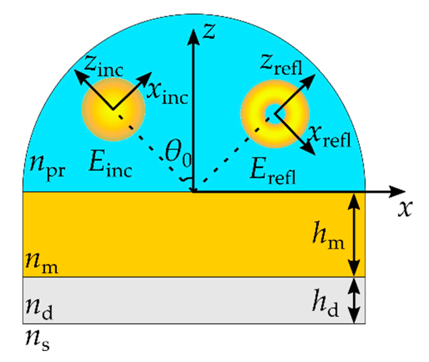
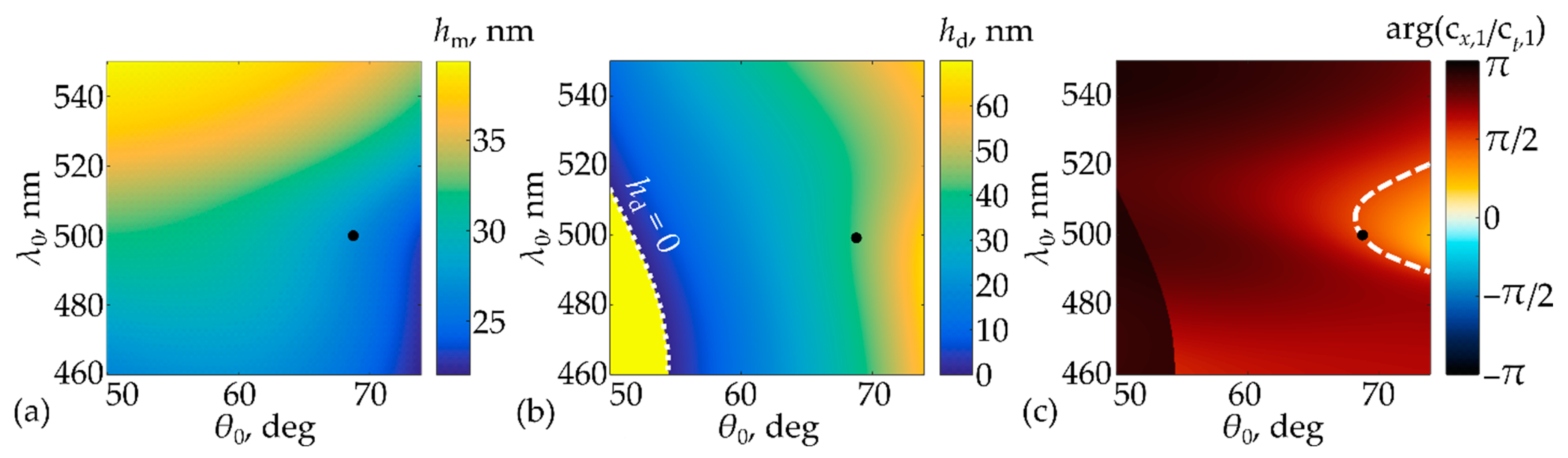
3. Geometry of the Generalized Kretschmann Setup and the Zero Reflection Condition

Figure 1 shows a schematic illustration of the considered generalized Kretschmann setup consisting of a prism with refractive index n pr , a metal layer with thickness h m and refractive index n m , and a dielectric layer with thickness h d and refractive index n d . The structure is surrounded by a medium with refractive index n s .
To describe the optical properties of the structure, let us consider a plane wave with unit amplitude, free-space wavelength λ , and a fixed linear polarization (for the examples considered below, TM-polarization) impinging on the structure at an angle of incidence θ 0 . We assume that the incidence angle meets the inequality θ 0 θ min = arcsin ( n med / n pr ) , i.e., the wave undergoes total internal reflection at the bottom interface of the structure. In this case, the reflection coefficient at this interface has the form ρ = e i φ , so that | ρ | = 1 . Using the multiple-wave interference model, the reflection coefficient of the structure can be easily obtained as [31]:
R ( h m , h d , λ , θ 0 ) = r 1 e 2 i k z h d e i φ ( r 1 r 2 t 2 ) 1 r 2 e i φ e 2 i k z h d ,
where r 1 = r 1 ( h m , λ , θ 0 ) and r 2 = r 2 ( h m , λ , θ 0 ) are the complex reflection coefficients of the metal layer for waves incident on this layer from above (from the prism) and from below (from the dielectric layer), respectively, t = t ( h m , λ , θ 0 ) is the complex transmission coefficient of the metal layer, k z ( λ , θ 0 ) = ( k 0 n d ) 2 k x 2 is the magnitude of the z component of the wave vector inside the dielectric layer, and k 0 = 2 π / λ is the wave number.
Following [31], one can see that the reflection coefficient defined by Equation (9) can strictly vanish. This can be achieved by a proper choice of the thicknesses of the metal ( h m ) and dielectric ( h d ) layers. By equating the numerator of the reflection coefficient of Equation (9) to zero, we obtain:
r 1 r 1 r 2 t 2 = e 2 i k z h d e i φ .
Consider the left-hand side of Equation (10) as a function of the thickness of the metal layer h m :
f ( h m ) = r 1 ( h m ) r 1 ( h m ) r 2 ( h m ) t 2 ( h m ) .
As follows from Equations (10) and (11), the necessary condition for achieving a zero reflection imposed on the thickness of the metal layer, h m , is | f ( h m ) | = 1 . Considering the limiting cases h m 0 and h m , at which | f ( 0 ) | = | r 1 ( 0 ) | < 1 and | f ( ) | = | 1 / r 2 ( ) | > 1 , respectively, one can conclude that a solution of the equation | f ( h m ) | = 1 always exists [27]. Next, by equating the arguments of the left-hand and right-hand sides of Equation (10), we get an expression for the thickness of the dielectric layer h d , providing zero reflection at the found thickness of the metal layer h m :
h d = 1 2 k z ( 2 π n + arg f ( h m , 1 ) ) ,   n .

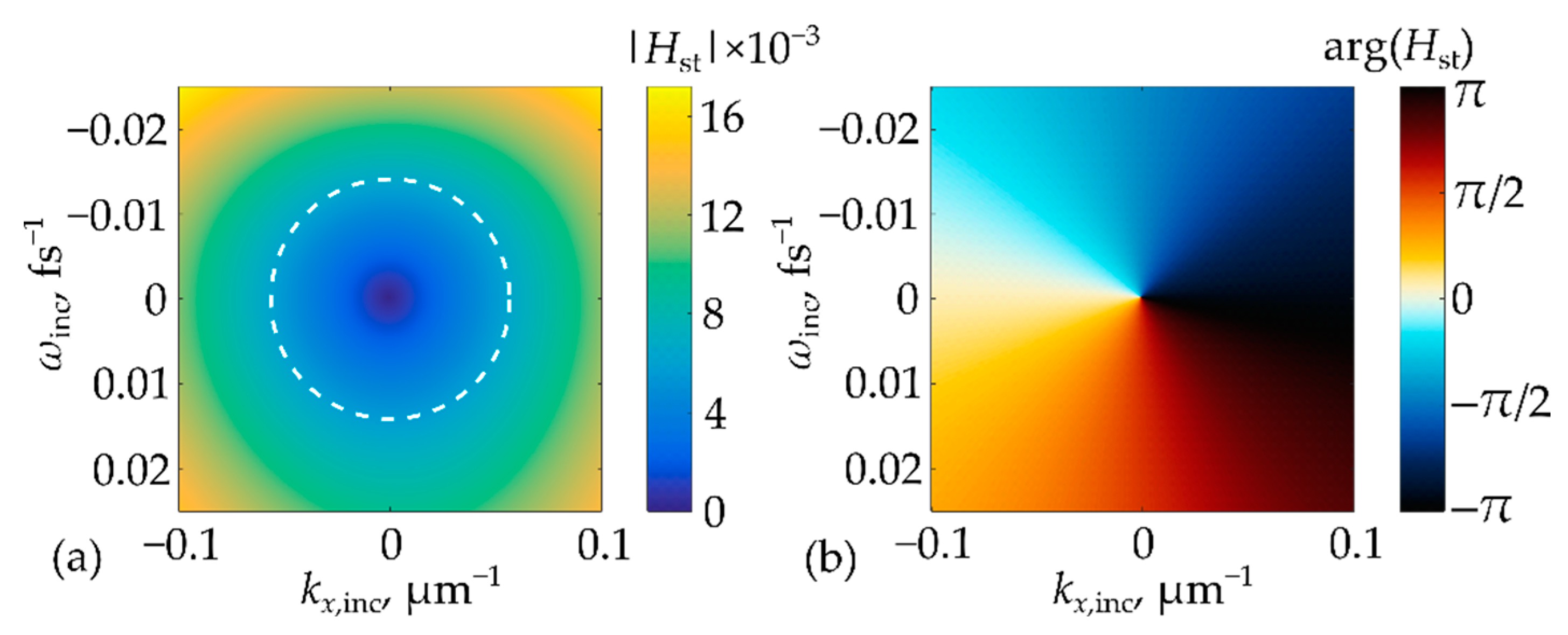
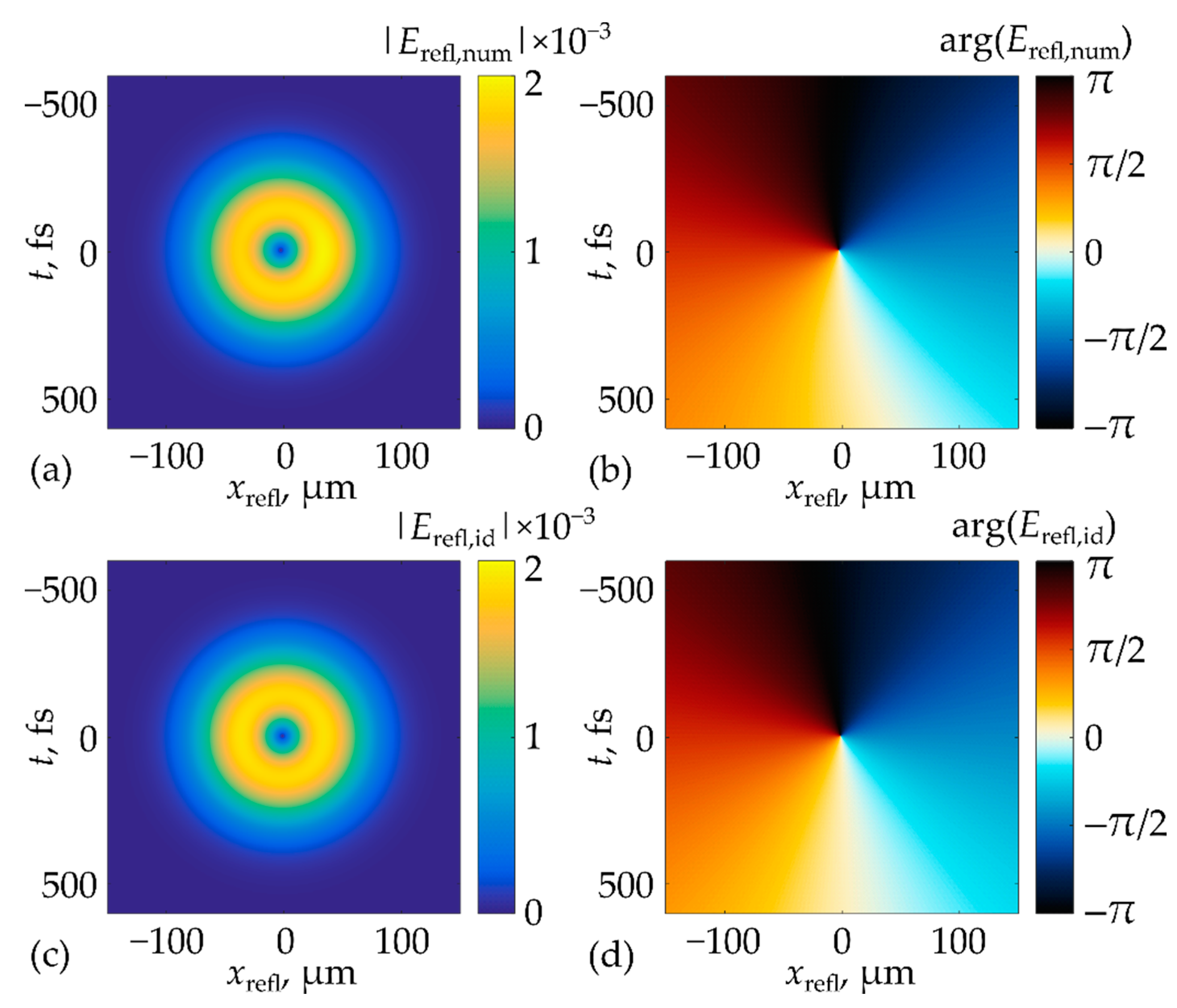
4. Results and Discussion

4.1. Numerical Investigation of the Generalized Kretschmann Setup with a Reflection Zero

Using the zero reflection conditions derived above, we calculated the structures with the following parameters. As the materials of the metal and dielectric layers, gold (Au) and silicon dioxide (SiO2) were considered, respectively. The prism material was assumed to be BK7 glass, and the refractive index of the surrounding medium was set to n s = 1 . The refractive indices for the other materials (Au, SiO2, BK7) were taken from [32]. Here, and in what follows, the wavelength dispersion of the refractive indices was taken into account for all materials. Figure 2a,b show the calculated thicknesses of the metal (Figure 2a) and dielectric (Figure 2b) layers of the structure providing zero reflection for the given values of wavelength λ 0 and angle of incidence θ 0 (see Equations (10)–(12)). Note that in the considered case, the minimum value of the angle of incidence θ 0 , providing total internal reflection at the bottom interface of the structure, is θ min = 41.09 ° . Figure 2c shows the phase (argument) difference ψ = arg ( c x , 1 / c t , 1 ) of the expansion coefficients of the TF of Equation (3), rigorously calculated for each of these structures for the incident TM-polarized waves. To calculate this phase difference, we used the following approach. According to Equation (2), the TF is proportional to the complex reflection coefficient of the structure, which was calculated for the structures corresponding to each point in Figure 2c (i.e., for each pair of layer thicknesses h m and h d obtained from the data presented in Figure 2a,b, respectively) using an in-house implementation of the enhanced transmittance matrix approach [33]. Then, the coefficients c x , 1 and c t , 1 were calculated from the TF using the numerical differentiation formulas. It can be seen from Figure 2c that in the given parameter space ( λ 0 , θ 0 ), there exists a line (the white dashed line in Figure 2c), along which the ratio ψ = arg ( c x , 1 / c t , 1 ) satisfies the condition for the STOV generation ψ = π / 2 .
It is important to note that Figure 2b,c show the impossibility of achieving the condition of the STOV generation by the structure with the considered parameters corresponding to the conventional Kretschmann configuration. Indeed, the conventional Kretschmann configuration corresponds to the vanishing thickness of the additional dielectric layer ( h d = 0 ). This condition is shown by the white dotted line in Figure 2b. From the comparison of Figure 2b,c, it is clear that the curves corresponding to the conditions h d = 0 and ψ = π / 2 do not intersect in the parameter space. In addition, it is worth mentioning that the further analysis of the conventional Kretschmann setup (not presented here for the sake of brevity) performed with other metals (Ag, Al, Cu) demonstrated that the STOV generation condition ψ = ± π / 2 also cannot be achieved. At the same time, the introduction of the additional dielectric layer might make it possible to achieve the required ± π / 2 phase difference (however, the use of different materials of the prism and/or the dielectric layer may be required). For example, if copper (Cu) is used as the material of the metal layer, STOV generation conditions can be fulfilled for certain wavelengths from the violet, green, and yellow parts of the visible spectrum provided that SF11 and Al2O3 are used as the materials of the prism and dielectric layer, respectively.

4.2. Numerical Demonstration of the STOV Generation

Let us demonstrate the generation of a spatiotemporal OV by the investigated structure. According to Figure 2c, we chose a structure providing zero reflection and the required argument difference ψ = π / 2 at λ 0 = 500   nm and θ 0 = 68.66 ° for the incident TM-polarized wave (the corresponding point is shown with bold black dots in Figure 2a–c; in Figure 2c, this point is lying on the dashed white curve corresponding to the condition ψ = π / 2 ). At this point, the thicknesses of the metal and dielectric layers of the structure amount to 27.2 nm and 41.7 nm, respectively. At the specified central wavelength λ 0 , the refractive indices of the materials used in the calculations are n pr = 1.5214 (BK7 glass), n m = 0.9707 + 1.8562 i (Au), and n d = 1.4623 (SiO2).
Figure 3a,b show the amplitude (absolute value) and phase (argument) of the TF of the specified structure. As was mentioned above, the TF is proportional to the reflection coefficient of the structure and was calculated using the enhanced transmittance matrix approach [33]. In the vicinity of the reflection zero, the obtained TF is well described by the “main” (linear) part of Equation (3) at c x , 1 = 0.11 × e 3.32 i and c t , 1 = 0.43 × e ( 3.32 π / 2 ) i . These coefficients were found by fitting using the central finite-difference formulas. The white dashed circle in Figure 3a shows the 1 / e 2 level of the spectrum of the incident spatiotemporal Gaussian pulse of Equations (5) and (6) with σ x = 50   μ m and σ t = 200   fs used in the further simulations.
Figure 4a,b show the amplitude and phase of the spatiotemporal envelope of the pulse reflected from the structure. The reflected pulse envelope was calculated numerically using the rigorous linear system approach [29], describing the transformation of the incident spatiotemporal optical signal by a linear system with the TF of Figure 3. For the sake of comparison, Figure 4c,d shows the amplitude and phase of the “model” spatiotemporal envelope of Equation (7) calculated at the c x , 1 and c t , 1 values presented above. It is important to note that in the considered case, the normalized RMS deviation of the rigorously computed envelope (Figure 4a) from the model one (Figure 4c) is only 0.9%, which indicates the high quality of the STOV generation.

5. Conclusions

In the present work, we demonstrated the possibility of high-quality generation of spatiotemporal optical pulses possessing a phase singularity in the spatiotemporal domain (a spatiotemporal optical vortex) using the generalized Kretschmann setup containing an additional dielectric layer. From the presented results, it follows that the dielectric layer enables achieving conditions of the STOV generation, which, at least for the considered example, cannot be fulfilled in the case of the conventional Kretschmann geometry. The results of rigorous numerical simulations demonstrate the capability of generating a high-quality spatiotemporal optical vortex in reflection (the normalized root-mean-square error of the rigorously computed envelope from the model STOV does not exceed 1%). The obtained results may find use in the design of systems for analog optical computing and optical data processing.

Author Contributions

Conceptualization, L.L.D. and E.A.B.; methodology, L.L.D., D.A.B. and E.A.B.; software, A.I.K.; validation, A.I.K., E.A.B. and D.A.B.; formal analysis, A.I.K., E.A.B., D.A.B. and L.L.D.; investigation, A.I.K.; writing—original draft preparation, A.I.K., E.A.B. and L.L.D.; writing—review and editing, A.I.K., E.A.B., D.A.B. and L.L.D.; visualization, A.I.K.; supervision, L.L.D.; project administration, L.L.D.; funding acquisition, L.L.D. All authors have read and agreed to the published version of the manuscript.

Funding

This work was funded by Russian Science Foundation (Project No. 19-19-00514; investigation of the plasmonic generation of spatiotemporal optical vortices) and by Ministry of Science and Higher Education of the Russian Federation (state assignment to the FSRC Crystallography and Photonics RAS; development of the software for simulating the diffraction of a spatiotemporal optical signal).

Institutional Review Board Statement

Not applicable.

Informed Consent Statement

Not applicable.

Data Availability Statement

The data that support the presented results are available from the corresponding author upon reasonable request.

Conflicts of Interest

The authors declare no conflict of interest.

References

  1. Shen, Y.; Wang, X.; Xie, Z.; Min, C.; Fu, X.; Liu, Q.; Gong, M.; Yuan, X. Optical vortices 30 years on: OAM manipulation from topological charge to multiple singularities. Light Sci. Appl. 2019, 8, 90. [Google Scholar] [CrossRef] [PubMed] [Green Version]
  2. Kotlyar, V.V.; Kovalev, A.A.; Porfirev, A.P. Vortex Laser Beams, 1st ed.; CRC Press: Boca Raton, FL, USA, 2018. [Google Scholar]
  3. Lian, Y.; Qi, X.; Wang, Y.; Bai, Z.; Wang, Y.; Lu, Z. OAM beam generation in space and its applications: A review. Opt. Lasers Eng. 2022, 151, 106923. [Google Scholar] [CrossRef]
  4. Kotlyar, V.V.; Almazov, A.A.; Khonina, S.N.; Soifer, V.A.; Elfstrom, H.; Turunen, J. Generation of phase singularity through diffracting a plane or Gaussian beam by a spiral phase plate. J. Opt. Soc. Am. A 2005, 22, 849–861. [Google Scholar] [CrossRef] [PubMed]
  5. He, H.; Friese, M.E.J.; Heckenberg, N.R.; Rubinsztein-Dunlop, H. Direct observation of transfer of angular momentum to absorptive particles from a laser beam with a phase singularity. Phys. Rev. Lett. 1995, 75, 826–829. [Google Scholar] [CrossRef] [Green Version]
  6. Ng, J.; Lin, Z.; Chan, C.T. Theory of Optical Trapping by an Optical Vortex Beam. Phys. Rev. Lett. 2010, 104, 103601. [Google Scholar] [CrossRef] [Green Version]
  7. Heffernan, B.M.; Meyer, S.A.; Restrepo, D.; Siemens, M.E.; Gibson, E.A.; Gopinath, J.T. A fiber-coupled stimulated emission depletion microscope for bend-insensitive through-fiber imaging. Sci. Rep. 2019, 9, 11137. [Google Scholar] [CrossRef] [Green Version]
  8. Tyler, G.A.; Boyd, R.W. Influence of atmospheric turbulence on the propagation of quantum states of light carrying orbital angular momentum. Opt. Lett. 2009, 34, 142–144. [Google Scholar] [CrossRef] [Green Version]
  9. Doster, T.; Watnik, A.T. Laguerre–Gauss and Bessel–Gauss beams propagation through turbulence: Analysis of channel efficiency. Appl. Opt. 2016, 55, 10239–10246. [Google Scholar] [CrossRef]
  10. Chong, A.; Wan, C.; Chen, J.; Zhan, Q. Generation of spatiotemporal optical vortices with controllable transverse orbital angular momentum. Nat. Photonics 2020, 14, 350–354. [Google Scholar] [CrossRef]
  11. Bliokh, K.Y. Spatiotemporal vortex pulses: Angular momenta and spin-orbit interaction. Phys. Rev. Lett. 2021, 126, 243601. [Google Scholar] [CrossRef]
  12. Hancock, S.W.; Zahedpour, S.; Goffin, A.; Milchberg, H.M. Free-space propagation of spatiotemporal optical vortices. Optica 2019, 6, 1547. [Google Scholar] [CrossRef]
  13. Jhajj, N.; Larkin, I.; Rosenthal, E.W.; Zahedpour, S.; Wahlstrand, J.K.; Milchberg, H.M. Spatiotemporal optical vortices. Phys. Rev. X 2016, 6, 031037. [Google Scholar] [CrossRef] [Green Version]
  14. Hancock, S.W.; Zahedpour, S.; Milchberg, H.M. Mode structure and orbital angular momentum of spatiotemporal optical vortex pulses. Phys. Rev. Lett. 2021, 127, 193901. [Google Scholar] [CrossRef]
  15. Huang, S.; Wang, P.; Shen, X.; Liu, J.; Li, R. Diffraction properties of light with transverse orbital angular momentum. Optica 2022, 9, 469–472. [Google Scholar] [CrossRef]
  16. Hancock, S.W.; Zahedpour, S.; Milchberg, H.M. Second-harmonic generation of spatiotemporal optical vortices and conservation of orbital angular momentum. Optica 2021, 8, 594. [Google Scholar] [CrossRef]
  17. Huang, J.; Zhang, J.; Zhu, T.; Ruan, Z. Spatiotemporal Differentiators Generating Optical Vortices with Transverse Orbital Angular Momentum and Detecting Sharp Change of Pulse Envelope. Laser Photonics Rev. 2022, 16, 2100357. [Google Scholar] [CrossRef]
  18. Zhou, Y.; Zheng, H.; Kravchenko, I.I.; Valentine, J. Flat optics for image differentiation. Nat. Photonics 2022, 14, 316–323. [Google Scholar] [CrossRef]
  19. Bykov, D.A.; Doskolovich, L.L.; Soifer, V.A. Temporal differentiation of optical signals using resonant gratings. Opt. Lett. 2011, 36, 3509–3511. [Google Scholar] [CrossRef]
  20. Bykov, D.A.; Doskolovich, L.L.; Soifer, V.A. Single-resonance diffraction gratings for time-domain pulse transformations: Integration of optical signals. J. Opt. Soc. Am. A 2012, 29, 1734–1740. [Google Scholar] [CrossRef]
  21. Doskolovich, L.L.; Bykov, D.A.; Bezus, E.A.; Soifer, V.A. Spatial differentiation of optical beams using phase-shifted Bragg grating. Opt. Lett. 2014, 39, 1278–1281. [Google Scholar] [CrossRef]
  22. Bykov, D.A.; Doskolovich, L.L.; Morozov, A.A.; Podlipnov, V.V.; Bezus, E.A.; Verma, P.; Soifer, V.A. First-order optical spatial differentiator based on a guided-mode resonant grating. Opt. Express 2018, 26, 10997–11006. [Google Scholar] [CrossRef] [PubMed]
  23. Dong, Z.; Si, J.; Yu, X.; Deng, X. Optical spatial differentiator based on subwavelength high-contrast gratings. Appl. Phys. Lett. 2018, 112, 181102. [Google Scholar] [CrossRef]
  24. Yang, W.; Yu, X.; Zhang, J.; Deng, X. Plasmonic transmitted optical differentiator based on the subwavelength gold gratings. Opt. Lett. 2020, 45, 2295–2298. [Google Scholar] [CrossRef] [PubMed]
  25. Kulishov, M.; Azaña, J. Design of high-order all-optical temporal differentiators based on multiple-phase-shifted fiber Bragg gratings. Opt. Express 2007, 15, 6152–6166. [Google Scholar] [CrossRef]
  26. Berger, N.K.; Levit, B.; Fischer, B.; Kulishov, M.; Plant, D.V.; Azaña, J. Temporal differentiation of optical signals using a phase-shifted fiber Bragg grating. Opt. Express 2007, 15, 371–381. [Google Scholar] [CrossRef]
  27. Zhou, Y.; Zhan, J.; Chen, R.; Chen, W.; Wang, Y.; Shao, Y.; Ma, Y. Analogue Optical Spatiotemporal Differentiator. Adv. Opt. Mater. 2021, 9, 2002088. [Google Scholar] [CrossRef]
  28. Zhu, T.; Zhou, Y.; Lou, Y.; Ye, H.; Qiu, M.; Ruan, Z.; Fan, S. Plasmonic computing of spatial differentiation. Nat. Commun. 2017, 8, 15391. [Google Scholar] [CrossRef] [Green Version]
  29. Golovastikov, N.V.; Doskolovich, L.L.; Bezus, E.A.; Bykov, D.A.; Soifer, V.A. An optical differentiator based on a three-layer structure with a W-shaped refractive index profile. J. Exp. Th. Phys. 2018, 127, 202–209. [Google Scholar] [CrossRef]
  30. Zhang, J.; Ying, Q.; Ruan, Z. Time response of plasmonic spatial differentiators. Opt. Lett. 2019, 44, 4511–4514. [Google Scholar] [CrossRef]
  31. Kashapov, A.I.; Doskolovich, L.L.; Bezus, E.A.; Bykov, D.A.; Soifer, V.A. Spatial differentiation of optical beams using a resonant metal-dielectric-metal structure. J. Opt. 2021, 23, 023501. [Google Scholar] [CrossRef]
  32. Refractive Index Database. Available online: https://refractiveindex.info (accessed on 10 October 2022).
  33. Moharam, M.G.; Pommet, D.A.; Grann, E.B.; Gaylord, T.K. Stable implementation of the rigorous coupled wave analysis for surface-relief gratings: Enhanced transmittance matrix approach. J. Opt. Soc. Am. A 1995, 12, 1077. [Google Scholar] [CrossRef]
Figure 1. Geometry of the investigated structure consisting of a prism with refractive index n pr , a metal layer with refractive index n m and thickness h m , and a dielectric layer with refractive index n d and thickness h d surrounded by a medium with refractive index n s and a schematic depiction of the spatiotemporal transformation of a pulse with the envelope E inc , obliquely incident at the angle θ 0 to a reflected pulse with the envelope E refl possessing an STOV.
Photonics 10 00109 g001
Figure 2. Thicknesses of the metal (a) and dielectric (b) layers (along the white dotted line in (b), the dielectric layer thickness vanishes) of the structure as a function of wavelength and angle of incidence, at which zero reflection is achieved; (c) Argument difference ψ = arg ( c x , 1 / c t , 1 ) (white dashed line shows the points, at which ψ = π / 2 ). Bold black dots correspond to the parameters of the example considered in Section 4.2.
Photonics 10 00109 g002
Figure 3. (a) Amplitude (absolute value) and (b) phase (argument) of the TF of the designed structure. White dashed circle shows the 1 / e 2 level of the incident pulse spectrum.
Photonics 10 00109 g003
Figure 4. (a) Amplitude (absolute value) and (b) phase (argument) of the spatiotemporal envelope of the pulse generated upon reflection from the investigated structure calculated numerically; (c) amplitude and (d) phase of the envelope profile analytically calculated using Equation (7).
Photonics 10 00109 g004
Disclaimer/Publisher’s Note: The statements, opinions and data contained in all publications are solely those of the individual author(s) and contributor(s) and not of MDPI and/or the editor(s). MDPI and/or the editor(s) disclaim responsibility for any injury to people or property resulting from any ideas, methods, instructions or products referred to in the content.

