Article

A Graphene-Metasurface-Inspired Optical Sensor for the Heavy Metals Detection for Efficient and Rapid Water Treatment

1
Electrical Engineering Department, College of Engineering, Najran University, Najran 61441, Saudi Arabia
2
Department of Electrical Engineering, Marwadi University, Rajkot 360003, Guajrat, India
3
Department of Microbiology, Marwadi University, Rajkot 360003, Guajrat, India
4
Department of Electrical Engineering, College of Engineering, Jouf University, Sakaka 72388, Saudi Arabia
5
Information Systems Department, College of Computer Science, Najran University, Najran 61441, Saudi Arabia
6
Department of Computer Engineering, Marwadi University, Rajkot 360003, Guajrat, India
*
Authors to whom correspondence should be addressed.
Photonics 2023, 10(1), 56; https://doi.org/10.3390/photonics10010056
Submission received: 18 October 2022 / Revised: 19 December 2022 / Accepted: 30 December 2022 / Published: 4 January 2023
(This article belongs to the Special Issue Nano/Micromechanical Metasurfaces and Active Metasurfaces/Plasmonics)

Abstract

:
Heavy metal ion contamination of water supplies has significantly increased during the last century due to advances in industry and technology. Therefore, a lot of effort was put into developing chemical and physical methods for detecting and tracking the presence of these potentially harmful solutions. Despite their comparatively high sensitivity and low detection limits, these methods are hindered by complex instrumentation and tedious, expensive, and difficult chemical processes. Therefore, in this study, we present a straightforward and effective sensing method based on the graphene metasurface for detecting several classes of heavy metal ions. A graphene-metasurface-inspired optical sensor with a glass substrate is developed that can detect Cu2+ and Mg2+ with a sensitivity of 113.92 GHz/RIU and 113.9 GHz/RIU, respectively. In addition to that, the linear fitting curve for both the metal ions is established, and R2 score of 0.9997 and 0.9982 is achieved, respectively. Furthermore, the lowest value of the figure of merit (FOM) of 2.98 RIU−1 and the maximum Quality factor (Q factor) of 11.22 is obtained. The proposed structure also exhibited a low detection limit as well as a resolution of 0.52 RIU and 78.14 THz, respectively. As a result of these findings, a simple and accurate tool for detecting water contamination with heavy metals and aqueous solutions with relatively high performance is developed.

1. Introduction

All living mechanisms require clean, uncontaminated water as a basic requirement. Water contamination is the pollution of water bodies, usually as a result of human activities, that can cause many waterborne diseases such as cholera, dengue, malaria, etc. There are a few types of water contaminants, such as physical, chemical, biological, or radiological substances or matter in water bodies such as lakes, rivers, ponds, aquifers, oceans, etc. [1,2]. Water pollution results when contaminants are introduced into these water bodies. To remove such contaminants, proper and effective water treatment is required. In order to render water suitable for the use at hand, it must first undergo treatment, which either involves the elimination of pollutants and other unwelcome components or the reduction in the concentration of those components. Heavy metals, dyes, and microorganisms in extremely low concentrations can be harmful to human health as well as the aquatic system and the environment [3]. These optical sensors are much helpful. Optical sensors are helpful in detecting water contamination [4,5].
Optical sensors are used for multiple purposes, including encrypting, encoding, and sensing-based applications. They are also used for the detection of pathogens in food [6]. They are classified into two classes: label-free and labeled. Label-free biosensors are much more in demand. Their sensing capabilities are high. Hemoglobin from blood can be detected using a label-free biosensor [7]. Viruses and bacteria can also be detected quickly and accurately using biosensors. Due to their enhanced conductivity and tuning properties, graphene-based sensors are in high demand.
P. Leonard and co-authors developed optical sensor detecting pathogens in water and food. Kulkarni et al. were the first to develop a sensor for heavy metals such as Cu2+, Hg2+, and Cr2+. The effect of copper and magnesium ions on water contamination is quite well known. They can be toxic or carcinogenic in nature and can cause many problems to human and aquatic life [8]. Drinking water containing copper and magnesium causes many health disturbances, such as headache, vomiting, nausea, liver, gastroenterological problem, etc. Such copper and magnesium concentration in water causes stress to aquatic life, and the ecosystem gets disturbed [9]. The source of water contamination of ill-treated copper is copper-based industries and magnesium-based industries. Moreover, the copper sulfate used in fungicides and pesticide contaminates the water reservoir near agricultural land [10]. Magnesium is added to the soil to correct it. Therefore, there is much important to remove copper ions and magnesium ions from these water effluents. Due to such pollution and contamination occurring in the water bodies, several techniques used, such as cementation, photocatalysis, reverse osmosis, ultrafiltration, electrodialysis, etc., are created to control copper and ions in the water [11]. By this, the water quality can be measured in a cost-effective manner without any technical expertise.
Graphene is widely used for sensing and encoding-based applications due to its higher conductivity and tuning properties. By utilizing a metasurface, it is possible to lower the cost of fabricating a graphene-based biosensor while preserving its high level of stability and sensitivity [12,13]. A sensor that is based on graphene metamaterial performs exceptionally well at capturing infrared and THz wavelengths. They are cost-effective due to the ease with which they may be nanofabricated by the use of electron beam lithography, which allows them to be produced in large quantities [14]. A biosensor-based detection of deadly viruses, including COVID-19, Ebola, Zika, Influenza, etc., has been reviewed by Patel and co-investigators [15]. A graphene-based metasurface sensor for various cancer detection is also developed, and relative sensitivity, as well as absolute sensitivity, has been numerically calculated [16].
Here, we demonstrated a graphene-metasurface-inspired sensor based on a glass substrate for heavy metals detection that includes Cu2+ and Mg2+ detection. Performance optimization of the proposed structure was carried out by demonstrating structural parameter optimization. A detailed discussion on sensor structure and simulation conditions is presented in Section 2. This section also discusses the employed graphene conductivity model for the proposed study, and the performance parameters are also defined. Section 3 presents an in-depth discussion of achieved results, and the performance of the developed sensor in terms of several parameters is also carried out to demonstrate its higher performance. The summary and the concluding remarks of the study are presented in Section 4.

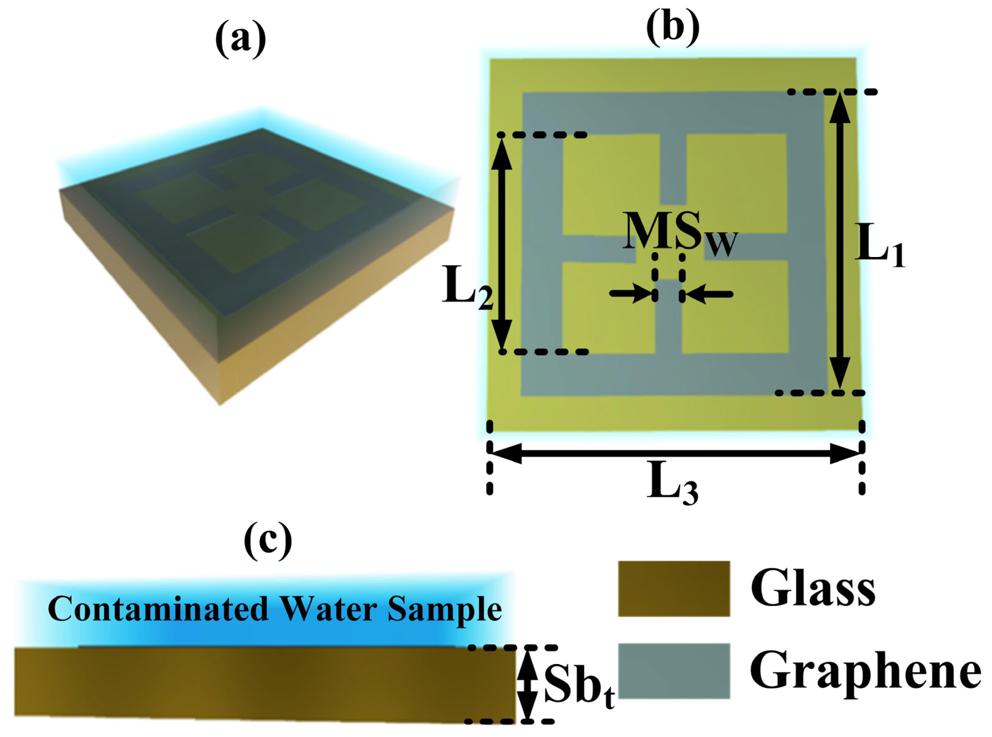
2. Design and Modeling

The graphene-metasurface-inspired optical sensor with glass material as a substrate is developed. The structural view, as well as the top view and the front view of the design, is presented in Figure 1a–c, respectively. The parameters for the given structure are as follows: length of the structure L1 is 8 μm, L2 is 7 μm, the height of graphene pattern is 0.34 nm, and width of the meta surface pattern MSW is 1 μm. The length of the whole structure L3 is 10 μm. substrate (glass material) thickness, Sbt, is 1.5 μm. The contaminated water samples are placed above the graphene metasurface, which is placed above the glass substrate, as presented in Figure 1c. The optical properties (i.e., RI, permittivity, permeability) of the substrate material affecting the transmission are used to calculate the optical characteristics of glass, which are taken from [17]. Other than this, the thickness of the substrate also affects the transmission [18]. The combination of glass and graphene initially appears complicated since it is difficult to generate graphene on a glass substrate using the conventional CVD method. However, a novel approach for the deposition of graphene on insulating surfaces has been presented in [19], which can produce graphene on glass without the use of a metal catalyst in about 5 min at a rate of 37 nm/min. Due to the extraordinary features of graphene, including its high conductivity and excellent tunability, it can easily detect water contamination.

2.1. Model of Graphene Conductivity

The conductivity of graphene can be defined with the help of the following Equations (1)–(4) [20]:
ε   ( ω ) = 1 + σ s ε 0 ω
σ i n t r a = j e 2 k B T π 2   ( ω j 2 Γ ) ( μ c k B T + 2   ln ( e μ c k B T + 1 ) )
σ i n e t r = j e 2 4 π   ln ( 2 | μ c | ( ω j 2 Γ ) 2 | μ c | + ( ω j 2 Γ ) )  
σ s = σ i n t r a + σ i n t e r
Here, all the represented symbols stand for their usual meanings, and more details on them are made available in the Supplementary Material.

2.2. Sensor’s Performance Deciding Parameters

Sensor’s performance evaluation parameters are derived and can be calculated as indicated in Equations (5)–(13) [21,22,23]:
S = Δ f Δ n
F O M = S F W H M
Q = f r F W H M
S N R = Δ f F W H M
D R = λ r F W H M
D A = 1 F W H M
D L = ( Δ n 1.5 ) ( F W H M Δ f ) 1.25
S R = S × D L
U C = 2 ( Δ f ) 0.75 ( F W H M ) 0.25 9
All the represented symbols stand for their usual meanings, and more details on them are made available in the Supplementary Material.

3. Results and Discussion

When simulating the designs shown in Figure 1 with COMSOL Multiphysics [24], planar light along the z-axis is employed to generate a frequency that ranges from 0.1 to 1 THz. Tetrahedral meshing is what is being performed here. The transmittance plots for several structural variations, such as glass material thickness, metasurface pattern width, and the electric field intensity (EFI) confirming the attained transmittance plots with heavy metals detection is included in Figure 2, Figure 3, Figure 4, Figure 5 and Figure 6.

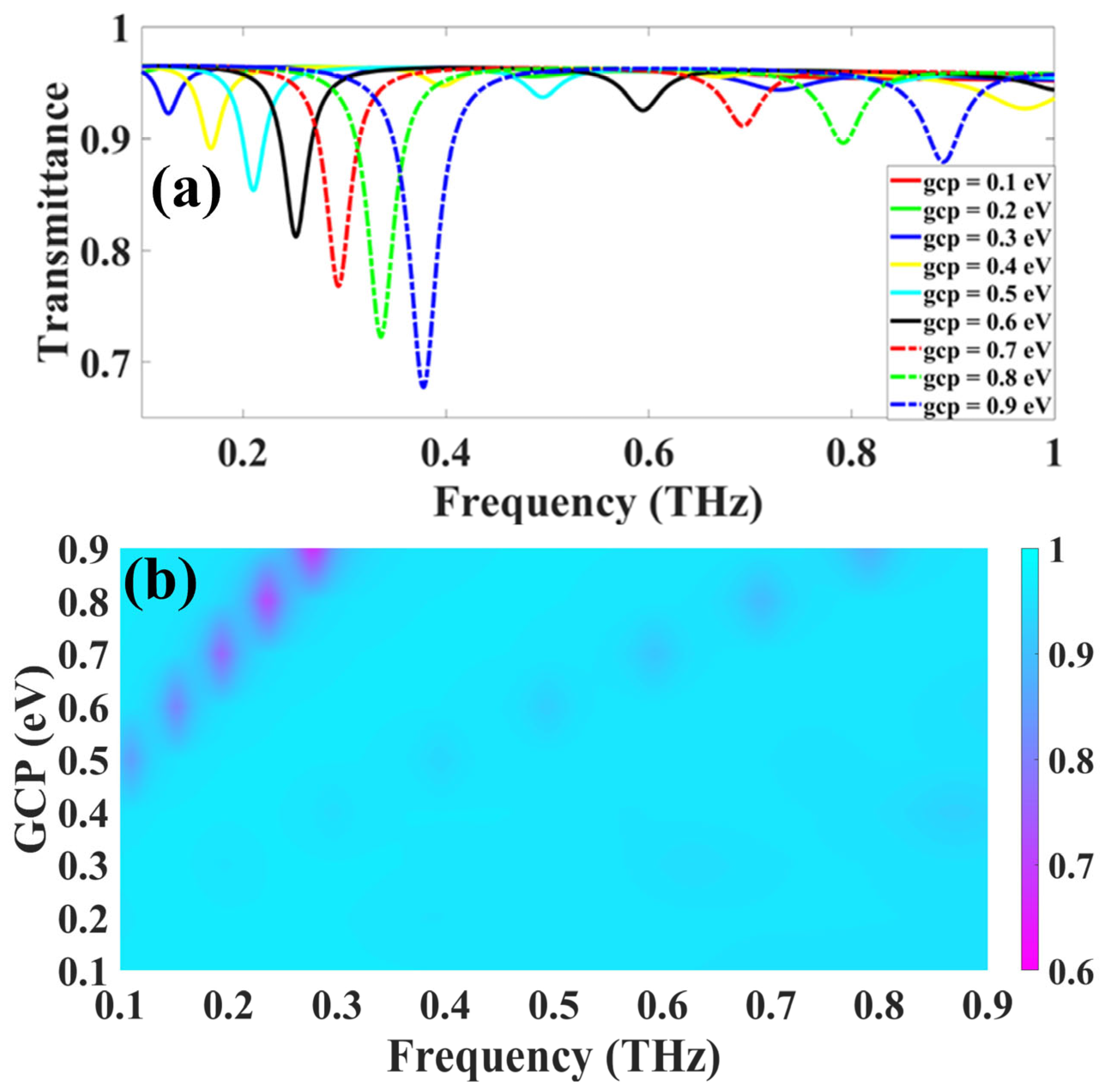
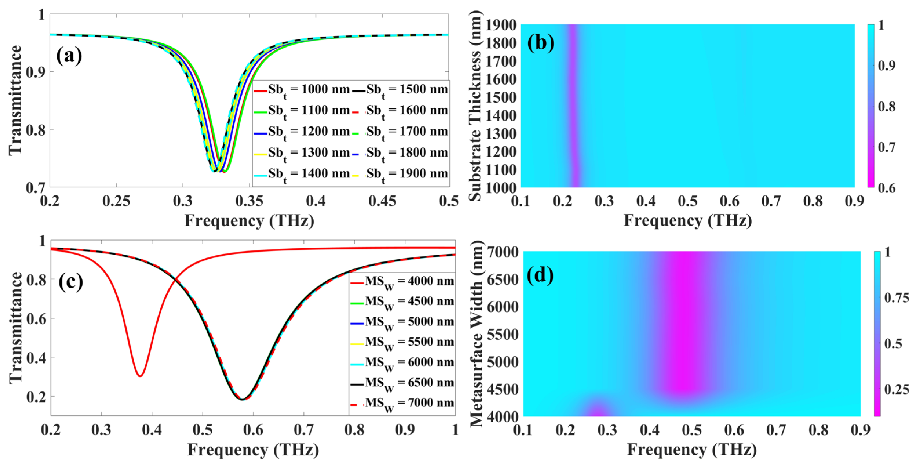
3.1. Structure Optimization

To start with, we checked the impact of Graphene Chemical Potential (GCP) on the transmittance response of the proposed sensor. To check the impact, GCP is changed from 0.1 eV to 0.9 eV with the uniform increment of 0.1 eV, and the attained response is exhibited in Figure 2 in the form of the line as well as color plots. The line plot in Figure 2a demonstrates the gradual increment in transmittance drop as the GCP enhances, and it is also noticed that for 0.1 eV and 0.2 eV, we do not attain any drop in transmittance in the considered range of frequency. It is possible that we would achieve the transmittance drops for 0.1 eV and 0.2 eV before or after the considered range of frequencies. In other words, for these two values, we achieve the perfect transmittance in the considered frequency range. Though as we increase the GCP from 0.3 eV to 0.9 eV, the transmittance drop gradually increases from 92.25% to 67.74%, as depicted in Figure 2a. In addition to that, it is also noticed that in the span of 0.4 THz to 1 THz, we observe another drop in transmittance for 0.3 eV to 0.9 eV, but the magnitude of this drop is comparatively very small compared to the first scenario. The reason behind achieving the increased transmittance drops as the GCP increases is that as we increase GCP, it increases the graphene conductivity, which as a result, provides the dipper transmittance response. Therefore, for the purpose of this study, we decided to select the 0.2 THz to 0.4 THz range for further investigation. Figure 2b demonstrates the color plot depicting the shift in the transmittance plot. It is observed that as we increase the GCP, the transmittance also moves toward the right side, and this phenomenon is confirmed for both ranges, i.e., from 0.2 THz to 0.4 THz and from 0.5 THz to 1 THz.
For further experimentation, we performed structural optimization to attain the optimal design, and to attain this, we varied the glass material thickness and the width of the metasurface pattern, and the corresponding results are presented in Figure 3. We varied the glass material thickness from 1000 nm to 1900 nm with a uniform rise of 100 nm, and its effect on transmittance is showcased in Figure 3a,b. Figure 3a,b depicts the impact of glass material thickness on transmittance drops. It is well noticed from Figure 3a that with the increasing glass material thickness, the magnitude of transmittance drop does not change. In other words, the uniform transmittance drop is acquired for every value of glass material thickness, Sbt. Therefore, for further explanation, we investigated the color plot that is exhibited in Figure 3b. The color plot clearly depicts that the transmittance response is identical, but a slight left-side movement is observed in the transmittance response. As we can observe, the transmittance response varies in 0.30 to 0.35 THz span. It is noticed that for 1000 nm, the transmittance drop of 72.61% is achieved at 0.331 THz, and for 1900 nm, the transmittance drop of magnitude 72.63% is attained at 0.323 THz. At last, we have varied the metasurface pattern width, MSW, from 4000 nm to 6500 nm with a uniform rise of 500 nm, and its impact on transmittance is exhibited in Figure 3c,d. Figure 3c reports the plot that showcases the impact of MSW on transmittance, and it is very clear from the figure that the uniform transmittance of 77.5% is obtained for the MSW values of 4500–6500 nm. The only different results are achieved for the MSW of 4000 nm, and the magnitude of transmittance attained at this point is 30.23% at 0.377 THz. At this value, the graphene metasurface’s shape changes and covers most parts of the substrate, and hence the abrupt change in transmittance is observed. As we increase the metasurface pattern width, the area covered by the graphene layer also decreases marginally, but as the GCP is fixed at 0.9 eV, we observe the almost identical and wide transmittance response for the rest of the values. While for further explanation, we provided the color plot that exhibits the one shift that is observed for 4000 nm of MSW value which is reported in Figure 3d. For the rest of the values, the magnitude of transmittance is 18.3%, and most of the responses overlap at 0.578 THz frequency; to avoid this and achieve a narrow response, we decided to keep the MSW value as 4000 nm. The optimal parameters set for the proposed graphene-metasurface-inspired sensor structure are as follows: glass material thickness, Sbt is 1500 nm, metasurface pattern width, MSW, is 4000 nm, GCP is 0.9 eV, and the rest of the parameters are as it is from Section 2.

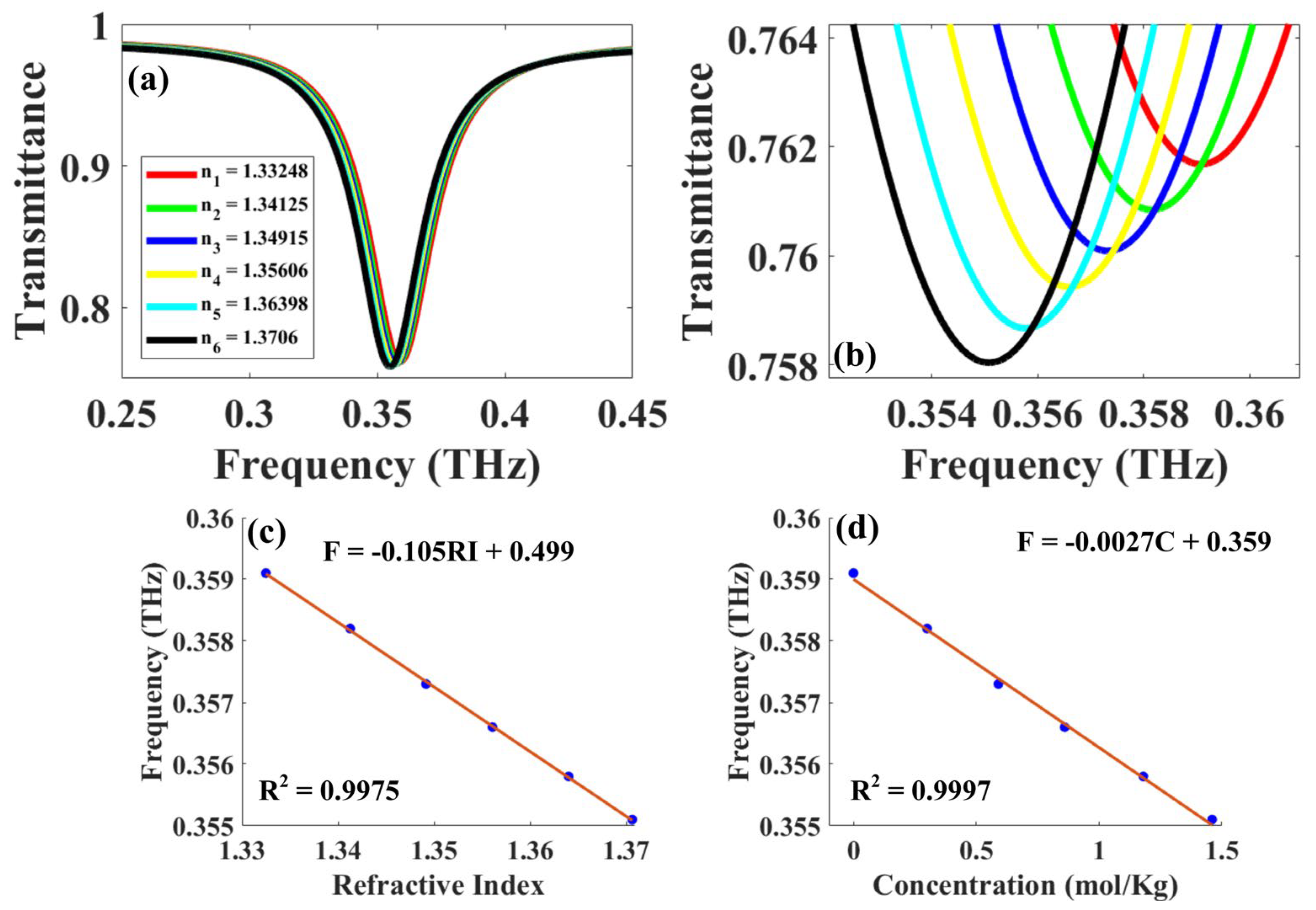
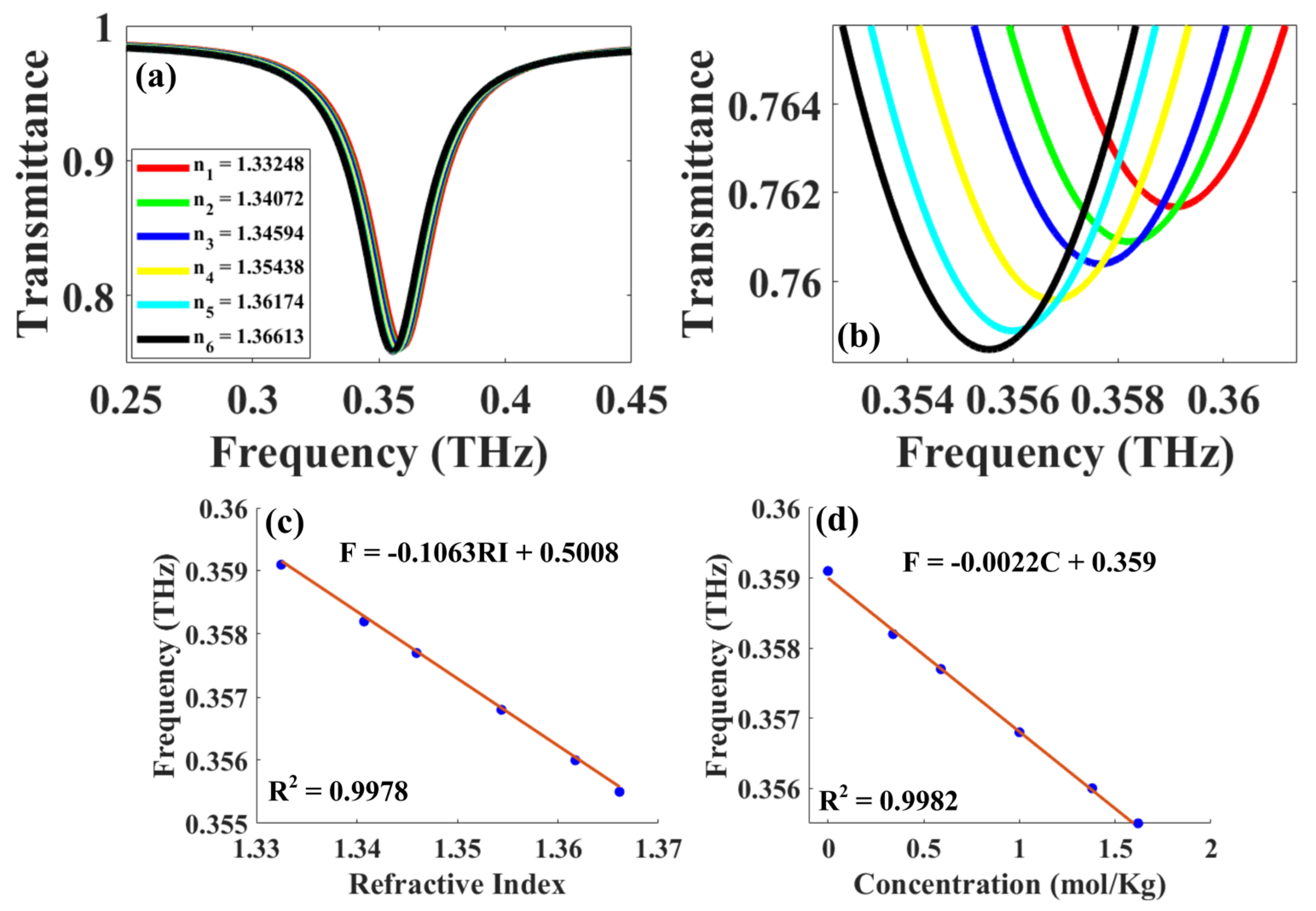
3.2. Detection of Heavy Metals for Efficient and Rapid Water Treatment

In particular, high dosages of Cu2+ and Mg2+ in drinking water could cause several risks to living organisms. These threats include abdominal pain, vomiting, headache, nausea, anemia, diarrhea in small children, damage to the liver, and damage to the kidneys [25]. As a result, the identification of these heavy metals could potentially be of some importance. In this scenario, the rise in the quantity of these metals causes an increase in the refractive index of the polluted water when it is measured at room temperature (25 °C) [26]. The linear relationship for both contaminants is as follows:
n w a t e r + C u 2 + = 1.3326 + 0.029237 M 0.0021765 M 2
n w a t e r + M g 2 + = 1.3328 + 0.023179 M 0.001588 M 2
From Equation (14), we calculated the refractive indices (RIs) of Cu2+ contaminated water for different concentrations of Cu2+. The RIs of 1.33248, 1.34125, 1.34915, 1.35606, 1.36398, and 1.3706 was calculated for uncontaminated water, with 0.3 mol/kg, 0.59 mol/kg, 0.86 mol/kg, 1.18 mol/kg, and 1.46 mol/kg concentration of Cu2+ contamination, respectively and the proposed graphene-metasurface-inspired sensor was simulated for this values, and the corresponding detection results and performance analysis is correspondingly presented in Figure 4 and Table 1. Figure 4a represents the impact of various concentrations and in terms of the particular RI for that concentration calculated from Equation (14) on transmittance. The result was carried out for the frequency span of 0.25–0.45 THz, and the enhanced view of achieved results for better visibility is also presented in Figure 4b.
From Figure 4b, we have observed that the transmittance response of 76.17%, 76.08%, 76.01%, 75.94%, 75.87%, and 75.80% is achieved at 0.3591 THz, 0.3582 THz, 0.3573 THz, 0.3566 THz, 0.3558 THz, and 0.3551 THz is achieved for the Cu2+ concentration of 0 mol/kg, 0.3 mol/kg, 0.59 mol/kg, 0.86 mol/kg, 1.18 mol/kg, and 1.46 mol/kg resulting in the RIs of 1.32348, 1.34125, 1.34915, 1.35606, 1.36398, and 1.3706, respectively. The plot clearly shows that as the concentration of Cu2+ in water increases, the transmittance drop also increases, and the left-side movement in transmittance is also noticed from 0.3591 THz to 0.3551 THz resulting in the tuning of 40 GHz. It is possible that this response of the dip shifting is brought on by a change in the optical path length brought on by the concentration of Cu2+ and the condition of a constant phase shift [27]. In addition to that, the complete analysis of the spectral location of the resonance transmittance drop for Cu2+ in terms of concentration (mol/kg) and RI is carried out, and the corresponding fitted formulas with the R2 score of 0.9975 and 0.9997 is achieved, and the linear fitting formulas are as follows:
f r = 0.105   R I + 0.499
f r = 0.0027   C + 0.359
The plot exhibiting the linear fitting of resonance frequency vs. RI and resonance frequency vs. concentration is demonstrated in Figure 4c,d, respectively, with the mentioning of the linear fitting equation and R2 score.
Here, we would like to point out that the first RI corresponding to 0 mol/kg refers to pure water, i.e., water without any heavy metal contamination. Later, the absolute sensitivity (S) is calculated by considering the pure water RI as a set point, and the relative sensitivity (SR) is calculated to validate that the proposed sensor can also easily detect and separate two various concentrations of Cu2+ in the water solution. The sensor’s performance in terms of absolute sensitivity, relative sensitivity for RI, and various concentrations of Cu2+ as well as FOM, Q factor, SNR, DL, DA, DR, SR, and UC is also carried out, and the detailed analysis is reported in Table 1. With the sensor that has been presented, the highest absolute and relative sensitivities that have been reached are 107.98 GHz/RIU and 113.92 GHz/RIU, respectively. Furthermore, the detailed analysis for sensitivity in terms of concentration is carried out, and the maximum absolute as well as relative sensitivity of 3.05 GHz kg/mol and 3.10 GHz kg/mol are achieved, respectively, while excellent results for FOM (3.15 RIU−1 to 3.55 RIU−1) were attained, which are significantly more desirable for use in experimental research. The Q factor is what determines how steeply the transmittance drops down at certain points. The highest and minimum values of 11.22 and 11.06 are reached, demonstrating that the Q factor is excellent across the board for all concentrations of Cu2+ and clean water. In a similar vein, the sensor that has been described possesses the highest resolution, as shown by the low FWHM values of 32 GHz. These low values suggest a high resolution for all transmittance dips in both contaminated and clean water. We are able to acquire a DL that falls somewhere between 0.45 and 1.00 RIU with the sensor that we have created. The fact that the DA remains constant at 0.031 GHz−1 gives the impression that the suggested sensor is able to easily discern between the extremely similar drops in transmittance that occur at intervals of 0.031 GHz−1. The signal-to-noise ratio is a very small percentage, and it ranges from 0.022 to 0.028, which indicates that the signal is quite strong in comparison to the noise.
We estimated the RIs of Mg2+ contaminated water using Equation (15), and we performed this for a range of different Mg2+ concentrations. The RIs of 1.33248, 1.34072, 1.34594, 1.35438, 1.36174, and 1.36613 have been calculated for uncontaminated water, and with 0.34 mol/kg, 0.59 mol/kg, 1 mol/kg, and 1.38 mol/kg concentration of Mg2+ contamination, respectively. Additionally, the proposed graphene-metasurface-inspired sensor has been simulated for these values, and the corresponding detection results and performance analysis are exhibited in Figure 5 and Table 2. The effect that different concentrations have on transmittance is shown in Figure 5a, along with the particular RI that should be used for that concentration based on the results of Equation (15). The result was carried out for the frequency range of 0.25–0.45 THz, and an improved perspective of the results that were accomplished in order to improve their visibility is also provided in Figure 5b. From Figure 5b, we were able to determine that the transmittance response of 76.17%, 76.09%, 76.04%, 75.96%, 75.89%, and 75.85% is achieved at 0.3591 THz, 0.3582 THz, 0.3577 THz, 0.3568 THz, 0.356 THz, and 0.3555 THz for the Mg2+ concentration of 0 mol/kg, 0.34 mol/kg, 0.59 mol, 1 mol/kg, 1.38 mol/kg, and 1.62 mol/kg resulting in the RIs of 1.33248, 1.34072, 1.34594, 1.35438, 1.36174, and 1.36613, respectively. The plot demonstrates very clearly that the transmittance decrease also increases as the concentration of Mg2+ in water increases. Additionally, the left-side movement in transmittance is observed, going from 0.3591 THz to 0.3555 THz, which ultimately results in the tuning of 36 GHz. It is possible that this response of the dip shifting is brought on by a change in the optical path length brought on by the concentration of Mg2+ and the condition of a constant phase shift [27].
In addition to that, the comprehensive analysis of the spectral location of the resonance transmittance drops for Mg2+ in terms of concentration (mol/kg) and RI was carried out, and the corresponding fitted formulas with the R2 score of 0.9978 and 0.9982 were achieved. The linear fitting formulas are as follows:
f r = 0.1063   R I + 0.5008
f r = 0.0022   C + 0.359
In Figure 5c and Figure 5d, respectively, the plot demonstrating the linear fitting of resonance frequency vs. RI and resonance frequency vs. concentration is shown, together with the mentioning of the linear fitting equation and the R2 score.
In this context, we would like to point out that the first RI, which corresponds to 0 mol/kg, relates to pure water, which may be understood to mean water that is free of any pollution from heavy metals. After that, the absolute sensitivity (S) is calculated by using the pure water RI as a set point, and the relative sensitivity (SR) is calculated to validate that the proposed sensor can also easily detect and separate two different concentrations of Mg2+ in the water solution. Both of these calculations are performed in order to validate that the proposed sensor can detect and separate the two different concentrations of Mg2+. In addition, the performance of the sensor was evaluated in terms of absolute sensitivity, relative sensitivity for RI, and various concentrations of Mg2+, FOM, Q factor, SNR, DL, DA, DR, SR, and UC, and the comprehensive analysis is presented in Table 2. With the sensor that has been presented, the highest absolute and relative sensitivities that may be reached are 109.22 GHz/RIU and 113.9 GHz/RIU, respectively. Furthermore, the detailed analysis for sensitivity in terms of concentration is carried out, and the maximum absolute as well as relative sensitivity of 2.65 GHz kg/mol is achieved for both cases. While excellent results for FOM (from 2.98 RIU−1 to 3.55 RIU−1) have been attained, which are significantly more desirable for use in experimental research. The Q factor is what determines how steeply the transmittance drops down at certain points. The highest and minimum values of 11.22 and 11.07 are reached, demonstrating that the Q factor is excellent across the board for all concentrations of Mg2+ and clean water. In a similar vein, the sensor that has been described possesses the highest resolution, as shown by the low FWHM values of 32 GHz. These low values suggest a high resolution for all transmittance dips in both contaminated and clear water. We are able to acquire a DL that falls somewhere between 0.72 and 0.95 RIU with the sensor that we have created. The fact that the DA remains constant at 0.031 GHz−1 gives the impression that the suggested sensor is able to easily discern between the extremely similar drops in transmittance that occur at intervals of 0.031 GHz−1. The signal-to-noise ratio is a very small percentage, and it ranges from 0.016 to 0.028, which indicates that the signal is quite strong in comparison to the noise. Consequently, a comprehensive analysis of the spectrum location of the transmittance drops as it relates to fluctuations in the amounts of Cu2+ and Mg2+ is also presented. In this case, the transmittance drops of Cu2+ and Mg2+ exhibit a reaction that is analogous to that which is caused by changes in concentration. Cu2+ is highly responding compared to Mg2+ due to the rapid increase in the RI. This is because the increase in the RI in the case of Cu2+ is caused by the presence of Cu2+. A response such as this would be of interest if it helps the proposed system achieve the advantage of selectivity between the various categories of heavy metals. At last, a comparison of the proposed graphene-metasurface-inspired sensor with the available sensors has been performed and is reported in Table 3 in terms of sensitivity, FOM, Q factor, and applications.

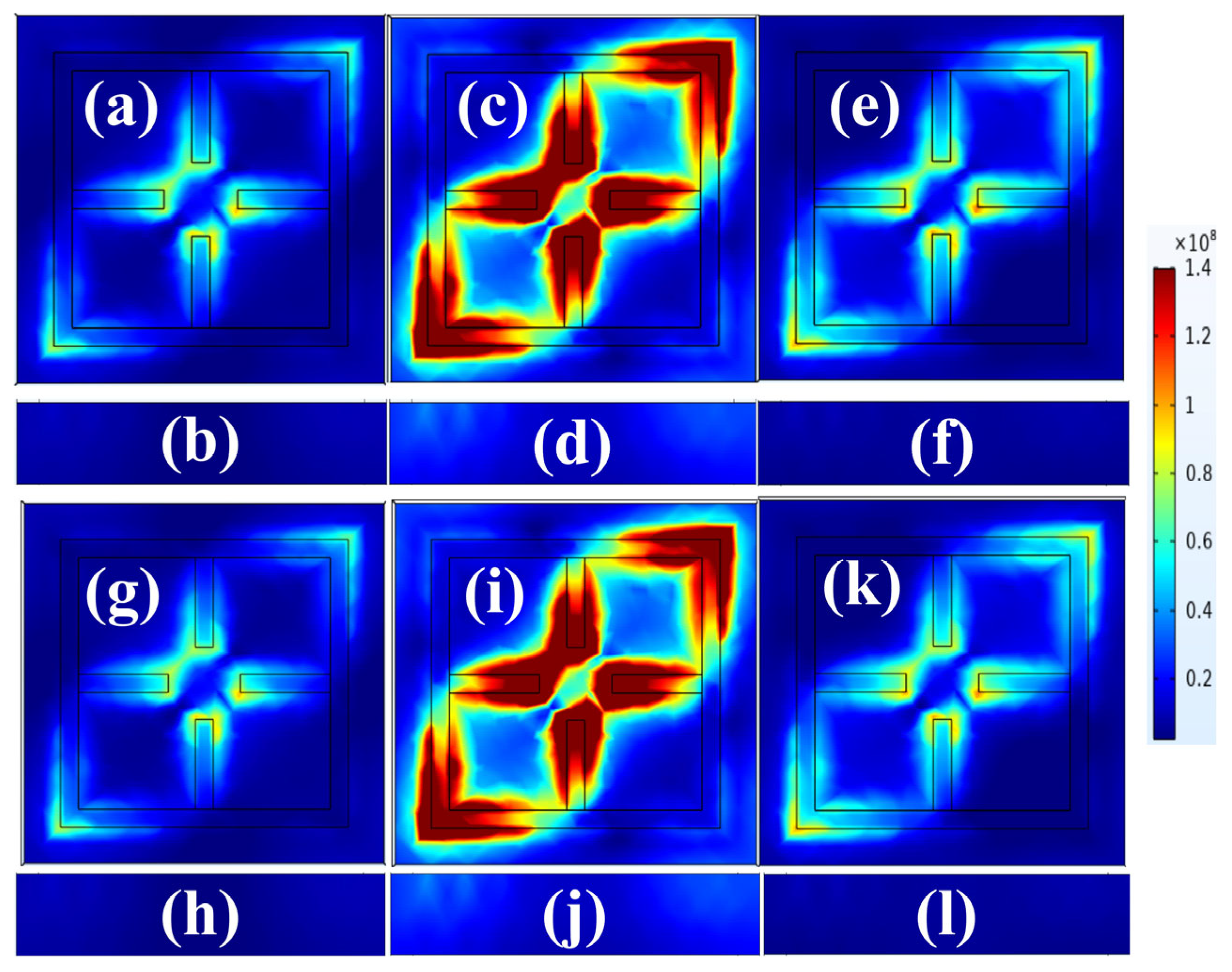
3.3. Electric Field Intensity Responses

Later, to validate the achieved transmittance response of the proposed graphene-metasurface-inspired sensor, an EFI response has been recorded, and the results are exhibited in Figure 6 for both Cu2+ and Mg2+ detection for various frequency values. Figure 6a–f represents the EFI plots for Cu2+ detection for 0.34 mol/kg concentration, and the EFI plot for 0.3 THz, 0.3582 THz, and 0.4 THz are presented for top and front views.
Figure 6a depicts the top view of the EFI plot for 0.3 THz, and it is observed that a very minor amount of electric field (EF) is concentrated on the edges of the inner pattern and the opposite side of the outer pattern while from the front view exhibited in Figure 6b clearly shows no amount of EF is present on the glass substrate. This response is in confirmation with the obtained near-perfect transmittance response at this particular frequency. While for 0.3582 THz, we are achieving the drop in transmittance at this particular point for Cu2+ concentration of 0.34 mol/kg, and the associated EFI plots are presented in Figure 6c,d. Figure 6c depicts the top view, which demonstrates the higher quantity of EF field concentration on the inner metasurface pattern as well as the opposite sides of the outer metasurface pattern, which agrees with the obtained drop in transmittance that depicts some amount of EF absorbed by the structure, and hence the EF field concentration is high at this particular frequency, and the front view also depicts the same as compared to the previous case some amount of EF is scattered on glass substrate. Now for 0.4 THz, we again achieve the near-perfect transmittance response, and from the EFI plots depicted in Figure 6e for the top view, we can observe a little bit higher scattering of EF on the inner metasurface pattern as well the opposite sides of the outer pattern compared to the first case and the scattering of EF on glass substrate is nearly zero from what we can observe from Figure 6f which also confirms the near perfect transmittance response.
The EFI graphs for the detection of Mg2+ at a concentration of 0.59 mol/kg are shown in Figure 6g–l, along with the EFI plots for 0.3 THz, 0.3577 THz, and 0.4 THz, which are provided for top and front views, respectively. The top view of the EFI plot for 0.3 THz is shown in Figure 6g, and it can be seen that only a very small amount of EF is concentrated on the edges of the inner pattern and the opposite side of the outer pattern. On the other hand, the front view shown in Figure 6h demonstrates very clearly that there is not even a trace of EF on the glass substrate at all. This response corroborates the findings that the acquired transmittance response at this specific frequency is really close to being perfect, while for 0.3577 THz, we are able to achieve the decline in transmittance at this particular point at a Mg2+ concentration of 0.59 mol/kg, and the associated EFI plots can be found in Figure 6i,j. Figure 6i depicts the top view, which demonstrates the higher quantity of EF field concentration on the inner metasurface pattern as well as the opposite sides of the outer metasurface pattern, which agrees with the obtained drop in transmittance that depicts some amount of EF absorbed by the structure and, as a result, the EF field concentration is high at this particular frequency, and the front view also depicts the same as compared to the previous case, some amount of EF is scattering as exhibited in Figure 6j. Now, for 0.4 THz, we once again achieve the near-perfect transmittance response, and from the EFI plots depicted in Figure 6k for the top view, we can observe a little bit higher scattering of EF on the inner metasurface pattern as well as the opposite sides of outer pattern compared to the first case, and the scattering of EF on glass substrate is nearly zero from what we can observe from Figure 6l, which also confirms the near perfect transmittance response

4. Conclusions

Heavy metal ion contamination of water supplies has significantly increased during the last century due to advances in industry and technology. Therefore, a lot of effort was put into developing chemical and physical methods for detecting and tracking the presence of these potentially harmful solutions. Therefore, in this study, we have presented a straightforward and effective sensing method based on the graphene metasurface for detecting several classes of heavy metal ions. The detection technique relied on the change in the location of the transmittance drops based on results owing to the variation in the amounts of Cu2+ and Mg2+ in water. In the meantime, our investigations have indicated that there has been a substantial variation in the spectral location of the transmittance drops. The design that has been suggested enables selection between various classes of heavy metal ions. In this case, the transmittance drops of Cu2+ and Mg2+ exhibit a reaction that is analogous to that which is caused by changes in concentration. The optimized structure is also obtained for the higher performance of the sensor. The proposed structure achieved the highest sensitivity of 113.92 GHz/RIU and 113.9 GHz/RIU, respectively, for Cu2+ and Mg2+. Furthermore, the lowest value of the FOM of 2.98 RIU−1 and the maximum Q factor of 11.22 are obtained. The proposed structure also exhibited a low detection limit as well as a resolution of 0.52 RIU and 78.14 THz, respectively. As a result of these findings, a simple and precise device for detecting contamination of water with heavy metals such as Cu2+ and Mg2+ with comparatively high performance is developed.

Supplementary Materials

The following supporting information can be downloaded at: https://www.mdpi.com/article/10.3390/photonics10010056/s1. Equations (S1)–(S4): A. Graphene Conductivity Analysis; Equations (S5)–(S13): B. Performance Defining parameters for the Developed Sensor. Refs. [20,21,22,23] are cited in Supplementary Materials.

Author Contributions

Conceptualization, A.H.M.A. and S.K.P.; Software, A.H.M.A. and J.S.; Data curation, A.H.M.A., J.S. and T.P.; Formal analysis, G.A.A., J.S., T.P. and A.A.; Funding acquisition, A.H.M.A.; Investigation, K.A. and T.P.; Methodology, A.H.M.A., J.S. and A.A.; Project administration, A.H.M.A. and S.K.P.; Supervision, A.H.M.A. and S.K.P.; Validation, A.A.; Writing—original draft, A.H.M.A., J.S., T.P., A.A. and S.K.P.; Writing—review and editing, A.H.M.A. and S.K.P. All authors have read and agreed to the published version of the manuscript.

Funding

The authors are thankful to the Deanship of Scientific Research at Najran University for funding this work under the Research Collaboration Funding program grant code (NU/NRP/SERC/11/2).

Institutional Review Board Statement

Not applicable.

Informed Consent Statement

Not applicable.

Data Availability Statement

The data will be made available at a reasonable request to the corresponding author.

Acknowledgments

The authors are thankful to the Deanship of Scientific Research at Najran University for funding this work under the Research Collaboration Funding program grant code (NU/NRP/SERC/11/2).

Conflicts of Interest

The authors declare no conflict of interest.

References

  1. de Souza, J.P.; Sposito, J.C.V.; do Amaral Crispim, B.; da Silva, F.G.; de Oliveira, K.M.P.; Kummrow, F.; do Nascimento, V.A.; Montagner, C.C.; Viana, L.F.; Solórzano, J.C.J.; et al. From Collection to Discharge: Physical, Chemical, and Biological Analyses for Fish Farm Water Quality Monitoring. Ecotoxicology 2019, 28, 13–25. [Google Scholar] [CrossRef] [PubMed]
  2. Zhang, Z.; Yang, M.; Yan, X.; Guo, X.; Li, J.; Yang, Y.; Wei, D.; Liu, L.; Xie, J.; Liu, Y.; et al. The Antibody-Free Recognition of Cancer Cells Using Plasmonic Biosensor Platforms with the Anisotropic Resonant Metasurfaces. ACS Appl. Mater. Interfaces 2020, 12, 11388–11396. [Google Scholar] [CrossRef] [PubMed]
  3. Taha, T.A.; Mehaney, A.; Elsayed, H.A. Detection of Heavy Metals Using One-Dimensional Gyroidal Photonic Crystals for Effective Water Treatment. Mater. Chem. Phys. 2022, 285, 126125. [Google Scholar] [CrossRef]
  4. Cesewski, E.; Johnson, B.N. Electrochemical Biosensors for Pathogen Detection. Biosens. Bioelectron. 2020, 159, 112214. [Google Scholar] [CrossRef]
  5. Rodriguez-Mozaz, S.; Marco, M.P.; Lopez De Alda, M.J.; Barceló, D. Biosensors for Environmental Applications: Future Development Trends. Pure Appl. Chem. 2004, 76, 723–752. [Google Scholar] [CrossRef] [Green Version]
  6. Leonard, P.; Hearty, S.; Brennan, J.; Dunne, L.; Quinn, J.; Chakraborty, T.; O’Kennedy, R. Advances in Biosensors for Detection of Pathogens in Food and Water. Enzyme Microb. Technol. 2003, 32, 3–13. [Google Scholar] [CrossRef]
  7. Wang, R.; Ren, Z.; Kong, D.; Hu, B.; He, Z. Highly Sensitive Label-Free Biosensor Based on Graphene-Oxide Functionalized Micro-Tapered Long Period Fiber Grating. Opt. Mater. 2020, 109, 110253. [Google Scholar] [CrossRef]
  8. Parmar, M.; Thakur, L.S. Heavy Metal Cu, Ni and Zn: Toxicity, Health Hazards and Their Removal Techniques by Low Cost Adsorbents. Int. J. Plant Sci. 2013, 3, 143–157. [Google Scholar]
  9. Izah, S.C.; Chakrabarty, N.; Srivastav, A.L. A Review on Heavy Metal Concentration in Potable Water Sources in Nigeria: Human Health Effects and Mitigating Measures. Expo. Health 2016, 8, 285–304. [Google Scholar] [CrossRef]
  10. Sharma, A.; Kumar, V.; Shahzad, B.; Tanveer, M.; Sidhu, G.P.S.; Handa, N.; Kohli, S.K.; Yadav, P.; Bali, A.S.; Parihar, R.D.; et al. Worldwide Pesticide Usage and Its Impacts on Ecosystem. SN Appl. Sci. 2019, 1, 1446. [Google Scholar] [CrossRef] [Green Version]
  11. Al-Saydeh, S.A.; El-Naas, M.H.; Zaidi, S.J. Copper Removal from Industrial Wastewater: A Comprehensive Review. J. Ind. Eng. Chem. 2017, 56, 35–44. [Google Scholar] [CrossRef]
  12. Vahed, H.; Nadri, C. Sensitivity Enhancement of SPR Optical Biosensor Based on Graphene–MoS2 Structure with Nanocomposite Layer. Opt. Mater. 2019, 88, 161–166. [Google Scholar] [CrossRef]
  13. Jadeja, R.; Charola, S.; Patel, S.K.; Parmar, J.; Ladumor, M.; Nguyen, T.K.; Dhasarathan, V. Numerical Investigation of Graphene-Based Efficient and Broadband Metasurface for Terahertz Solar Absorber. J. Mater. Sci. 2020, 55, 3462–3469. [Google Scholar] [CrossRef]
  14. Patel, S.K.; Parmar, J.; Katrodiya, D.; Nguyen, T.K.; Holdengreber, E.; Dhasarathan, V. Broadband Metamaterial-Based near-Infrared Absorber Using an Array of Uniformly Placed Gold Resonators. J. Opt. Soc. Am. B 2020, 37, 2163–2170. [Google Scholar] [CrossRef]
  15. Patel, S.K.; Surve, J.; Parmar, J.; Ahmed, K.; Bui, F.M.; Al-Zahrani, F.A. Recent Advances in Biosensors for Detection of COVID-19 and Other Viruses. IEEE Rev. Biomed. Eng. 2022, 16, 22–37. [Google Scholar] [CrossRef]
  16. Patel, S.K.; Surve, J.; Parmar, J. Detection of Cancer with Graphene Metasurface-Based Highly Efficient Sensors. Diam. Relat. Mater. 2022, 129, 109367. [Google Scholar] [CrossRef]
  17. Shioya, K.; Komatsu, T.; Kim, H.G.; Sato, R.; Matusita, K. Optical Properties of Transparent Glass-Ceramics in K2ONb2O5TeO2 Glasses. J. Non. Cryst. Solids 1995, 189, 16–24. [Google Scholar] [CrossRef]
  18. Yoon, J.; Cho, H.Y.; Shin, M.; Choi, H.K.; Lee, T.; Choi, J.W. Flexible Electrochemical Biosensors for Healthcare Monitoring. J. Mater. Chem. B 2020, 8, 7303–7318. [Google Scholar] [CrossRef]
  19. Xie, Y.; Cheng, T.; Liu, C.; Chen, K.; Cheng, Y.; Chen, Z.; Qiu, L.; Cui, G.; Yu, Y.; Cui, L.; et al. Ultrafast Catalyst-Free Graphene Growth on Glass Assisted by Local Fluorine Supply. ACS Nano 2019, 13, 10272–10278. [Google Scholar] [CrossRef]
  20. Patel, S.K.; Surve, J.; Parmar, J.; Natesan, A.; Katkar, V. Graphene-Based Metasurface Refractive Index Biosensor For Hemoglobin Detection: Machine Learning Assisted Optimization. IEEE Trans. Nanobioscience 2022. [Google Scholar] [CrossRef]
  21. Ahmed, A.M.; Shaban, M. Highly Sensitive Au–Fe2O3–Au and Fe2O3–Au–Fe2O3 Biosensors Utilizing Strong Surface Plasmon Resonance. Appl. Phys. B Lasers Opt. 2020, 126, 57. [Google Scholar] [CrossRef]
  22. Li, F.; He, K.; Tang, T.; Mao, Y.; Wang, R.; Li, C.; Shen, J. The Terahertz Metamaterials for Sensitive Biosensors in the Detection of Ethanol Solutions. Opt. Commun. 2020, 475, 126287. [Google Scholar] [CrossRef]
  23. Geng, Z.; Zhang, X.; Fan, Z.; Lv, X.; Chen, H. A Route to Terahertz Metamaterial Biosensor Integrated with Microfluidics for Liver Cancer Biomarker Testing in Early Stage. Sci. Rep. 2017, 7, 16378. [Google Scholar] [CrossRef] [PubMed] [Green Version]
  24. COMSOL Multiphysics® v. 6.0. Available online: www.comsol.com (accessed on 1 October 2022).
  25. Bent, S.; Böhm, K. Copper-Induced Liver Cirrhosis in a 13-Month Old Boy. Gesundheitswesen 1995, 57, 667–669. [Google Scholar]
  26. Urréjola, S.; Sánchez, A.; Hervello, M.F. Refractive Indices of Lithium, Magnesium, and Copper(II) Sulfates in Ethanol-Water Solutions. J. Chem. Eng. Data 2010, 55, 482–487. [Google Scholar] [CrossRef]
  27. Elsayed, H.A.; Sayed, F.A.; Aly, A.H. Graphene Deposited Liquid Crystal and Thermal Sensitivity Using Photonic Crystals. Phys. Scr. 2021, 96, 035503. [Google Scholar] [CrossRef]
  28. Patel, S.K.; Parmar, J.; Sorathiya, V.; Zakaria, R.; Dhasarathan, V.; Nguyen, T.K. Graphene-Based Plasmonic Absorber for Biosensing Applications Using Gold Split Ring Resonator Metasurfaces. J. Lightwave Technol. 2021, 39, 5617–5624. [Google Scholar] [CrossRef]
  29. Singh, R.; Cao, W.; Al-Naib, I.; Cong, L.; Withayachumnankul, W.; Zhang, W. Ultrasensitive Terahertz Sensing with High-Q Fano Resonances in Metasurfaces. Appl. Phys. Lett. 2014, 105, 171101. [Google Scholar] [CrossRef] [Green Version]
  30. Wei, Z.; Li, X.; Zhong, N.; Tan, X.; Zhang, X.; Liu, H.; Meng, H.; Liang, R. Analogue Electromagnetically Induced Transparency Based on Low-Loss Metamaterial and Its Application in Nanosensor and Slow-Light Device. Plasmonics 2017, 12, 641–647. [Google Scholar] [CrossRef]
  31. He, X.J.; Wang, L.; Wang, J.M.; Tian, X.H.; Jiang, J.X.; Geng, Z.X. Electromagnetically Induced Transparency in Planar Complementary Metamaterial for Refractive Index Sensing Applications. J. Phys. D Appl. Phys. 2013, 46, 365302. [Google Scholar] [CrossRef]
  32. Wan, M.; Yuan, S.; Dai, K.; Song, Y.; Zhou, F. Electromagnetically Induced Transparency in a Planar Complementary Metamaterial and Its Sensing Performance. Optik 2015, 126, 541–544. [Google Scholar] [CrossRef]
  33. Sahu, S.; Ali, J.; Yupapin, P.P.; Singh, G. Optical Biosensor Based on a Cladding Modulated Grating Waveguide. Optik 2018, 166, 103–109. [Google Scholar] [CrossRef]
  34. An, G.; Li, S.; Cheng, T.; Yan, X.; Zhang, X.; Zhou, X.; Yuan, Z. Ultra-Stable D-Shaped Optical Fiber Refractive Index Sensor with Graphene-Gold Deposited Platform. Plasmonics 2019, 14, 155–163. [Google Scholar] [CrossRef]
  35. Olyaee, S.; Najafgholinezhad, S.; Alipour Banaei, H. Four-Channel Label-Free Photonic Crystal Biosensor Using Nanocavity Resonators. Photonic Sens. 2013, 3, 231–236. [Google Scholar] [CrossRef]
Figure 1. Developed water contamination detection graphene-metasurface-inspired sensor (a) structural view (b) top view of meta surface design with length and width. (c) front view of meta surface design with width. The parameters for the given structure are as follows: length of the structure L1 is 8 μm, L2 is 7 μm, and the height of graphene pattern is 0.34 nm. Width of the meta surface pattern W is 1 μm. Length of the whole structure L3 is 10 μm. Thickness of the glass substrate material T1 is 1.5 μm.
Photonics 10 00056 g001
Figure 2. GCP affecting the transmittance plots, (a) line plot exhibiting the gradual drop in transmittance as the GCP enhances from 0.1 eV to 0.9 eV in a uniform rise of 0.1 eV, (b) color plot exhibiting the right shift in transmittance drops with the increment of GCP. Furthermore, it is noticed that the transmittance drop is not observable for 0.1 eV and 0.2 eV. While for rest of the GCPs, we attain two spectrums, one at around 0.3 THz and the other after 0.4 THz. Though the transmittance drop is not very significant for the second spectrum hence for the purpose of this study, we have considered the first spectrum of 0.3 THz. The highest transmittance drop is demonstrated at 0.9 eV at 0.378, and a drop of 67.33% is observed.
Photonics 10 00056 g002
Figure 3. Glass material thickness, Sbt affecting the transmittance plots (a) plot exhibiting the uniform and unchanged transmittance as the Sbt enhances from 1000 nm to 1900 nm in a uniform rise of 100 nm, (b) color plot exhibiting the left shift in transmittance drops with the increment of Sbt, Metasurface pattern width, MSW affecting the transmittance plots (c) plot exhibiting the uniform transmittance response for MSW values of 4000–7000 nm. The only different response is achieved for MSW of 4000 nm, and the comparatively low transmittance drop is observed as well at this point, (d) plot exhibiting the uniform transmittance response as the MSW enhances and the only change at 4000 nm is observed, which is clearly visible.
Photonics 10 00056 g003
Figure 4. Detection of Cu2+ contaminated water by employing developed graphene-metasurface-inspired sensor, (a) transmittance getting affected by increasing the concentration of Cu2+ in water from 0 mol/kg to 1.46 mol/kg, (b) transmittance response moving left and transmittance drop increment is observed as the Cu2+ contamination in water is increased, and as a result of the RI of water solution also increase from 1.32348 to 1.3706, (c) the curve fitting for RI vs. resonance frequency at which the transmittance drop is achieved for that particular RI, a linear fit with R2 score of 0.9975 is obtained, (d) the curve fitting for concentration vs. resonance frequency at which the transmittance drop is achieved for that particular concentration, a linear fit with R2 score of 0.9997 is obtained.
Photonics 10 00056 g004
Figure 5. Detection of Mg2+ contaminated water by employing developed graphene-metasurface-inspired sensor, (a) transmittance getting affected by increasing the concentration of Mg2+ in water from 0 mol/kg to 1.62 mol/kg, (b) transmittance response moving left and transmittance drop increment is observed as the Mg2+ contamination in water is increased, and as a result of the RI of water solution also increase from 1.32348 to 1.36613, (c) the curve fitting for RI vs. resonance frequency at which the transmittance drop is achieved for that particular RI, a linear fit with R2 score of 0.9978 is obtained, (d) the curve fitting for concentration vs. resonance frequency at which the transmittance drop is achieved for that particular concentration, a linear fit with R2 score of 0.9982 is obtained.
Photonics 10 00056 g005
Figure 6. EFI plots for the developed graphene-metasurface-inspired sensor structure at various frequencies for front top and front views, respectively, for Cu2+ detection (a,b) 0.3 THz, (c,d) 0.3582 THz, (e,f) 0.4 THz, for Mg2+ detection, (g,h) 0.3 THz, (i,j) 0.3577 THz, (k,l) 0.4 THz.
Photonics 10 00056 g006
Table 1. Graphene-metasurface-inspired sensor’s performance for Cu2+ Detection.
ParametersVarious Concentrations of Ethyl Butanoate Present in Dry Exhaled Breath
Concentration (C) (mol/kg)00.30.59 0.861.181.46
ΔC (mol/kg)0.30.290.270.320.28
N1.332481.341251.349151.356061.363981.3706
Δn0.008770.00790.006910.007920.00662
fr (THz)0.35910.35820.35730.35660.35580.3551
Δf (THz)0.00090.00090.00070.00080.0007
S (GHz/RIU)102.62107.98106.02104.76104.93
S (GHz kg/mol)3.003.052.912.802.74
SR (GHz/RIU)102.62113.92101.30101.01105.74
SR (GHz kg/mol)3.003.102.592.52.5
FWHM (GHz)3232.132.13232.132.1
FOM (RIU−1)3.203.553.163.153.29
Q Factor11.2211.1611.1311.1411.0811.06
SNR0.0280.0280.0220.0250.022
DR2.012.001.991.991.981.98
DA (THz−1)0.0310.0310.0310.0310.0310.031
DL (RIU)0.720.451.000.740.52
SR (GHz)78.4478.4483.2180.7983.53
UC (GHz)0.490.490.400.450.40
Table 2. Graphene-metasurface-inspired sensor’s performance for Mg2+ Detection.
ParametersVarious Concentrations of Ethyl Butanoate Present in Dry Exhaled Breath
Concentration (mol/kg)00.340.59 11.381.62
ΔC (mol/kg)0.340.250.410.380.24
N1.332481.340721.345941.354381.361741.36613
Δn0.008240.005220.008440.007360.00439
fr (THz)0.35910.35820.35770.356580.3560.3555
Δf (THz)0.00090.00050.00090.00080.0005
S (GHz/RIU)109.22104.01105.02105.98106.98
S (GHz kg/mol)2.652.372.32.252.22
SR (GHz/RIU)109.2295.78106.64108.7113.9
SR (GHz kg/mol)2.652.002.202.102.08
FWHM (GHz)3232.132.13232.132.1
FOM (RIU−1)3.402.983.333.393.55
Q Factor11.2211.1611.1411.1511.0911.07
SNR0.0280.0160.0280.0250.016
DR2.012.002.001.991.991.98
DA (GHz−1)0.0310.0310.0310.0310.0310.031
DL (RIU)0.720.950.730.740.80
SR (GHz)78.4490.8678.1480.7990.86
UC (GHz)0.490.310.490.450.31
Table 3. Proposed Sensor’s Performance comparison with the available literature.
Sensor DesignSensitivityFOM
(RIU−1)
Q FactorApplication
Proposed design113.92 GHz/RIU3.1511.22Cu2+ Detection
Proposed design113.9 GHz/RIU2.9811.22Mg2+ Detection
Ref [28]1421 nm/RIU--Hemoglobin Detection
Ref [29]33 GHz/RIU---
Ref [30]294 nm/RIU--Biosensor, Slow-light devices
Ref [31]929 nm/RIU--Sensing in chemical and biological diagnosis
Ref [32]700 nm/RIU--Sensing
Ref [33]322 nm/RIU--Biosensing
Ref [34]1139 nm/RIU--Sensing
Ref [35]65.7 nm/RIU--Biochemical Sensing
Disclaimer/Publisher’s Note: The statements, opinions and data contained in all publications are solely those of the individual author(s) and contributor(s) and not of MDPI and/or the editor(s). MDPI and/or the editor(s) disclaim responsibility for any injury to people or property resulting from any ideas, methods, instructions or products referred to in the content.

