Communication

Optimal Design of Segmented Planar Imaging System Based on Rotation and CLEAN Algorithm

1
Aerospace Information Research Institute, Chinese Academy of Sciences, Beijing 100094, China
2
School of Electronic Engineering, Beijing University of Posts and Telecommunications, Beijing 100876, China
3
Qilu Aerospace Information Research Institute, Jinan 250100, China
4
School of Science, China University of Geosciences, Beijing 100083, China
*
Author to whom correspondence should be addressed.
Photonics 2023, 10(1), 46; https://doi.org/10.3390/photonics10010046
Submission received: 23 November 2022 / Revised: 18 December 2022 / Accepted: 30 December 2022 / Published: 2 January 2023
(This article belongs to the Special Issue Advanced Photonics Sensors, Sources, Systems and Applications)

Abstract

:
We propose a parity-baseline segmented planar imaging method with more frequency components by changing different baseline selection to achieve better imaging in the rotational process. A theoretical model of the parity-baseline segmented planar imaging system with rotational operation is built to analyze the imaging effect. The simulation results show that the imaging quality of the parity-baseline segmented planar imaging system has an approximately 20% increase by rotation compared with the conventional system. In addition, the CLEAN algorithm in radio astronomy imaging is also applied to the parity-baseline segmented planar imaging system, and the image quality is further improved by 55%. Such a new imaging method holds great potential toward astronomical observation and detection.

1. Introduction

In terms of astronomical observation, the National Aeronautics and Space Administration (NASA), the European Space Agency (ESA), and other institutions have successively developed the Hubble Space Telescope (HST), the Compton Gamma Ray Observatory (CGRO), the Chandra X-ray Observatory (CXO), the Kepler space telescope, and the Herschel and other space telescopes, and the main mirror aperture shows a rapid growth trend with the improvement of angular resolution requirements [1,2,3,4,5]. However, as the aperture of the space telescope imaging system increases, the overall size, weight, and power consumption of the system (Size, Weight, and Power, SWaP) will also increase greatly. The Segmented Planar Imaging Detector for Electro-optical Reconnaissance (SPIDER) was proposed by the LM Advanced Technology Center and UC Davis, which provides a 10~100 SWaP reduction [6,7]. The SPIDER is composed of a densely packed interferometer array based on an extremely thin layer of lenslets and a photonic integrated circuit (PIC) [8,9]. Ryan et al. demonstrated the working principle of PICs [10], and Wesley et al. studied PIC platforms and devices by using multilayer nitride-on-silicon integrated photonic circuits [11]. In addition, numerical simulations of the segmented planar imaging system with different optimal schemes were also carried out [12,13,14,15]. However, in order to improve the imaging quality of the system, the design of the segmented planar imaging was becoming more and more complicated in the previous work, limiting its practical application. From a practical point of view, the structure of the improved segmented plane imaging system should be substantially the same as that of the original SPIDER to reduce the difficulty of the manufacturing process.
In this paper, a parity-baseline segmented planar imaging method with rotational operation is firstly proposed. The theoretical model of segmented planar integrated optical imaging systems is established, and the pairing method of intermediate radial lens arrays is improved. By changing different baseline selection, the u-v frequency suitable for the rotating system is obtained. The imaging results of the non-uniform multi-stage sampling lens array are analyzed from the aspects of u-v frequency distribution and image quality. Moreover, the imaging effect of the segmented planar integrated optical imaging system is firstly optimized by the MP-CLEAN algorithm in this paper. The research results provide a theoretical basis for improving the new segmented planar integrated optical imaging system.

2. Theoretical Model

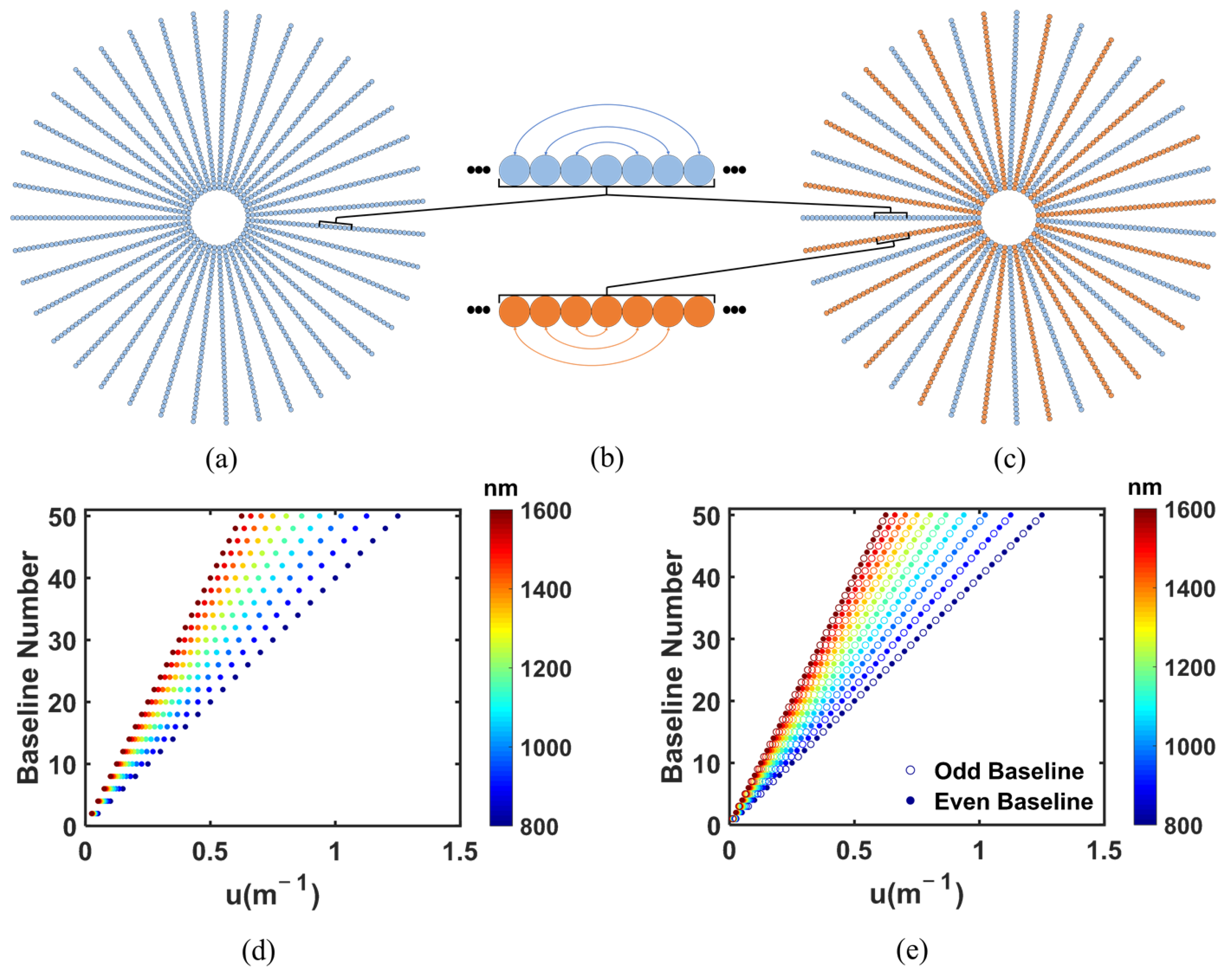
2.1. Parity Baseline Selection

The parity baseline selection is shown in Figure 1. Figure 1a shows the conventional SPIDER diagram with only one kind of baseline structure, which is used in the current state-of-the-art techniques and results. The corresponding baseline assignment for calculating u-v frequency is shown at the top of Figure 1b. Figure 1c shows the structure of the parity-baseline segmented planar imaging system composed of two kinds of PIC with different baseline selection, which is the fundamental structure we used in this paper. Except for that, it has the same structure as the conventional SPIDER. The blue baseline represents the even baseline assignment, and the orange baseline represents the odd baseline assignment, as shown in Figure 1b. The u-v frequency of the conventional SPIDER and the parity-baseline segmented planar imaging system can be obtained based on its baseline assignment, which is shown in Figure 1d,e. It can be clearly seen that the frequency components of the parity-baseline segmented planar imaging system are much higher than the conventional SPIDER, which shows that our method is much better.

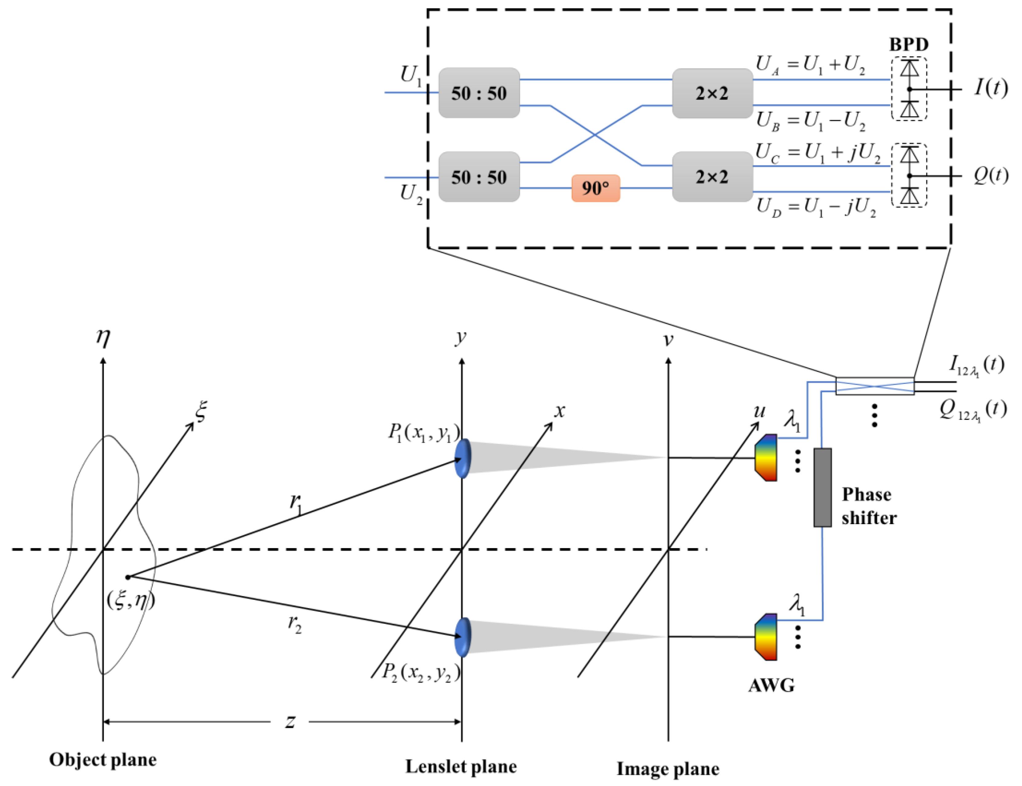
2.2. Signal Transmission Model

As shown in Figure 2, the light from the measured object reaches two lenslets P1 and P2 on the detection surface after passing through the z distance, and the cross-correlation strength J of P1 and P2 can be given by
J ( P 1 ; P 2 ) = U 1 ( t ) U 2 * ( t ) = I ( ξ , η ) e x p [ i 2 π λ ( r 2 r 1 ) ] χ ( θ 1 ) λ r 1 χ ( θ 2 ) λ r 2 d ξ d η
where U1(t) and U2(t) are the complex amplitude of light at P1 and P2, and I (ξ, η) is the light intensity of the measured object. χ(θ1) and χ(θ2) are the inclining factors of the two lights. The long distance between the measured object and the detector meets the condition of the near axis, so χ(θ1) = χ(θ2) ≈ 1, 1 r 1 r 2 1 z 2 and
r 1 = [ z 2 + ( x 1 ξ ) 2 + ( y 1 η ) 2 ] 1 / 2 z + ( x 1 ξ ) 2 + ( y 1 η ) 2 2 z
r 2 = [ z 2 + ( x 2 ξ ) 2 + ( y 2 η ) 2 ] 1 / 2 z + ( x 2 ξ ) 2 + ( y 2 η ) 2 2 z
We can bring the equations above into Equation (1) to get Equation (4)
μ ( u , v ) = I ( ξ , η ) e x p [ 2 π i ( ξ u + η v ) ] d ξ d η I ( ξ , η ) d ξ d η
where ( u , v ) = ( Δ x λ z , Δ y λ z ) , Δ x = x 2 x 1 , Δ y = y 2 y 1 , and μ ( u , v ) comprise the complex coherence factor which is proportional to the cross-correlation strength. Therefore, the light intensity of the measured object I ( ξ , η ) can be obtained by taking the complex degree of coherence as the inverse Fourier transform. However, because the u-v coverage is not continuous, the reconstructed image has some distortion. The solutions will be proposed to this problem. At the receiving end of the photodetector, I and Q can be written as
I = | U A | 2 | U B | 2 = 4 Re [ < U 1 ( t ) U 2 * ( t ) > ] = 4 Re [ J 12 ]
Q = | U C | 2 | U D | 2 = 4 Im [ < U 1 ( t ) U 2 * ( t ) > ] = 4 Im [ J 12 ]
In the case of ignoring the constant coefficient, I (ξ, η) can be given by
I ( ξ , η ) = F 1 { I 2 + Q 2 e x p [ arctan ( Q I ) ] }

2.3. Rotational Imaging

The simulation of an interference imaging system like SPIDER can take the imaging model as follows. Firstly, the optical transfer function (OTF) of the imaging system is obtained according to the lens arrangement and the baseline of the interference imaging system. Then, the pre-selected original image is transformed into the frequency domain and multiplied by OTF. Finally, the result of the product is transformed into a spatial domain, which is the result obtained by the whole system. The whole process can be described as
g ( x , y ) = F 1 { F [ f ( x , y ) ] × H ( u , v ) }
where g ( x , y ) is the imaging result, f ( x , y ) is the observation target, and H ( u , v ) represents the u-v distribution of the system after the specific lens arrangement and baseline selection.
The imaging results before and after rotation are assumed to be g 1 ( x , y ) and g 2 ( x , y ) . The u-v distributions of the lens before and after rotation are H 1 ( u , v ) and H 2 ( u , v ) , which are superimposed as follows
g 1 ( x , y ) + g 2 ( x , y ) = F 1 { F [ f ( x , y ) ] × H 1 ( u , v ) } + F 1 { F [ f ( x , y ) ] × H 2 ( u , v ) }   = F 1 { F [ f ( x , y ) ] × ( H 1 ( u , v ) + H 2 ( u , v ) ) }
where H 1 ( u , v ) + H 2 ( u , v ) means that their frequency graphs are superimposed on each other. This method also works for scenes with multiple rotations, and it can be given by
i = 1 n g i ( x , y ) = F 1 { F [ f ( x , y ) ] × i = 1 n H i ( u , v ) }
where n is the total number of spins, and i = 1 n H i ( u , v ) denotes the superposition of all u-v distributions. These distributions generally have more frequency coverage because the single imaging of the system has a frequency blank in the circumferential direction, which is an important factor in imaging. In addition, compared with the conventional SPIDER, the parity-baseline segmented planar imaging system can cover more frequency during the rotation due to the complementary relationship between the odd baseline and even baseline. Specifically, the odd baseline covers a completely different u-v frequency domain from the even baseline. In rotational imaging, the frequency blanks caused by the odd baseline can be partially covered by the even baseline and vice versa.

3. Results and Discussion

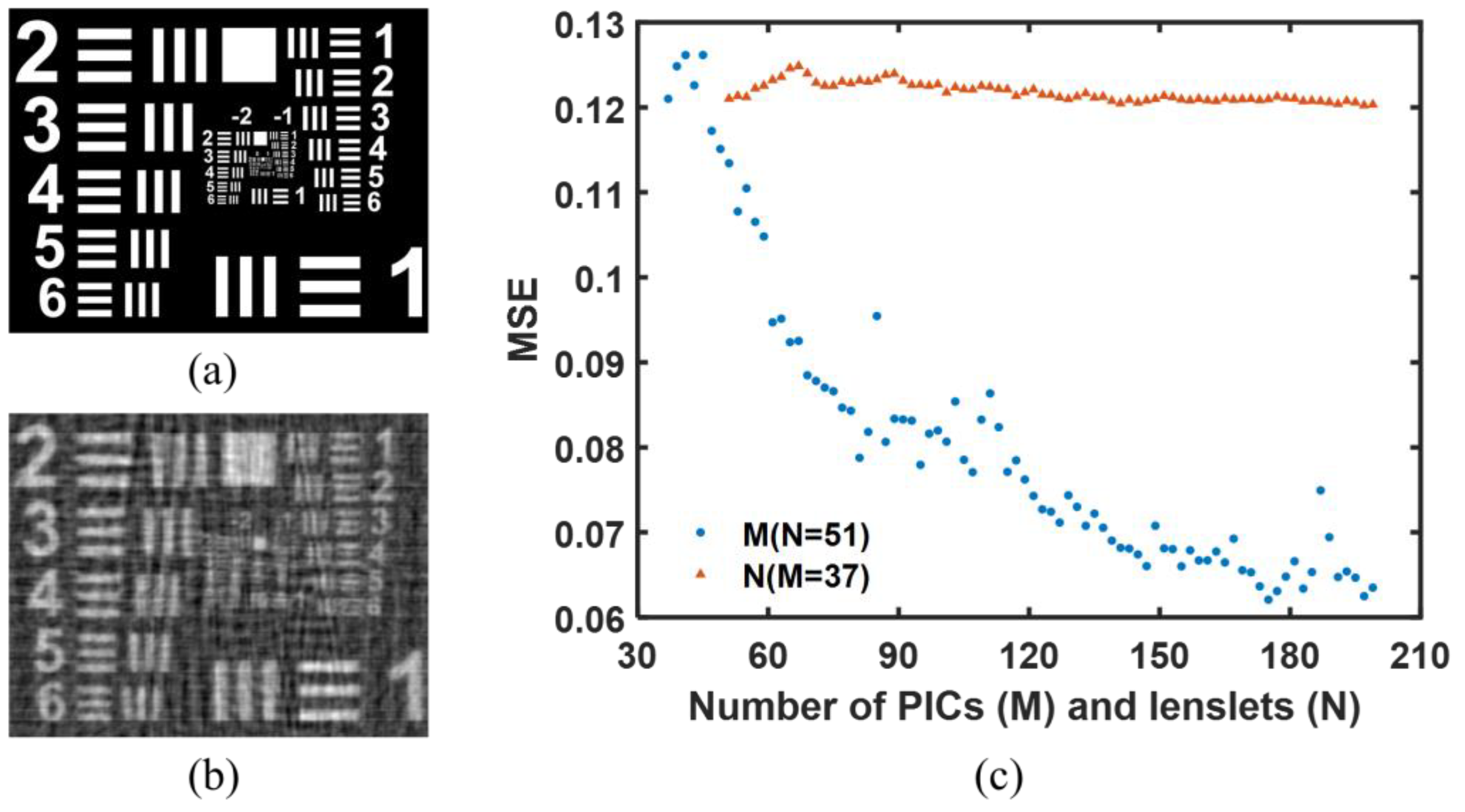
3.1. Parameter Effects

According to reference [12], the imaging system with an odd number of PICs has better imaging quality, so M is set to 37 for taking as examples. The other system parameters used for the simulations are listed in Table 1. From Figure 1b, it can be seen that there is an unused lenslet in the middle of the PIC with the even baseline assignment, so the number of lenslets per PIC should be odd. In the simulation, N is chosen to be 51, and the baseline selections of two lenslets in the even baseline assignment are (1, 51), (2, 50), (3, 49) … (25, 27). The corresponding baseline numbers are 50, 48, 46 … 2, respectively. The odd baseline selections are (1, 50), (2, 49), (3, 48) … (25, 26), and the baseline numbers are, respectively, 49, 47, 45 … 1. In order to keep the same structure for comparison, the system parameters in Table 1 apply to both the conventional SPIDER and the parity-baseline segmented planar imaging system.
The imaging result with different parameter effects is shown in Figure 3. The mean square error (MSE) is used as the evaluation index. Figure 3a,b shows the original image for the simulation and the imaging result with the parameters in Table 1. The corresponding MSE is 0.1210. To determine the effect of the number of PICs and lenslets on the imaging results, Figure 3c shows the relationship between the number of PICs and lenslets and the mean square error.
Figure 3c shows that with the increasing number of PICs and lenslets, the MSE of imaging results will decrease, which represents the higher quality of imaging and brings better improvement. However, the number of lenslets per PIC has little effect on MSE. In the u-v frequency domain, the increase in the number of PICs means the improvement of the circumferential frequency coverage, while the increase in the number of lenslets per PIC represents the improvement of the frequency coverage in radial direction. It can be clearly seen that raising frequency coverage along the circumference is more effective than frequency coverage in the radial direction.

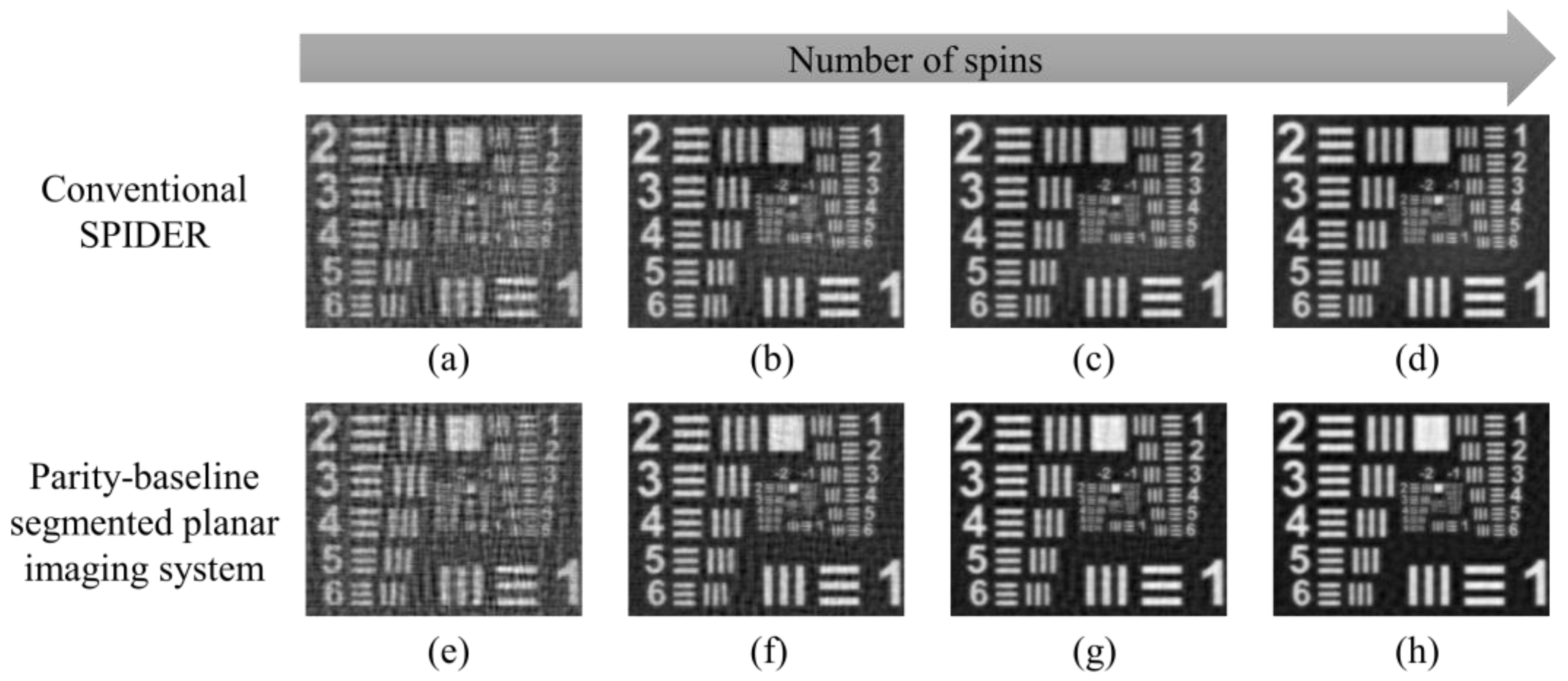
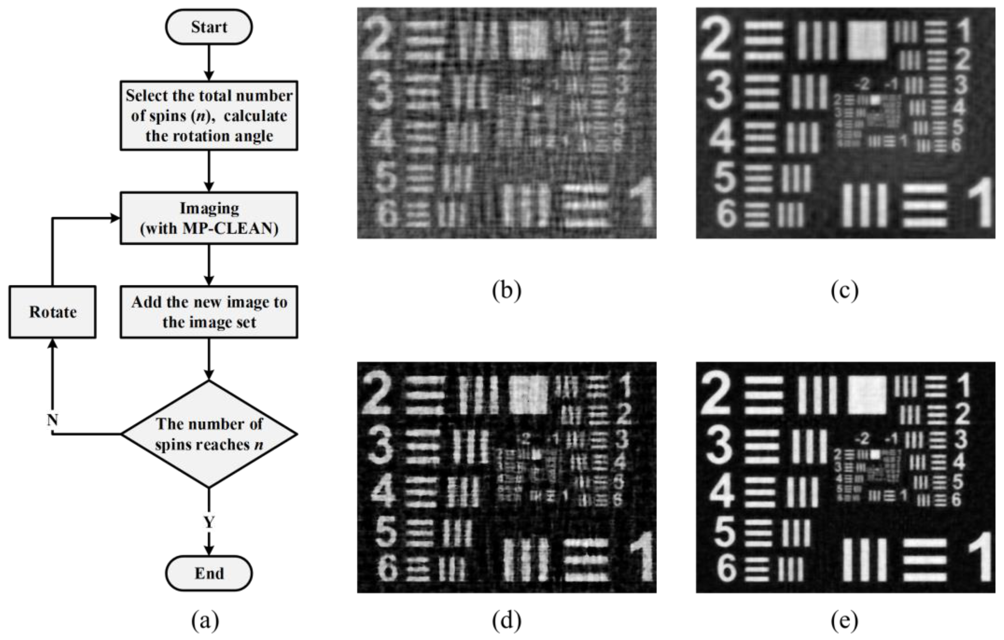
3.2. Rotational Imaging

Similarly, a rotational imaging system can effectively perform frequency coverage in the circumferential direction. Compared with the conventional SPIDER, the parity-baseline segmented planar imaging system is specially designed for rotational imaging. The rotation method is as follows. For both the conventional SPIDER and the parity-baseline segmented planar imaging system, when the angle between two adjacent PICs is α, the angle between two same baseline number of the parity-baseline segmented planar imaging system is 2α. This angle is divided into n equal parts. Every time the system is rotated with an angle of 2α/n corresponding to a number of spins of 1, the system gets an image. Then, these images are added together, and the final image is synthesized according to Equation (8). In the simulation, n is set to 15, and the imaging result of the two systems is shown in Figure 4.
Figure 4 shows the rotational imaging result of the conventional SPIDER and the parity-baseline segmented planar imaging system with the number of spins of 1, 5, 10, and 15. The MSEs of the conventional SPIDER are 0.1248, 0.08702, 0.07779, and 0.07229, while the MSEs of the parity-baseline segmented planar imaging system are 0.1172, 0.07562, 0.06163, and 0.05702. The imaging quality of the parity-baseline segmented planar imaging system is eventually improved by approximately 21%. It can be concluded that the conventional SPIDER and the parity-baseline segmented planar imaging system both have better imaging quality during rotational imaging. Because of the design of the parity-baseline segmented planar imaging system, its performance is better than that of the conventional SPIDER. Despite the limited improvement of single imaging quality, as the number of spins increases, the gap in imaging quality between the two systems becomes increasingly larger, which indicates that the parity-baseline segmented planar imaging system has greater application potential in rotational imaging.
Furthermore, it also can be seen that for both rotational imaging systems, the improvement of imaging quality does not have a linear relationship with the increase in the number of spins, which means the u-v frequency components have reached saturation, and if continued, the imaging quality would not get better but rather get worse. This is because that would cause frequency aliasing, which also affects the image in space distributions. Therefore, a future research direction would be investigating how to eliminate the frequency aliasing during rotational imaging to achieve the ultimate desired results.

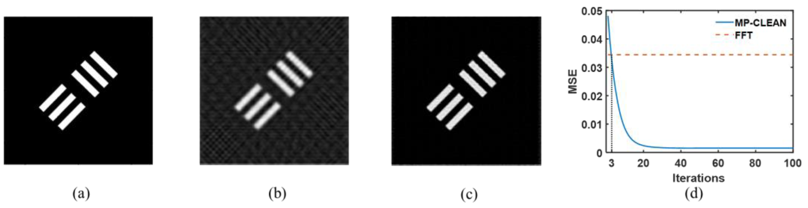
3.3. MP-CLEAN Algorithm

Radio astronomy aperture synthesis is often used for interference imaging in astronomy. In radio astronomy aperture synthesis observation, the CLEAN method is one of the most common ways for deconvolution. Clark [16] proposed a method for accelerating the CLEAN algorithm by performing on multiple points at the same time, called MP-CLEAN, which is also suitable for the segmented planar imaging system.
Figure 5 shows the imaging results before and after using the MP-CLEAN algorithm. The imaging result without the MP-CLEAN algorithm contains sidelobe noise, as shown in Figure 5b. By contrast, Figure 5c represents the imaging result after using the MP-CLEAN algorithm, and the sidelobe has been eliminated. The improvement of image quality can be achieved by the MP-CLEAN algorithm. MP-CLEAN is an iterative algorithm, and Figure 5d shows the running process of the MP-CLEAN algorithm, which illustrates the relationship between the MSE and the number of iterations. The red line represents the result of the Fast Fourier Transform (FFT), corresponding to the MSE without using the MP-CLEAN algorithm. It can be seen that the MP-CLEAN algorithm has exceeded the non-algorithm situation when the number of iterations reaches around three, and saturation presents after about twenty times. The MP-CLEAN algorithm not only has the ability to remove sidelobe noise in single imaging, but also removes more noise in superposition. Therefore, the MP-CLEAN algorithm can also be applied to rotational imaging to improve imaging quality.
The imaging process of the MP-CLEAN algorithm in a rotating segmented plane imaging system is shown in Figure 6a and can be described as follows. In a segmented planar imaging system, a single picture can be imaged, and the MP-CLEAN algorithm can improve the MSE. During rotational imaging, the u-v frequency domain of the system and the single imaging result are recorded and added up, which is the final imaging result. Figure 6b,c shows the imaging result of the conventional SPIDER without the MP-CLEAN algorithm, before and after rotation. The corresponding MSEs are 0.1248 and 0.07229, while the MSEs of the parity-baseline segmented planar imaging system with the MP-CLEAN algorithm before and after rotation are 0.05326 and 0.03208, respectively. The image quality is significantly improved, as shown in Figure 6d,e. It can be concluded that the MP-CLEAN algorithm applied to rotational imaging has more advantages than non-algorithm situations.
In practice, one can use the process of the segmented planar imaging system for rotation in Figure 6a to do rotational imaging. The result imaged by the segmented planar imaging system can be processed with the MP-CLEAN algorithm, which requires the system parameters. Then, the system or the observed object for experiment should be rotated by a specific angle and imaged. The new image with the MP-CLEAN algorithm should be added to the previous image set, and then the cycle should be continued. Due to the design for rotational imaging, the imaging quality of the parity-baseline segmented planar imaging system would be better than the conventional SPIDER.
To sum up, an optimal segmented planar imaging system structure for rotational imaging has been proposed as an alternative to the conventional SPIDER. The single imaging quality of the parity-baseline segmented planar imaging system is equivalent to the conventional SPIDER, but it has more advantages during rotational imaging. Because the structure of the parity-baseline segmented planar imaging system is almost unchanged compared with the conventional SPIDER, the method is also suitable for the new structure based on SPIDER and should be considered. The frequency aliasing during rotational imaging is a problem to be solved either by principle or subsequent algorithms. Furthermore, the MP-CLEAN algorithm is effective in this system. Both rotational imaging and the MP-CLEAN algorithm are methods of exchanging temporal resolution for spatial resolution, so the method proposed is more suitable for those insensitive to imaging time, such as remote sensing or astronomical imaging. The total rotation times and MP-CLEAN iteration times can also be reduced to improve time resolution.

4. Conclusions

We propose a parity-baseline method combined with rotation operation for segmented planar imaging, and the MP-CLEAN algorithm is applied to the system. A theoretical model of the parity-baseline segmented planar imaging system with rotational operation is established for analyzing imaging quality. Compared with the conventional SPIDER, the MSE of the parity-baseline segmented planar imaging system is improved by about 20% during rotation. The increase in image quality further increases by 55% using the MP-CLEAN algorithm. Such a parity-baseline rotating method with the MP-CLEAN algorithm has great potential in astronomical observation and detection.

Author Contributions

Z.M. wrote the manuscript; Y.L. revised and improved the manuscript; H.D. and X.Z. helped to conceive the idea; S.L., M.Z., L.G., Y.Z., J.Q. and J.W. were responsible for editing; Z.Z. supervised the manuscript. All authors have read and agreed to the published version of the manuscript.

Funding

This research was funded by the National Natural Science Foundation of China (Grant No. 62105341, Grant No.12074350) and the Natural Science Foundation of Shandong Province (Grant No. ZR2021QF126).

Institutional Review Board Statement

Not applicable.

Informed Consent Statement

Not applicable.

Data Availability Statement

Not applicable.

Conflicts of Interest

The authors declare no conflict of interest.

References

  1. Koekemoer, A.M.; Aussel, H.; Calzetti, D.; Capak, P.; Giavalisco, M.; Kneib, J.P.; Leauthaud, A.; Le Fèvre, O.; McCracken, H.J.; Massey, R.; et al. The cosmos survey: Hubble space telescope advanced camera for surveys observations and data processing. Astrophys. J. Suppl. Ser. 2007, 172, 196. [Google Scholar] [CrossRef] [Green Version]
  2. Gehrels, N.; Fichtel, C.E.; Fishman, G.J.; Kurfess, J.D.; Schönfelder, V. The Compton Gamma Ray Observatory. Sci. Am. 1993, 269, 68–77. [Google Scholar] [CrossRef]
  3. Weisskopf, M.C.; Tananbaum, H.D.; Van Speybroeck, L.P.; O’Dell, S.L. Chandra X-ray Observatory (CXO): Overview. In Proceedings of the Astronomical Telescopes and Instrumentation, Munich, Germany, 27 March–1 April 2000. [Google Scholar]
  4. Borucki, W.J. KEPLER Mission: Development and overview. Rep. Prog. Phys. 2016, 79, 036901. [Google Scholar] [CrossRef] [PubMed]
  5. Pilbratt, G.L.; Riedinger, J.R.; Passvogel, T.; Crone, G.; Doyle, D.; Gageur, U.; Heras, A.M.; Jewell, C.; Metcalfe, L.; Ott, S.; et al. Herschel Space Observatory-An ESA facility for far-infrared and submillimetre astronomy. Astron. Astrophys. 2010, 518, L1. [Google Scholar] [CrossRef] [Green Version]
  6. Yoo, S.J. Low-Mass Planar Photonic Imaging Sensor; No. HQ-E-DAA-TN56002; NASA: Washington, DC, USA, 2014.
  7. Duncan, A.; Kendrick, R.; Thurman, S.; Wuchenich, D.; Scott, R.P.; Yoo, S.J.B.; Su, T.; Yu, R.; Ogden, C.; Proiett, R. Spider: Next Generation Chip Scale Imaging Sensor. In Proceedings of the Advanced Maui Optical and Space Surveillance Technologies Conference, Maui, HI, USA, 15–18 September 2015. [Google Scholar]
  8. Kendrick, R.L.; Duncan, A.; Ogden, C.; Wilm, J.; Thurman, S.T. Segmented Planar Imaging Detector for EO Reconnaissance. In Proceedings of the Computational Optical Sensing and Imaging, Arlington, VA, USA, 23–27 June 2013. [Google Scholar]
  9. Badham, K.; Kendrick, R.L.; Wuchenich, D.; Ogden, C.; Chriqui, G.; Duncan, A.; Thurman, S.T.; Yoo, S.J.B.; Su, T.; Lai, W.; et al. Photonic Integrated Circuit-Based Imaging System for SPIDER. In Proceedings of the 2017 Conference on Lasers and Electro-Optics Pacific Rim (CLEO-PR). IEEE, Sands Expo and Convention Centre, Singapore, 31 July–4 August 2017; pp. 1–5. [Google Scholar]
  10. Scott, R.P.; Su, T.; Ogden, C.; Thurman, S.T.; Kendrick, R.L.; Duncan, A.; Yu, R.; Yoo, S.J.B. Demonstration of a Photonic Integrated Circuit for Multi-Baseline Interferometric Imaging. In Proceedings of the 2014 IEEE Photonics Conference, Hyatt Regency, La Jolla, San Diego, CA, USA, 12–16 October 2014. [Google Scholar]
  11. Sacher, W.D.; Huang, Y.; Lo, G.Q.; Poon, J.K.S. Multilayer silicon nitride-on-silicon integrated photonic platforms and devices. J. Light. Technol. 2015, 33, 901–910. [Google Scholar] [CrossRef]
  12. Guo-Mian, L.; Qi, L.; Yue-Ting, C.; Hua-Jun, F.; Zhi-Hai, X.; Jingjing, M. An improved scheme and numerical simulation of segmented planar imaging detector for electro-optical reconnaissance. Opt. Rev. 2019, 26, 664–675. [Google Scholar] [CrossRef]
  13. Chu, Q.; Shen, Y.; Yuan, M.; Gong, M. Numerical simulation and optimal design of segmented planar imaging detector for electro-optical reconnaissance. Opt. Commun. 2017, 405, 288–296. [Google Scholar] [CrossRef]
  14. Gao, W.P.; Wang, X.R.; Ma, L.; Yuan, Y.; Guo, D.F. Quantitative analysis of segmented planar imaging quality based on hierarchical multistage sampling lens array. Opt. Express 2019, 27, 7955–7967. [Google Scholar] [CrossRef] [PubMed]
  15. Gao, W.; Yuan, Y.; Wang, X.; Ma, L.; Zhao, Z.; Yuan, H. Quantitative analysis and optimization design of the segmented planar integrated optical imaging system based on an inhomogeneous multistage sampling lens array. Opt. Express 2021, 29, 11869–11884. [Google Scholar] [CrossRef]
  16. Clark, B.G. An efficient implementation of the algorithm ‘CLEAN’. Astron. Astrophys. 1980, 89, 377. [Google Scholar]
Figure 1. Differences in structure and frequency between traditional SPIDER and the parity-baseline segmented planar imaging system. (a) Structure of the conventional SPIDER; (b) Method of parity baseline selection; (c) Structure of the parity-baseline segmented planar imaging system; (d) The u-v frequency components of the conventional SPIDER; (e) The u-v frequency components of the parity-baseline segmented planar imaging system.
Photonics 10 00046 g001
Figure 2. Diagram of the light propagation in the segmented planar imaging system.
Photonics 10 00046 g002
Figure 3. Imaging result with different parameters. (a) Original image; (b) Imaging result with the parameters in Table 1; (c) The number of PICs and lenslets versus the mean square error (MSE).
Photonics 10 00046 g003
Figure 4. (ad) Rotational imaging result of the conventional SPIDER with the number of spins of 1, 5, 10, 15. (eh) Rotational imaging result of the parity-baseline segmented planar imaging system with the number of spins of 1, 5, 10, 15.
Photonics 10 00046 g004
Figure 5. (a) Original image for MP-CLEAN simulation. (b) Imaging result without MP-CLEAN. (c) Imaging result with MP-CLEAN. (d) Rendering of MP-CLEAN algorithm with iterations.
Photonics 10 00046 g005
Figure 6. (a) The imaging process of segmented planar imaging system based on rotation and MP-CLEAN. (b) Imaging result of the conventional SPIDER before rotation without MP-CLEAN. (c) Imaging result of the conventional SPIDER after rotation without MP-CLEAN. (d) Imaging result of the parity-baseline segmented planar imaging system before rotation with MP-CLEAN. (e) Imaging result of the parity-baseline segmented planar imaging system after rotation with MP-CLEAN.
Photonics 10 00046 g006
Table 1. System parameters used for simulations.
ParameterSymbolValue
Number of PICsM37
Number of lenslets per PICN51
Lenslet diameterd2 mm
Length of the longest baselineBmax100 mm
Wavelengthλ800~1600 nm
Channel numberq10
Object distancez100 km
Disclaimer/Publisher’s Note: The statements, opinions and data contained in all publications are solely those of the individual author(s) and contributor(s) and not of MDPI and/or the editor(s). MDPI and/or the editor(s) disclaim responsibility for any injury to people or property resulting from any ideas, methods, instructions or products referred to in the content.

