Nondestructive Thickness Measurement of Thermal Barrier Coatings for Turbine Blades by Terahertz Time Domain Spectroscopy

 , , , ,
Abstract
:1. Introduction
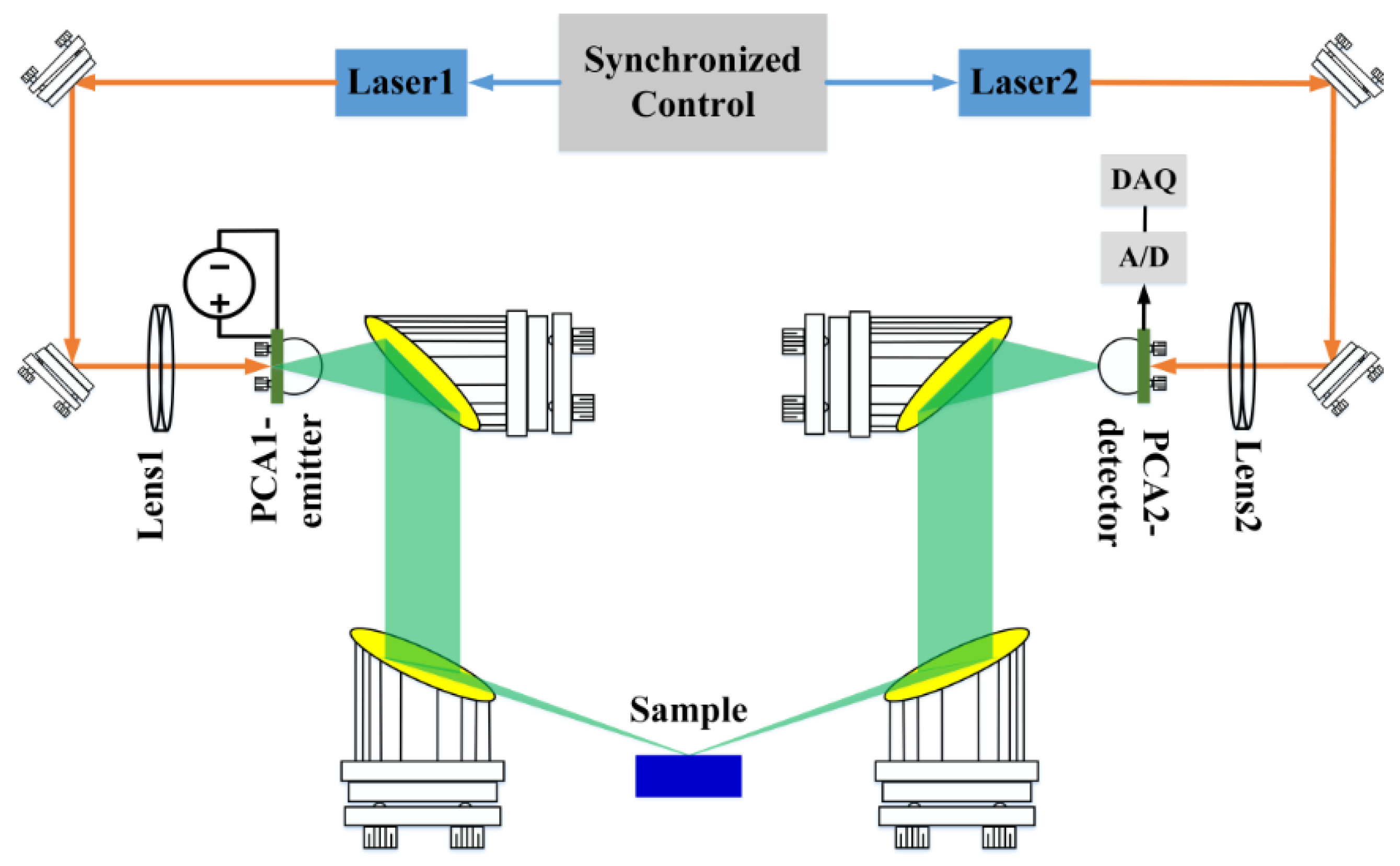
2. Materials and Methods
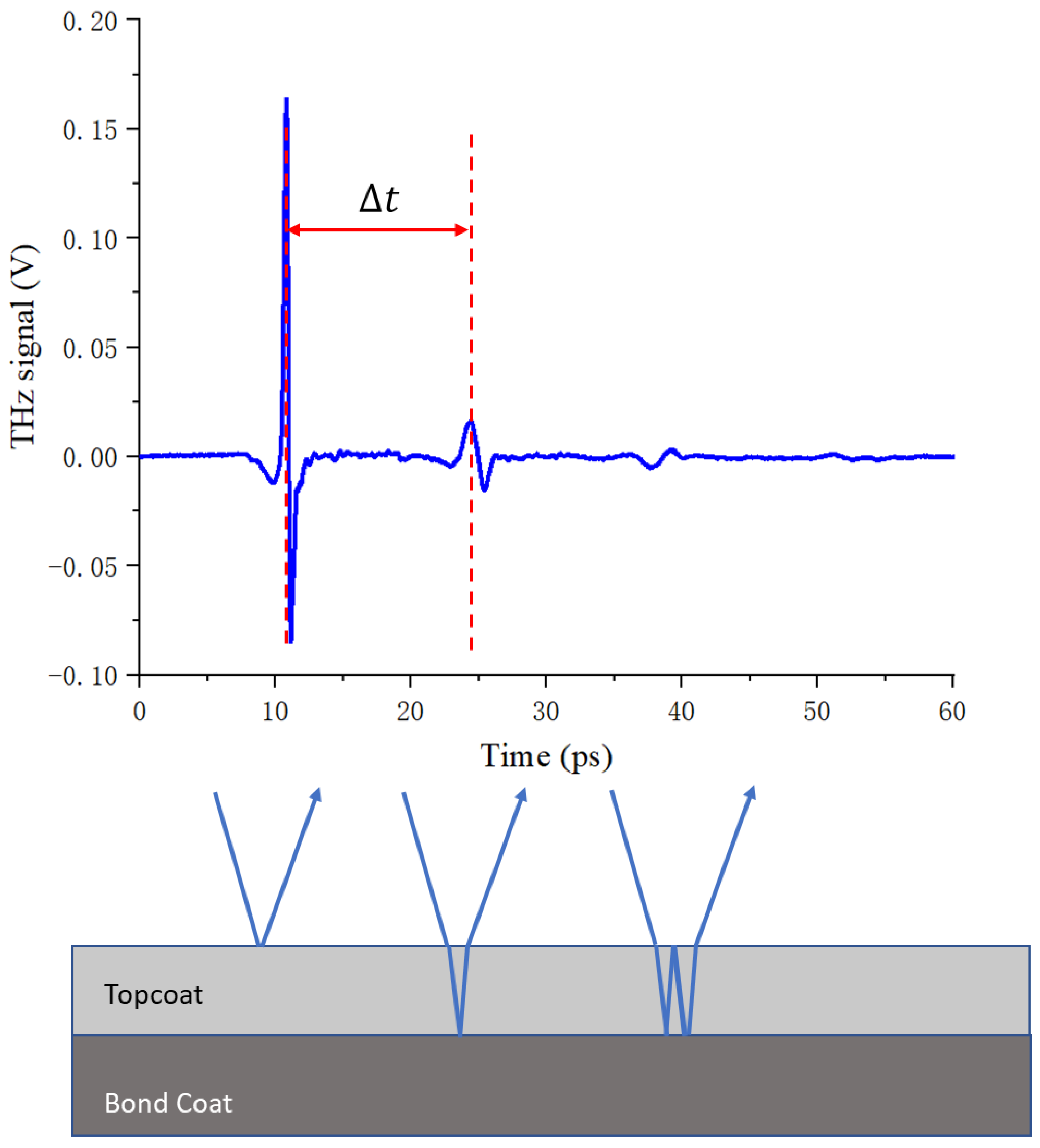
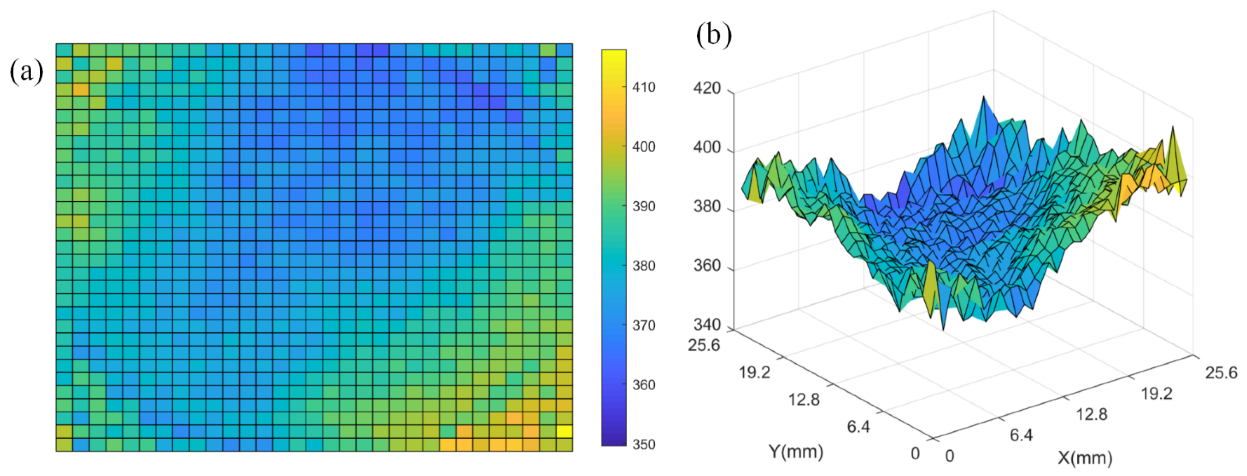
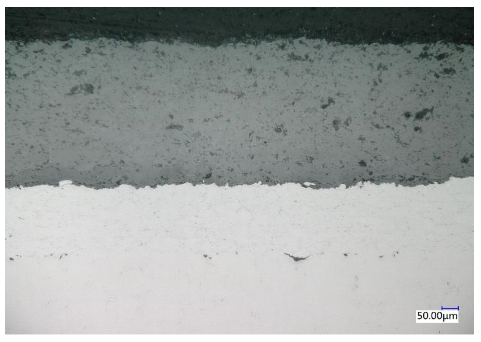
3. Results
4. Conclusions
Author Contributions
Funding
Institutional Review Board Statement
Informed Consent Statement
Data Availability Statement
Conflicts of Interest
References
- Reihani, E.; Motalleb, M.; Ghorbani, R.; Saoud, L.S. Load peak shaving and power smoothing of a distribution grid with high renewable energy penetration. Renew. Energy 2016, 86, 1372–1379. [Google Scholar] [CrossRef] [Green Version]
- Yuan, K.; Yu, Y.; Wen, J.-F. A study on the thermal cyclic behavior of thermal barrier coatings with different MCrAlY roughness. J. Vac. 2017, 137, 72–80. [Google Scholar] [CrossRef]
- Yan, K.; Xiang, Y.; Yu, H.Y.; Li, Z.R.; Wu, Y.; Sun, J. Effect of irregular microcracks on the hot corrosion behavior and thermal shock resistance of YSZ thermal barrier coatings. Surf. Coat. Technol. 2022, 431, 128038. [Google Scholar] [CrossRef]
- Ye, D.; Wang, W.; Zhou, H.; Fang, H.; Huang, J.; Li, Y.; Gong, H.; Li, Z. Characterization of thermal barrier coatings microstructural features using terahertz spectroscopy. Surf. Coat. Technol. 2020, 394, 125836. [Google Scholar] [CrossRef]
- Chen, D.; Dambra, C.; Dorfman, M. Process and properties of dense and porous vertically cracked yttria stabilized zirconia thermal barrier coatings. J. Surf. Coat. Technol. 2020, 404, 126467. [Google Scholar] [CrossRef]
- Chen, L.; Liao, D.; Guo, X.; Zhao, J.Y.; Zhu, Y.; Zhuang, S. Terahertz time-domain spectroscopy and micro-cavity components for probing samples: A review. Front. Inform. Technol. Electron. Eng. 2019, 20, 591–607. [Google Scholar] [CrossRef]
- Zhang, C.; Xue, T.; Zhang, J.; Liu, L.; Xie, J.; Wang, G.; Yao, J.; Zhu, W.; Ye, X. Terahertz toroidal metasurface biosensor for sensitive distinction of lung cancer cells. Nanophotonics 2021, 11, 101–109. [Google Scholar] [CrossRef]
- Zhang, J.; Mu, N.; Liu, L.; Xie, J.; Feng, H.; Yao, J.; Chen, T.; Zhu, W. Highly sensitive detection of malignant glioma cells using metamaterial-inspired THz biosensor based on electromagnetically induced transparency. Biosens. Bioelectron. 2021, 185, 113241. [Google Scholar] [CrossRef]
- Sun, L.; Xu, L.; Wang, J.; Jiao, Y.; Ma, Z.; Ma, Z.; Chang, C.; Yao, X.; Wang, R. A pixelated frequency-agile metasurface for broadband terahertz molecular fingerprint sensing. Nanoscale 2022, 14, 9681–9685. [Google Scholar] [CrossRef]
- Xu, W.; Huang, Y.; Zhou, R.; Wang, Q.; Yin, J.; Kono, J.; Ying, Y. Metamaterial-Free Flexible Graphene-Enabled Terahertz Sensors for Pesticide Detection at Bio-Interface. ACS Appl. Mater. Interfaces 2020, 12, 44281–44287. [Google Scholar] [CrossRef]
- Liu, L.H.; He, G.Q.; Wu, L.; Zheng, C.L.; Wang, S.L.; Zhang, Y.T.; Liang, L.J.; Xie, J.H.; Yao, J.Q. Non-Destructive detection of tobacco filter capsule by terahertz time domain spectroscopy. In Proceedings of the 2021 46th International Conference on Infrared, Millimeter and Terahertz Waves (IRMMW-THz), Chengdu, China, 29 August–3 September 2021; pp. 1–2. [Google Scholar]
- Dong, J.; Ribeiro, A.; Vacheret, A.; Locquet, A.; Citrin, D.S. Revealing inscriptions obscured by time on an early-modern lead funerary cross using terahertz multispectral imaging. Sci. Rep. 2022, 12, 3429. [Google Scholar] [CrossRef] [PubMed]
- Liu, L.H.; Jiang, H.T.; Wang, Y.; Shou, Q.H.; Xie, J.H.; Lu, Y.Q. Finger print sensor molding thickness none destructive measurement with Terahertz technology. In Proceedings of the 2017 China Semiconductor Technology International Conference (CSTIC), Shanghai, China, 12–13 March 2017; pp. 1–3. [Google Scholar]
- Su, K.; Shen, Y.; Zeitler, J.A. Terahertz Sensor for Non-Contact Thickness and Quality Measurement of Automobile Paints of Varying Complexity. IEEE Trans. Terahertz Sci. Technol. 2014, 4, 432–439. [Google Scholar] [CrossRef]
- Boissonnet, G.; Grosseau-Poussard, J.-L.; Bonnet, G.; Pedraza, F. Development of Thermal Barrier Coating Systems from Al Microparticles—Part II: Characterisation of Mechanical and Thermal Transport Properties. Coatings 2022, 12, 106. [Google Scholar] [CrossRef]
- Yong, L.; Chen, Z.; Mao, Y.; Yong, Q. Quantitative evaluation of thermal barrier coating based on eddy current technique. NDT E Int. 2012, 50, 29–35. [Google Scholar] [CrossRef]
- Fukuchi, T.; Fuse, N.; Okada, M.; Fujii, T.; Mizuno, M.; Fukunaga, K. Measurement of refractive index and thickness of topcoat of thermal barrier coating by reflection measurement of terahertz waves. Electron. Commun. Jpn. 2013, 96, 37–45. [Google Scholar] [CrossRef]
- Fukuchi, T.; Fuse, N.; Okada, M.; Ozeki, T.; Fujii, T.; Mizuno, M.; Fukunaga, K. Topcoat Thickness Measurement of Thermal Barrier Coating of Gas Turbine Blade Using Terahertz Wave. Electr. Eng. Jpn. 2014, 189, 1–8. [Google Scholar] [CrossRef]
- Burger, R.; Frisch, J.; Hübner, M.; Goldammer, M.; Peters, O.; Rönneberg, E.; Wu, D. THz-TDS Reflection Measurement of Coating Thicknesses at Non-Perpendicular Incidence: Experiment and Simulation. Sensors 2021, 21, 3473. [Google Scholar] [CrossRef] [PubMed]


| Measured Position | Thickness by THz-TDS (d1)/µm | Thickness by Metallographic Microscope (d2)/µm | Deviation (d1–d2)/µm | Deviation (d1–d2)/d2 |
|---|---|---|---|---|
| Position 1 | 378.8 | 386 | −7.2 | −1.86% |
| Position 2 | 372.4 | 370 | 2.4 | 0.65% |
| Position 3 | 362.1 | 350 | 12.1 | 3.45% |
| Position 4 | 352.6 | 350 | 2.6 | 0.74% |
| Position 5 | 346.6 | 340 | 6.6 | 1.94% |
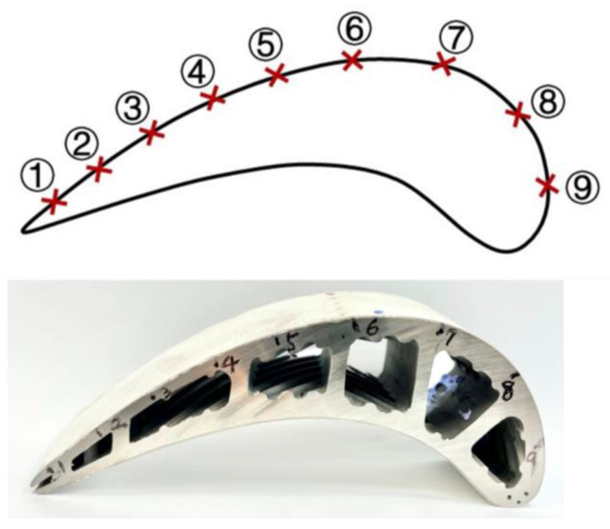
| Measured Position | Thickness by THz-TDS (d1)/µm | Thickness by Eddy Current Test (d2)/µm | Deviation (d1–d2)/µm | Deviation (d1–d2)/d2 |
|---|---|---|---|---|
| Position 1 | 361.55 | 366 | 4.45 | 1.22% |
| Position 2 | 374.51 | 370 | −4.51 | −1.22% |
| Position 3 | 375.47 | 377 | 1.53 | 0.41% |
| Position 4 | 374.62 | 380 | 5.38 | 1.42% |
| Position 5 | 333.83 | 330 | −3.83 | −1.16% |
| Position 6 | 375.74 | 340 | −35.74 | --- |
| Position 7 | 430.66 | 430 | −0.66 | −0.15% |
| Position 8 | 352.47 | 350 | −2.47 | −0.71% |
| Position 9 | 351.52 | 360 | 8.48 | 2.36% |
Disclaimer/Publisher’s Note: The statements, opinions and data contained in all publications are solely those of the individual author(s) and contributor(s) and not of MDPI and/or the editor(s). MDPI and/or the editor(s) disclaim responsibility for any injury to people or property resulting from any ideas, methods, instructions or products referred to in the content. |
© 2023 by the authors. Licensee MDPI, Basel, Switzerland. This article is an open access article distributed under the terms and conditions of the Creative Commons Attribution (CC BY) license (https://creativecommons.org/licenses/by/4.0/).
Share and Cite
Liu, L.; Yu, H.; Zheng, C.; Ye, D.; He, W.; Wang, S.; Li, J.; Wu, L.; Zhang, Y.; Xie, J.; et al. Nondestructive Thickness Measurement of Thermal Barrier Coatings for Turbine Blades by Terahertz Time Domain Spectroscopy. Photonics 2023, 10, 105. https://doi.org/10.3390/photonics10020105
Liu L, Yu H, Zheng C, Ye D, He W, Wang S, Li J, Wu L, Zhang Y, Xie J, et al. Nondestructive Thickness Measurement of Thermal Barrier Coatings for Turbine Blades by Terahertz Time Domain Spectroscopy. Photonics. 2023; 10(2):105. https://doi.org/10.3390/photonics10020105
Chicago/Turabian StyleLiu, Longhai, Haiyuan Yu, Chenglong Zheng, Dongdong Ye, Wei He, Silei Wang, Jining Li, Liang Wu, Yating Zhang, Jianhua Xie, and et al. 2023. "Nondestructive Thickness Measurement of Thermal Barrier Coatings for Turbine Blades by Terahertz Time Domain Spectroscopy" Photonics 10, no. 2: 105. https://doi.org/10.3390/photonics10020105