1. Introduction
Rotating machinery is an essential component of many industrial processes. The performance and reliability of these systems can be affected by various faults, such as misalignment, unbalance, and rotor-to-stator contact. Such faults can cause significant damage to the machinery and can result in downtime and production losses. To ensure the safe and efficient operation of rotating machinery, it is crucial to detect and diagnose these faults early on. In this regard, experimental studies can play a significant role in understanding the behavior of rotating machinery and developing effective fault detection and diagnosis methods. The faults in rotor systems are often interconnected and their vibration characteristics may show strong nonlinear features, which may even interact within the system operating in a fluid environment. The discretization of response components or multi-fault identification is a common problem in signal analysis. Therefore, a powerful technique should be used to extract the vibration features, depending on how sensitive the structure variation is with respect to the fluid dynamics forces and how much modularity is desired between the fluid and the moving structure. Taking fluid-structure coupling into account is one of the major challenges in calculating the dimensions of structures, especially when the objective is to ensure that their design meets the necessary safety requirements. A few researchers have recently investigated the vibrations of rotating machinery under fluid conditions. As the use of time–frequency domain analysis has become more prevalent in the field of signal processing, it has become an important auxiliary maintenance tool, especially when the signal contains noise and is non-stationary [
1,
2]. Various kinds of machinery frequently work under multiple changing operational parameters; therefore, in condition monitoring of machinery, there is a wide variety of time–frequency analysis methods that have proven useful in diagnosing faults. Wavelets provide a time–frequency representation of vibration signals in complex rotating mechanical systems, despite their markedly non-uniform energy distribution in the frequency domain [
3]. A wavelet synchrosqueezed transform (WSST) algorithm is therefore designed to analyze signals composed of modes with strong frequency modulation and decompose them into components with time-varying vibrational properties [
4,
5]. Since noise does influence the precision of time–frequency analysis severely, an improved wavelet synchrosqueezed transform (WSST) is designed to firstly denoise based on the wavelet thresholding of the rotor-stator system response and extract a maximum energy/minimum curvature curve from the synchrosqueezed representation based on the instantaneous frequency (IF) of the rotor-stator contact inside the inviscid fluid. Tchomeni and Alugongo studied the vibration induced by mixed rubbing and cracking during the oscillation of a rigid horizontal rotor parametrically excited by a viscous fluid. They used the wavelet denoising technique as a new algorithm for denoising extracted vibration features [
6]. Hydrodynamic forces were investigated by Tchomeni et al. [
7] in order to detect problems associated with rotor-stator friction in rotating equipment. A fluid force that stimulates rotor rubbing can considerably reduce the amplitude and instability of the rotor rubbing. The results of the experiments show that, at half the first critical velocity, regular and subharmonic trajectory patterns can be used to detect friction in non-viscous fluid [
7]. According to Gomes and Lienhartthis [
8], self-excited oscillations of flexible structures in uniform flows have different levels of instability. Three different geometries of structures were investigated in water and highly viscous fluids. Their results showed that the oscillation modes were produced as a function of structural characteristics and flow properties, determining the motion of the structure. The natural frequencies of structures and flux fluctuations are directly related to self-excitation processes and are characterized by low-speed instability-induced excitations [
8].
The experimental demonstration of a shock-hit mode was accomplished even at modest angular velocities using a flexible, unbalanced, vertical or horizontal rotor supported by two rigid bearings. The fracture fault of the cage can be analyzed in terms of its vibration characteristics through a combination of simulation and experimentation [
9]. Despite this, when the angular velocity increases, a locked movement mode develops well before the critical speed. A rotor can roll over an aperture, but not gaping, support without synchronous lubrication (inadequate lubrication). When the cable is moving faster, the system involving systematic shock hits may reappear. Sozinando et al. [
10] showed through analysis that the time-varying stiffness is the main reason for the alteration in frequency of the dynamic response in a system with an unbalanced rubbing rotor. A study conducted by [
11] examined how arc length influences system vibration. With a wider contact area, the synchronous oscillation amplitude decreases while higher harmonic amplitudes increase. An arc-shaped stator system composed of compliant arc-shaped segments was investigated [
12,
13]. At the same mass and source component cost as an unsegmented single-body stator, the segmented stator’s radial and drooping natural frequencies are theoretically larger. Gürgen and Sofuoglu used vibration modal analysis to calculate natural frequencies and damping ratios of smart composite structures [
14,
15]. Both highly segmented and poorly segmented stators can exhibit tight coupled frictional behavior under low or high stator stiffness settings.
The study of the time-domain vibration response of a rotor system carrying multiple faults to define representative features of faults has been conducted by several researchers. Several researchers have conducted studies on the vibration response of a rotor system with multiple faults in the time domain to identify characteristic features of the faults. Due to the high flexibility and the capability of operating in a fluid environment, rotor fault diagnosis, especially when multiple faults coexist in the system, becomes very interesting from the engineering point of view. Time–frequency (TF) signal analysis is a powerful tool for detecting nonlinear and nonstationary signals [
16,
17,
18].
The target of this experimental study is to validate the mathematical model that can assess a vertical rotor system with multiple faults and the effect of incompressible and inviscid fluid in the system, as presented in a previous study [
10]. The study recognizes that the spectral response of the waveform alone is not sufficient for fault diagnosis due to extraneous peaks and signal leakages that can lead to errors. To address this, a time–frequency analysis using wavelet synchrosqueezed transform (WSST) and instantaneous frequency (IF) estimation is implemented, along with a preprocessing technique for multicomponent signal denoising and decomposing. This allows for the extraction of nonstationary and multi-component, complex amplitude features of real-time data from the experimental test.
2. Experimental Setup
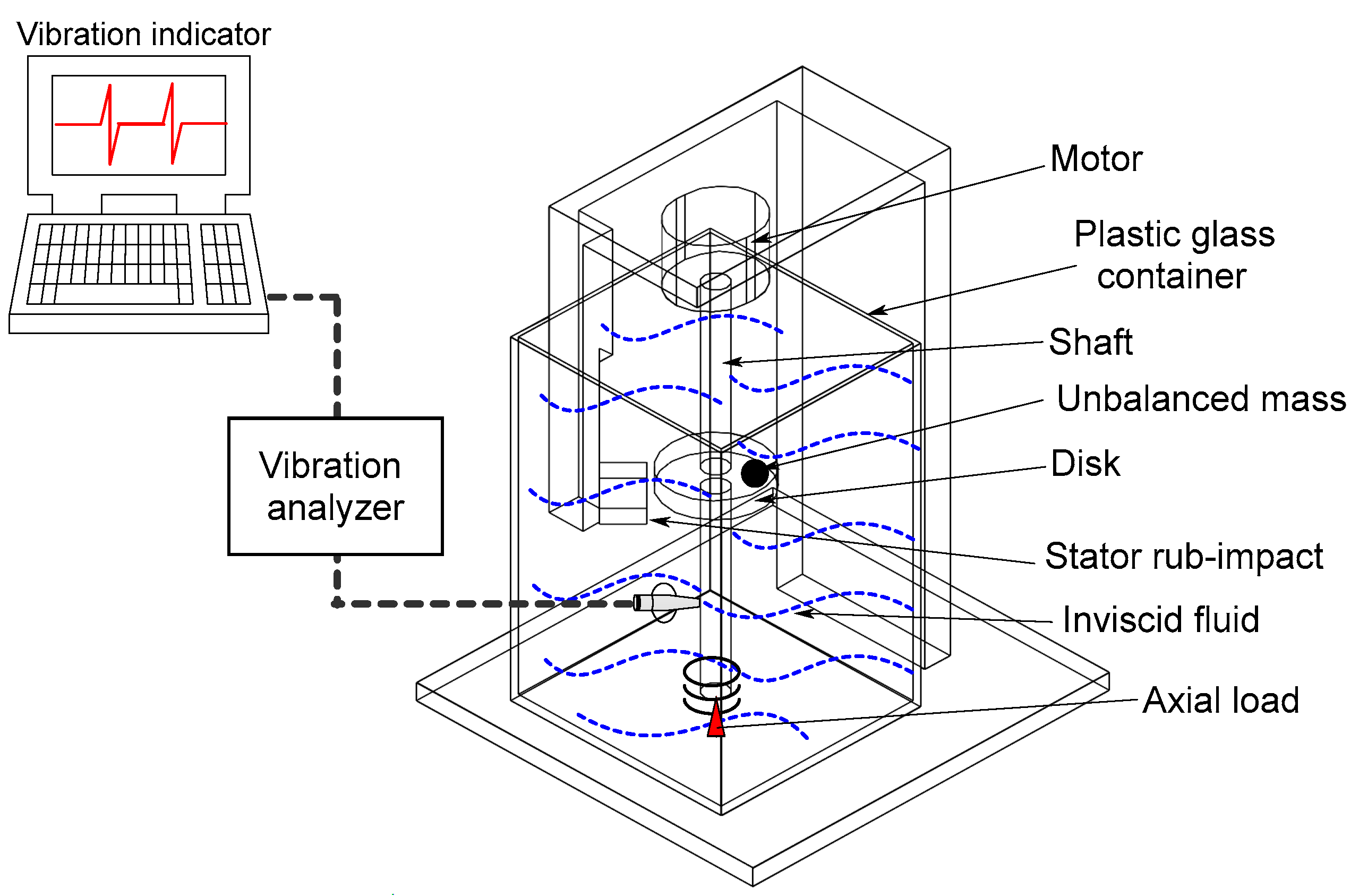
Rotor-Kit 4 offers the possibility of constructing and controlling a high-speed precision rotating machine in a variety of ways. The mechanical tolerances have also been tightened, resulting in more accurate machine behavior modelling. The test rig has been specifically designed for idealized vertical rotor-stator contact measurements in a fluid environment as shown in
Figure 1.
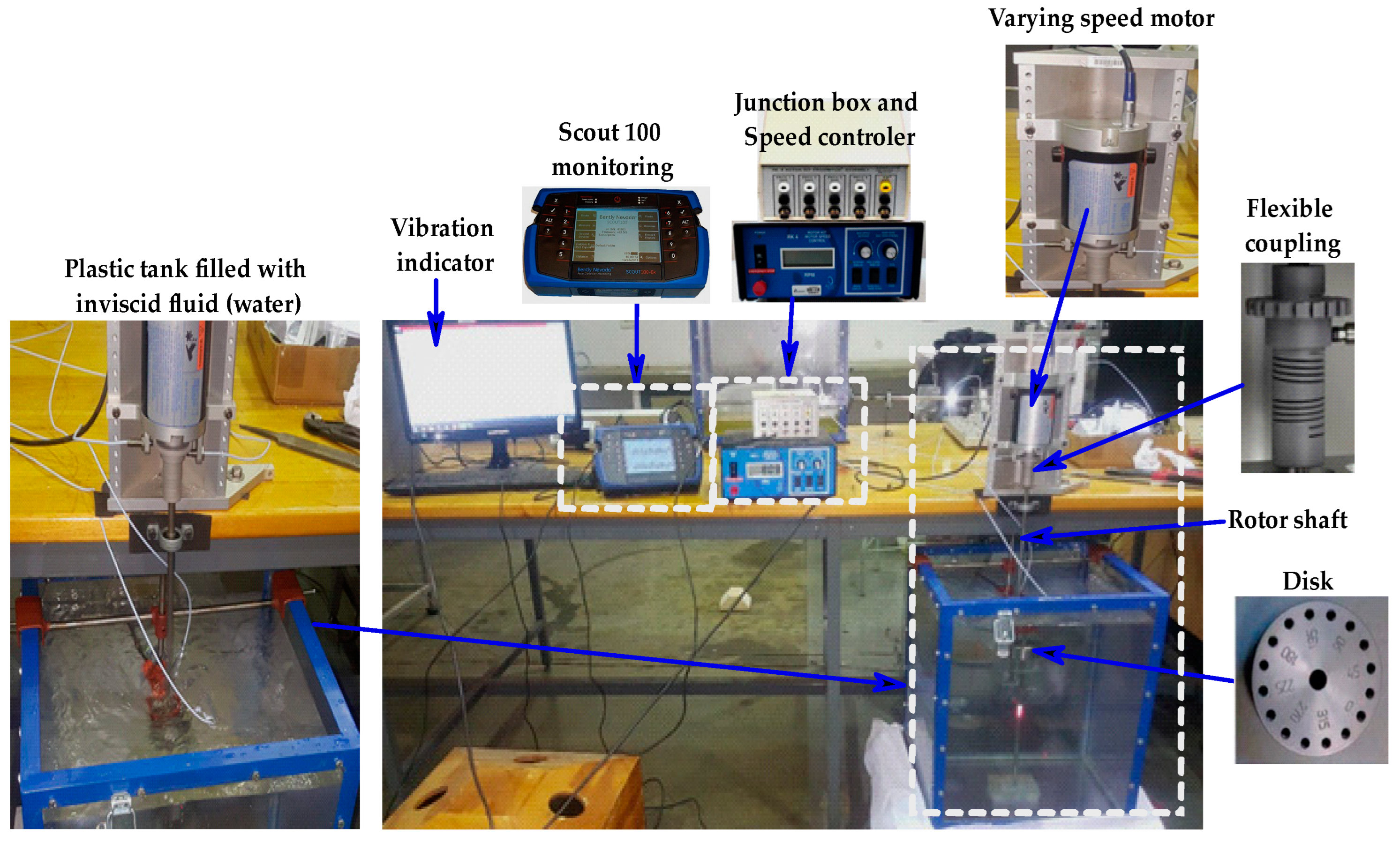
The Bently Nevada Rotor Kit RK4 was used to build and outfit the experiment. The system is likely instrumented with sensors to measure various parameters such as whirl orbits, shaft deflection, and fluctuation frequency during passage through critical speeds. The motor speed controller and electric motor were included in the kit, as well as the proximity assembly and proximity probes in order to control the rotor speed. The rotor is driven through a flexible coupling by an electric motor of 2.5 A, an output power of 250 W, and supported by a load cell placed as a pin support at the bottom of the shaft to create an axial load developed from the rotor motion and whose speed is adjusted by a frequency controller. On the plastic tank’s base, proximity probes are mounted for monitoring the rotor’s movement, and on its sides motor speed control probes are installed for sensing the motor speed as shown in
Figure 2.
Although a laser tachometer was used to verify the accuracy of the rotational speed, the motor has an embedded system that monitors the rotational speed. Under different loads, a machine’s speed can vary significantly, so this method is more accurate than using a default RPM. Aliasing is therefore avoided because the rotational speed of the system will not exceed 1600 rpm. The data were collected at high sample rates to ensure that all relevant frequency components of the signal were captured. The data processing and fault assessment are achieved through data acquisition, data preprocessing, feature extraction, data analysis, data visualization, and result interpretation.
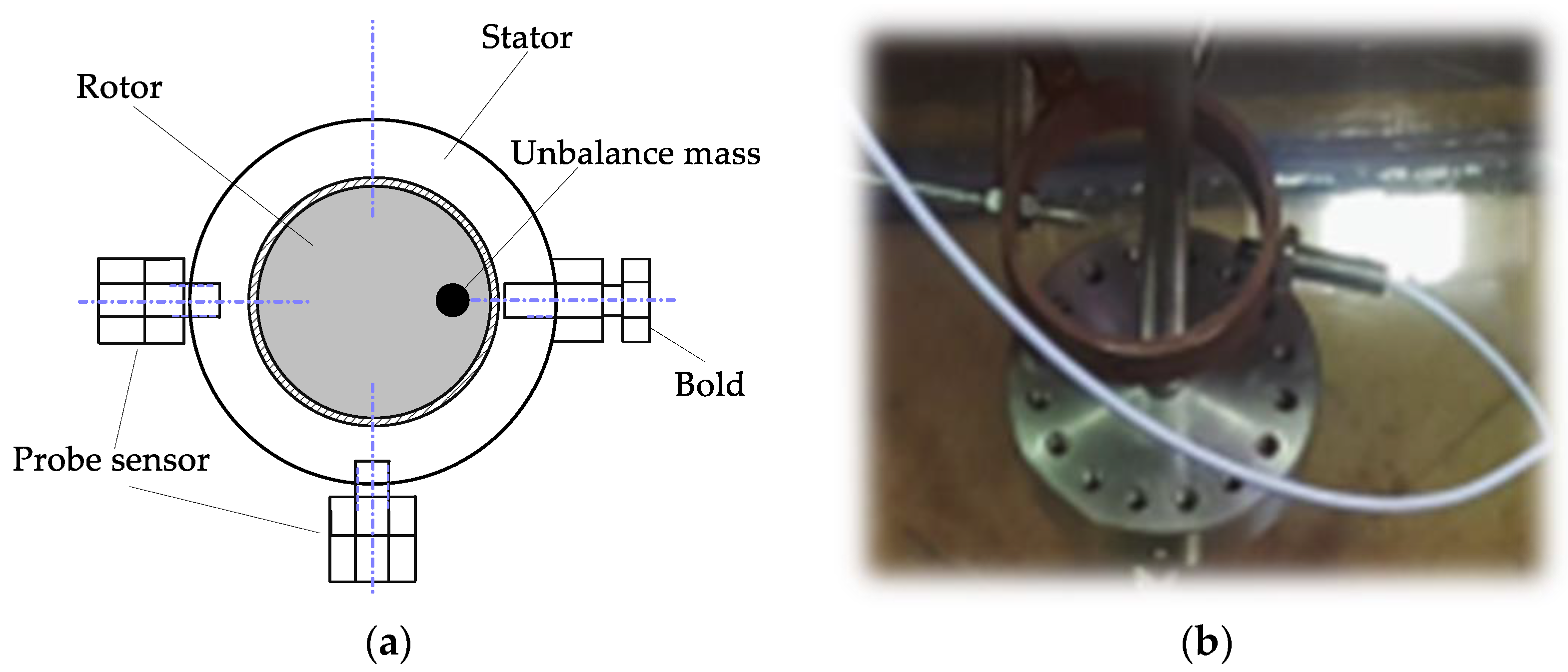
Energy conservation and elastic collisions are the basis of impact theory, a contact screw was used to model a local impact rubbing fault as shown in
Figure 3. These principles are fundamental to the impact theory, which studies the behavior of objects when they collide. In an elastic collision, the total kinetic energy of the colliding objects is conserved, meaning that no energy is lost during the collision.
3. Data Collection
A probe mount was used for holding the proximity sensor probes when a response was taken from the centerline of the motor. The unbalanced mass was simulated by tightening a 3.2 g weight setscrew in the mass wheel. Using the friction housing, a screw was adjusted until it made contact with the shaft, establishing a frictional impact. An electric motor was driven to operate at the experimental speed by a friction screw holder positioned in a specific position. Depending on the experimental conditions, the gap between the rotor and screw can be adjusted. A 70-liter container filled with incompressible fluid (water) was used for the experiments.
To simulate radial rubbing, a rub screw is used to strike the shaft’s radial surface. In the ascent block, probes are used to measure the rotor’s displacement from various shaft points. Due to its usefulness as a monitoring signal for mechanical engineering, vibrations can provide a good indication of a running machine’s condition in this experiment. A vibration signal from the rotor assembly is collected using eddy current sensors placed 90° to each other to measure the lateral deflections at the x and y-directions between the probe tip and rotor target surface. It operates as electromagnetic induction, where a coil of wire generates a magnetic field. When the probe tip is brought close to a conductive target surface, eddy currents are induced in the rotor material. The eddy currents generate their magnetic field, which opposes the original magnetic field, causing a change in the probe coil’s impedance. This change in impedance is then converted into a voltage signal that is used to determine the lateral deflections between the probe tip and rotor target surface. Eddy current sensors receive vibration data that is first preprocessed with an anti-aliasing filter. Moreover, the vibration signals are recorded by a data acquisition computer, displayed, and analyzed using oscillography and a two-channel analyzer. The experiments were conducted with a balanced rotor for the baseline result and an unbalanced mass was introduced for 1600 rpm maximum rotor speed operation.
Table 1 provides a comprehensive list of parameters of the rotor system used during the experiment.
4. Feature Extraction of Experimental Vibration Signal
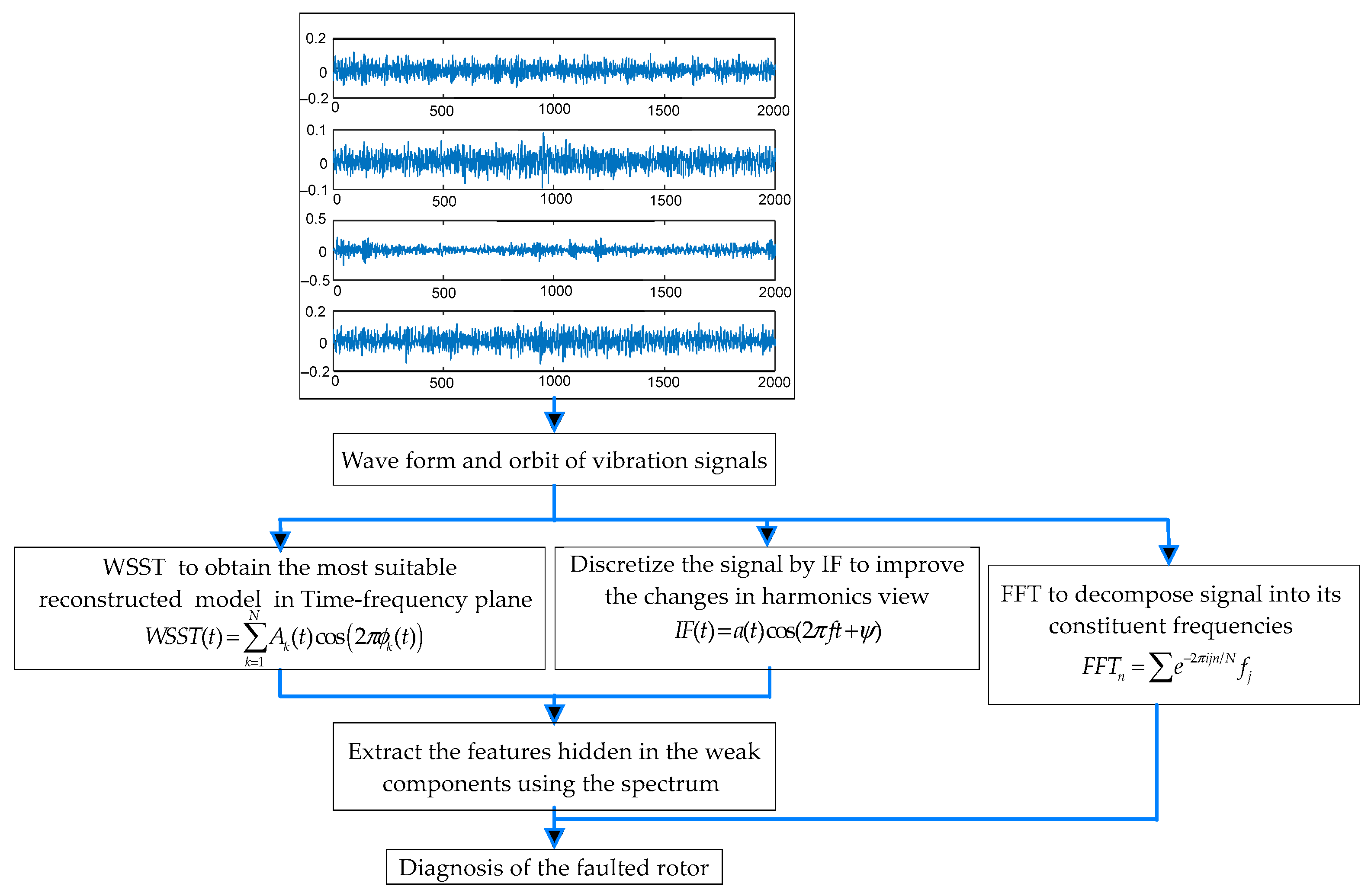
The method of feature extraction described in
Figure 4 is used to identify and diagnose faults in machinery, specifically unbalance and rub faults. The process begins with preprocessing the initial vibration response using the waveform technique to provide a foundation for subsequent signal extraction. The unbalance and rub fault response is typically strongly nonlinear, so the wavelet synchrosqueezing transform (WSST) is used to distinguish features between the two types of faults. The instantaneous frequency (IF) map is then used to analyze changes in the harmonics of the signal. The WSST plots are used to represent the time–frequency view of the signal, which allows for more precise analysis of the vibration signal. The signal is analyzed in two different states to further understand the fault. The experimental results obtained from WSST and the corresponding pseudo-frequency scalogram of the instantaneous frequency (IF) are presented. In addition, the fast Fourier transform (FFT) spectra are used for diagnosing and characterizing the fault, as well as for estimating the length of time before it becomes critical based on its constituent frequencies. By using a combination of methods, this feature extraction method is able to effectively identify and diagnose unbalance and rub faults in machinery, providing valuable information.
Time–frequency analysis is carried out with wavelet synchrosqueezed transforms (WSST) on multicomponent signals. These real-world oscillating-mode signals are frequently represented as the sum of amplitude-modulated and frequency-modulated components. A generic equation describing signals with these types of summed components can be expressed as
An amplitude change is represented by Ak(t), a phase change is represented by ϕk(t), and the signal components are counted by N.
On the basis of the time–frequency representation, the ultimate window width contributes greatly to estimate the instantaneous frequency. It is possible to calculate the ideal window width by minimizing the mean square error (MSE) estimation as long as certain characteristics of the signal and noise are clearly known.
The characteristics, however, cannot be predicted ahead of time. In particular, the estimated bias is determined by the derived IF.
A constant-frequency signal must be considered before a variable-frequency signal can be considered in the formulation below. An amplitude-modulated signal can be considered.
where
f and
ψ are constants, the cosine function has a notable passage through a cycle, as their argument increases as
t increases by
1/
f. As the signal has a period of
1/
f and a frequency
f, the frequency is the reciprocal of the period.
Fast Fourier transforms (FFT) determine the frequency of discrete sine waves from the time domain waveform (amplitude versus time). Measuring vibration frequency, displacement, velocity, and acceleration is typically used to analyze machine vibration.
This way, we can analyze our vibration profile in the time–frequency domain (or spectrum) to capture the strong impacting rotor frequency and prevent damage from highly rubbing contact in an inviscid fluid, A more precise IF estimation is the basis for the WSST method, which is then used to design an improved synchrosqueezing operator.
5. Balance of Rotor System
Throughout the experiment, the rotor speed and the optimum rotor-to-stator clearance will be variable parameters to examine their influence on the rotor system when operating in a fluid medium. The balance is used as the baseline of the experiment to provide a meaningful general scheme for the experimental procedures. During the first experiment of balancing, the shaft traverses the full length of the clearance, transforming into the full annular whirling state.
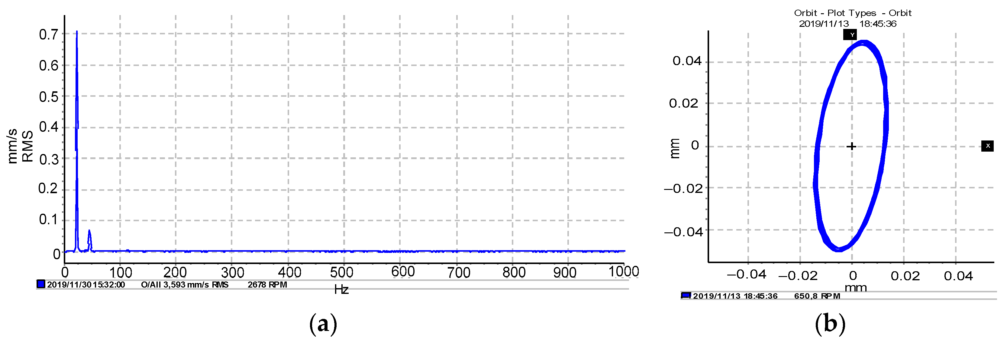
The balancing of the vertical rotor was found to be crucial for stable operation. The rotor synchronous response data captured the lateral mode of the shaft trajectory, which refers to vibrations occurring perpendicular to the axis of rotation. This highlights the importance of balancing the rotor to reduce vibrations and ensure smooth operation. The frequency response of the rotor passing the first critical speed (one resonance) is displayed in
Figure 5a, which indicates that the system’s natural frequency matched the operating frequency, leading to resonance and potential instability. This can be mitigated by ensuring that the system’s components are designed to operate at different frequencies, and the rotational speed is kept within safe limits. Finally,
Figure 5b shows the standard circle mode of appearance in the orbit center, which suggests that the system was relatively stable at that point, and the vibrations were not severe enough to cause significant instability or damage.
6. Unbalance of Rotor System
Unbalance occurs in a rotating machine when the mass centerline and the geometric center do not coincide with each other and generate an excessive centrifugal force on the rotor system that may reduce the life of the machine by damaging its components. A rotor system is almost inextricably linked to the rotor unbalance, so it is essential to ensure that the synchronous vibration amplitudes resulting from unbalanced rotors are acceptable during operating conditions and that the machine can smoothly pass several lateral critical speeds during start-ups and shutdowns. After the balanced rotor experiment, a mass of 96 g was placed at the zero-degree hole of the disk at the middle span of the vertical shaft in order to generate self-centrifugal force when it is in motion and consequently unbalances the rotor system. A vibration analyzer is used to acquire vibration signals.
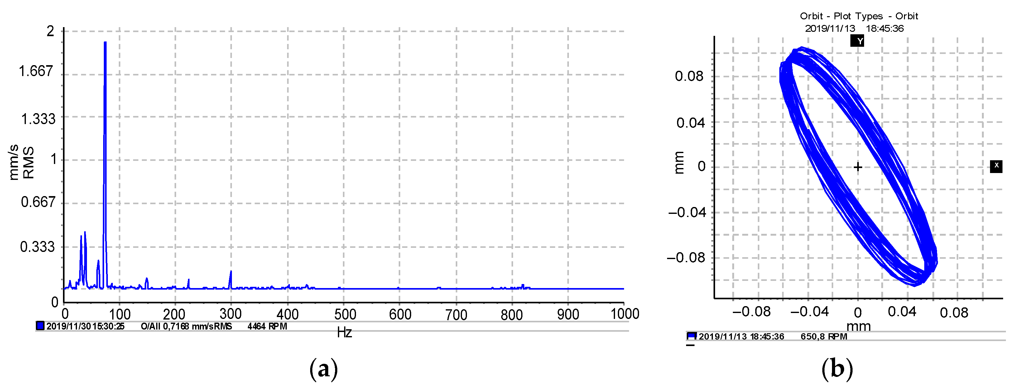
When the rotational energy is transferred to lateral vibration, higher rotor deflections cause a substantial modification in the self-excitation mechanism.
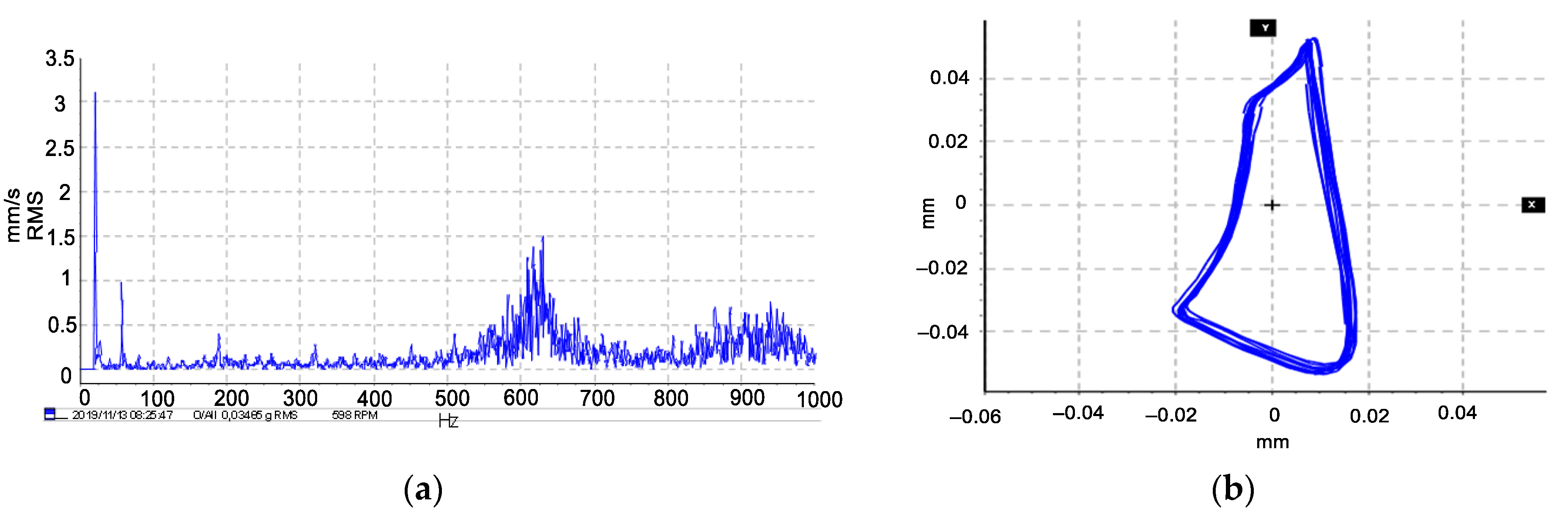
Figure 6a,b presents the rotor response associated with the lateral vibration in pure rotational motion accompanied by a rotor unbalanced state related to the peak of critical speed and orbital vibration creating instability of the rotor system. The high amplitudes in the spectrum indicate that an abnormal condition of two resonance frequencies, such as unbalance, is predominant and has its highest value of 1.917 mm/s, as shown in
Figure 6a. Since rotor unbalances are almost inevitable, it is important to make sure that synchronous vibration amplitudes are acceptable under operational conditions.
7. Unbalance Vertical Rotor in an Inviscid Fluid Domain
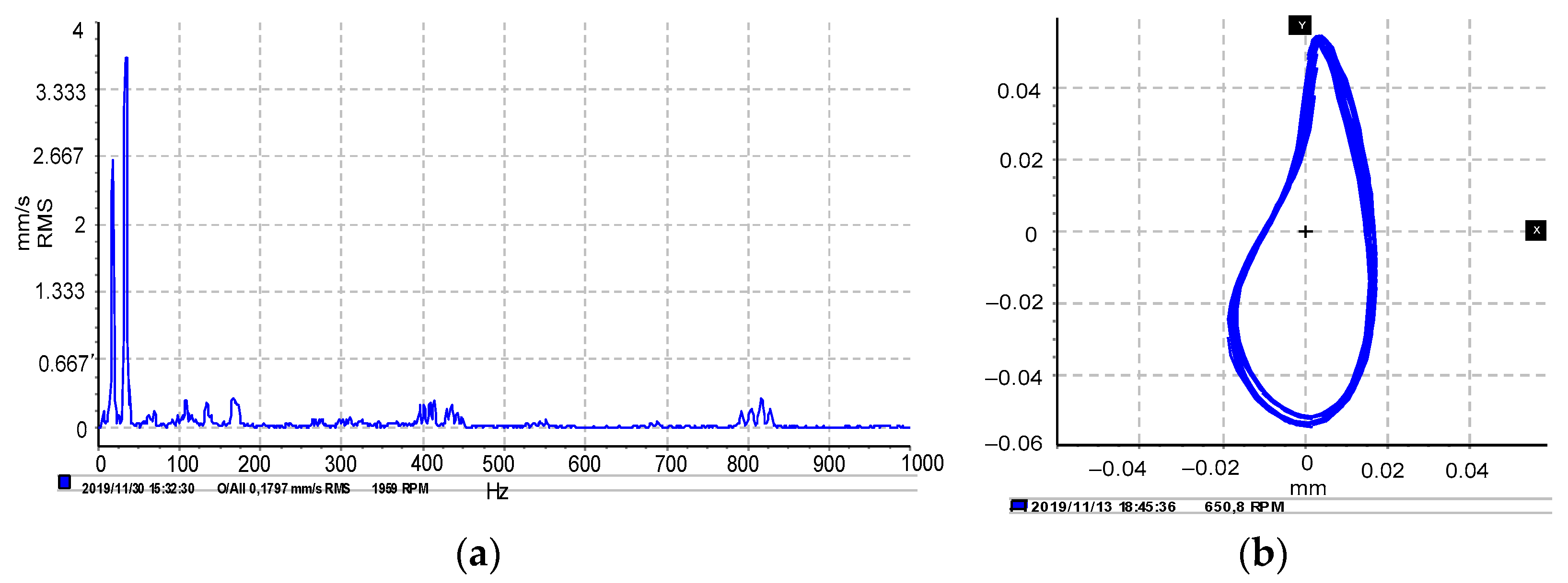
In this section, incompressible and inviscid fluid is introduced into the system, and the stability of the rotor is affected by the rotational speed, the eccentric mass, and fluid force reducing the first resonance speed amplitude.
The results in
Figure 7a suggest that fluid in the system leads to a reduction in vibration amplitude and an increase in damping.
Figure 7b illustrates that fluid flow also causes a decrease in unbalance forces and a slight increase in self-excitation vibration with lower amplitude. Overall, the results indicate that fluid significantly affects the forces acting on the rotor and stator, such as providing a hydrodynamic force that can reduce the unbalance forces and change the natural frequencies of the system.
8. Rotor-Stator Contact System
Unbalanced rotors generate vibration, which may consequently cause the clearance between the rotor and stator to be reduced and create physical contact that damages the components of rotating machines. In this experiment, the rotor-stator full annular rub of a mechanical seal representing the stator was located close to the disk. The seals used in this experiment were tightly fitted to the tank top edge and the contact screw was designed to simulate rubbing faults caused by elastic collisions. A specifically known mass unbalance was then added to the disk at the zero angular orientation and the vibration response of the rub fault.
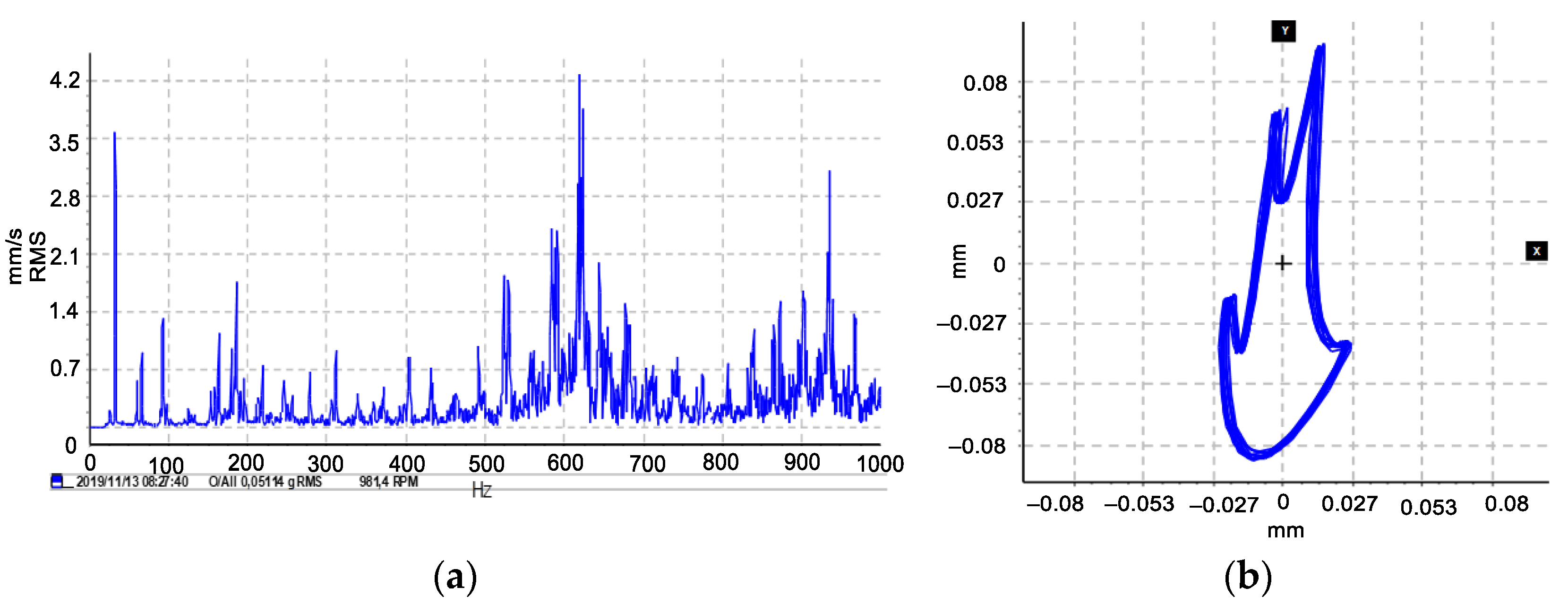
Figure 8a illustrates the rotor motion as a combination of unbalance and rotor-to-stator contact. The rotor-to-stator contact is characterized by the bouncing of harmonic peaks between the rotor and stator. This can be observed as an increase in vibration amplitude at the rubbing frequency.
Figure 8b shows the orbit patterns in the shaft center that display internal loops. This indicates that the rotor is not rotating smoothly as it is being impacted by the stator at irregular intervals. The lack of a clear rotary shape in the orbit patterns further confirms the presence of rotor-to-stator contact in the system. These results suggest that the rotor system is experiencing both unbalance and rotor-to-stator contact issues, which are likely contributing to the observed vibration and potentially causing damage to the system over time.
9. Rotor-Stator Contact in an Inviscid Fluid
In this section, incompressible and inviscid fluid is introduced into the system, and the stability of the rotor is affected by the rotational speed, the eccentric mass, and fluid force reducing the first resonance speed amplitude. Each of these factors contributes to altering the amplitude of the first resonance speed. As the speed of rotation increases, the forces acting on the system also increase, leading to vibration and instability. The presence of an eccentric mass creates an imbalance in the rotating system, which can result in vibration and instability. Additionally, fluid forces influence the stability of the system by reducing the amplitude of the first resonance speed. These forces arise from the interaction between the rotor and the surrounding fluid and have the potential to increase the stability of the system.
In
Figure 9a, a rub on the unbalanced rotor leads to instability in a highly disturbed rotor system. The resistance force created by the fluid’s surface tension reduces the amplitude of vibration and minimizes physical contact. In contrast,
Figure 9b shows that the inviscid fluid in the system reduces the number of disturbances and improves the orbit response.
10. Time–Frequency Analysis
The rotor-stator contact in an inviscid fluid causes the vibration signal to have time-varying frequency components, which can be difficult to detect using traditional frequency analysis methods. Therefore, in this section, the use of the WSST and IF methods is proposed for analyzing experimental vibration signals of rotor-to-stator contact. These methods can effectively separate and analyze non-stationary signals, which are common in vibration signals from rotating machinery. WSST can also provide a high-resolution representation of the frequency and time–frequency characteristics of the signal. While IF represents the rate of change of the phase of the signal with respect to time. It is a measure of the frequency of a signal at a specific point in time, rather than an average frequency over a period of time, which can be useful for identifying specific frequencies or patterns associated with rotor-to-stator contact. Additionally, WSST can also effectively denoise the signal, which can be important for reducing measurement noise and improving the accuracy of the analysis.
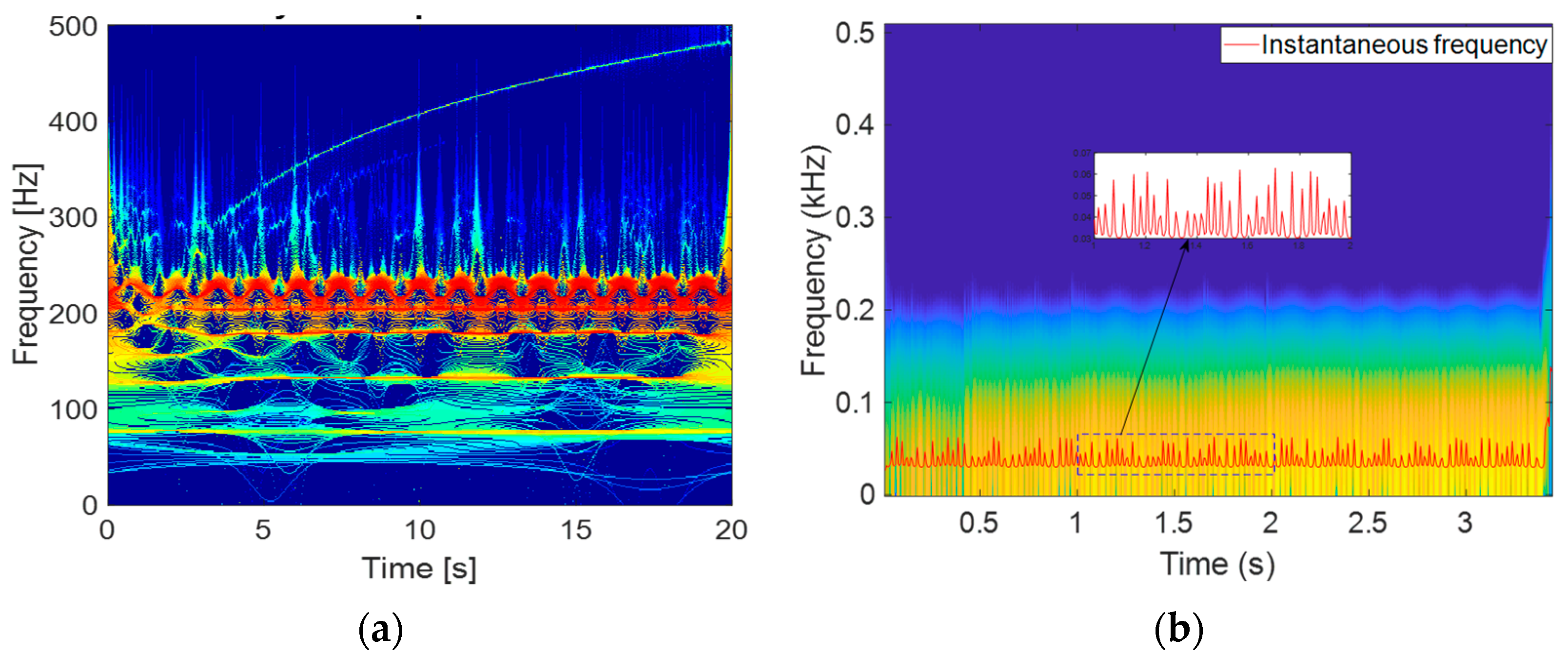
A time–frequency analysis approach is used in this study to decompose a complex signal into its time-varying oscillatory components. This is illustrated in the WSST response in
Figure 10a, which shows a concentration of energy at different frequencies with its mean value around 800 Hz representing the physical contact between the rotor and the stator. The shading at each point on the map indicates the intensity of a signal that resulted from high-frequency component fluctuations induced by contact between the rotor and stator. This signal exhibits multiple lightened peaks and appears to specifically impact the intensity of the frequency component. The rotor-stator contact exhibits an exchange of energy at a higher frequency, as seen in the series of high-frequency spikes in
Figure 10b. The IF map analysis reveals the presence of different oscillating frequency peaks in the system, with the maximum peak observed around 0.23 kHz. This implies that the system experiences oscillations at different frequencies, which can be attributed to the various modes of vibration of the rotor and stator. The random variations observed in the IF map suggest that the oscillations are not strictly periodic but exhibit some degree of randomness. This could be due to the complex interactions between the rotor and stator, which can result in non-linear and chaotic behavior.
The study shows that when fluid is introduced into the system, the WSST response reveals a reduction of the large spectrum signal referring to recurrent contact between the rotor and stator. This is evident in the steady-state mode of appearance on the time–frequency map as seen in
Figure 11a. It is observed that the frequency of shocks in the sampled signal decreases to 230 Hz in energy, with the signal representing self-excitation due to the fluid effect in the system.
Figure 11b illustrates the reduction of the periodicity of rotor-stator contact and the attenuation of successive impacts. This suggests that the introduction of fluid into the system leads to a reduction in the frequency of contact between the rotor and stator, and a decrease in the energy of the resulting shocks. The fluid affects the dynamics of contact between the rotor and stator in the system, and how it may be used to reduce the occurrence of successive impacts.
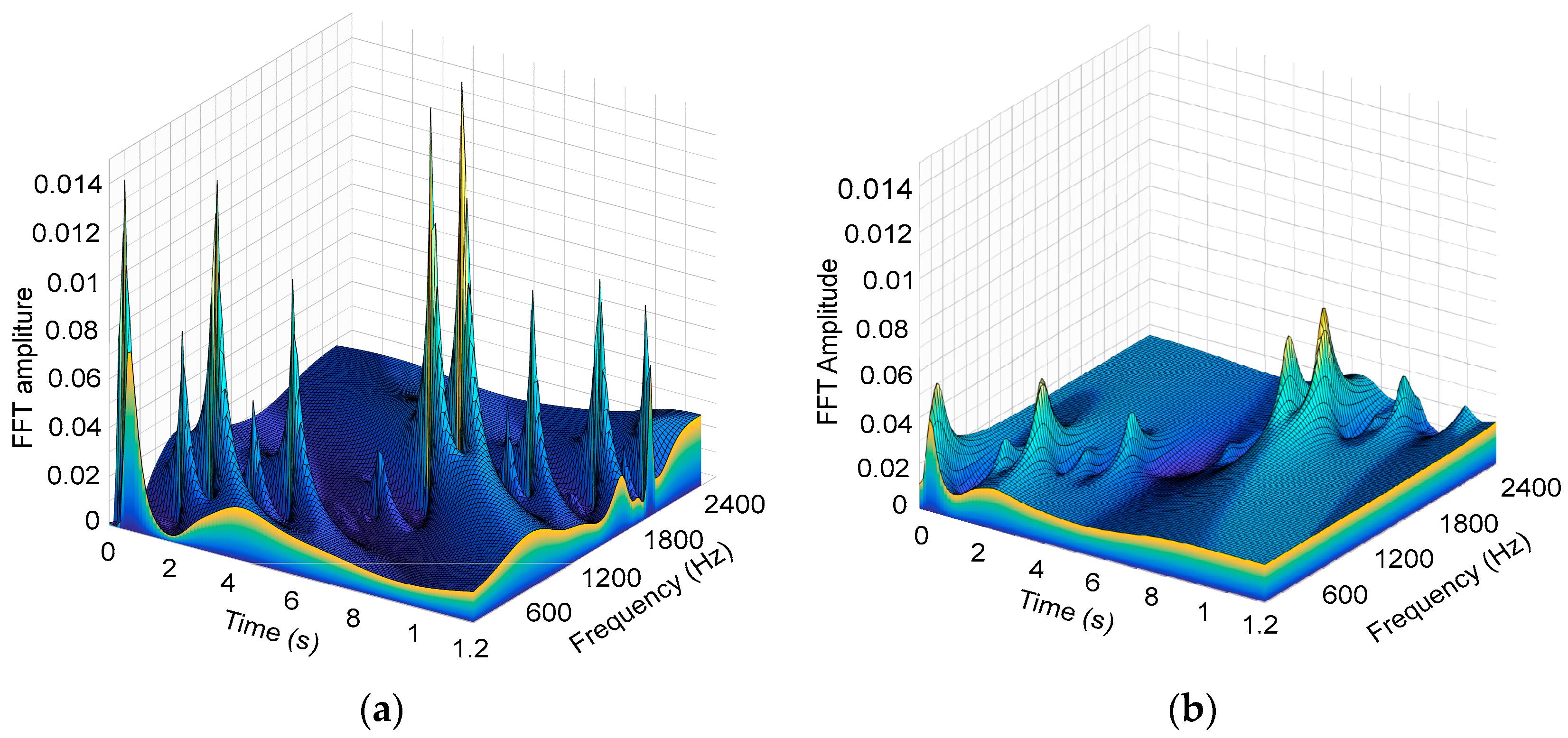
The result of the study indicates that there is evidence of both super and sub-harmonic behavior in the distributed energy when analyzing the fast Fourier transform (FFT) of a set of points in
Figure 12a. The presence of super and sub-harmonic behavior suggests that there is a prominent rotor-stator contact in the spectrum of the signals. The rotor and stator coming into contact at various frequencies may lead to mechanical wear and tear of the components, which can lead to further problems in the system. The energy generated by this contact is distributed across a range of frequencies, with a maximum amplitude of 0.014 FFT. This amplitude indicates the strength of the signal at the corresponding frequency.
Figure 12b shows that the harmonic components of the signal are periodically distributed with shape disturbance and low, irregular energy distribution peaks with 0.06 FFT amplitude. This reflects the impact of fluid properties on a smaller scale of continuous contact throughout the signal spectrum. This suggests that the fluid properties have an effect on the harmonic peaks and shock features in the disturbing signal energy, making them irregular in nature. The dynamics of rotor-stator contact in the presence of fluid properties and how it affects the harmonic peaks and shock features in the signal energy. The results suggest that fluid properties can have a significant impact on the dynamics of rotor-stator contact at a smaller scale, leading to irregular harmonic peaks and shock features in the signal.
11. Discussion
In overall, the novelty of studying a vertical rotor operating in a fluid medium with rotor-stator contact lies in the complexity of the fluid-structure interaction and the potential for non-linear dynamics, as well as the wide range of practical applications, such as in centrifugal pumps, hydraulic turbines, and mixers. The proposed study shows that the presence of rotor-stator contact in a fluid medium leads to unstable flow behavior, which is difficult to predict and analyze using traditional methods. Understanding the dynamics and performance of such systems operating on various fluid properties through different techniques such as computational fluid dynamics can lead to improved designs and greater efficiency.
12. Conclusions
The target of the experimental study of vertical-rotor-stator contact in an inviscid fluid domain was to assess the vertical rotor system with multiple faults and the process of the effect of incompressible and inviscid fluid in the system. Despite the elasticity of the fluid effect that generates self-excitation at low frequencies, the obtained results indicate that the fluid–rotor interaction reduces the dynamic vibration response of the faulted system running below the second critical speed. However, these differences became easier to differentiate when the time–frequency spectral representation was investigated. Regardless of not considering experimental factors such as the axial force, the divergence of values of constant stiffness, the magnitude of recurrent shocks, and not taking into account the gyroscopic effect and excitement of the rotor at its foundation, it was observed that, even after extensive validation of the analytical model studied in [
10], small deviations between the numerical model and experimental results exist. These uncertainties are caused by some numerical errors such as inherent measurement due to the instrumentation and the measuring setup. WSST is an efficient method for improving time–frequency representations, but its application is limited to multicomponent signals containing slightly perturbed and purely harmonic modes. The applicability of the result is a strict set of validation steps of a mathematical model, and the effect on the results is satisfactory for practical engineering applications (i.e., the results can be used for design purposes). The algorithm could be extended to address the progressive degrading of faults of a vertical rotor in a fluid domain where the nature of degradation is continuous and transitions from one fault to another. Other types of data, such as those obtained from acoustic data, could also be extended in future investigations. It is also important to note that, when dealing with continuous and transitioning faults, the algorithm must be able to adapt to the changing nature of the faults. This could be done by incorporating machine learning techniques, such as neural networks, to allow the algorithm to learn from the data and adapt to changing conditions.


