Article

Effect of Geometrical Parameters on Extraction Efficiency of the Annular Centrifugal Contactor

School of Chemical Engineering and Technology, Tianjin University, Tianjin 300072, China
*
Author to whom correspondence should be addressed.
Separations 2021, 8(7), 102; https://doi.org/10.3390/separations8070102
Submission received: 19 June 2021 / Revised: 1 July 2021 / Accepted: 5 July 2021 / Published: 12 July 2021
(This article belongs to the Special Issue 3D Printing in Separation and Reaction Processes)

Abstract

:
The geometrical parameters of annular centrifugal contactors (ACCs) have an important influence on the extraction efficiency. The present work used a home-made 25 mm ACC constructed by 3D printing to investigate the effect of five geometrical parameters on the extraction efficiency. These parameters are annular width (d), clearance height (Hc), rotor inlet diameter (Din), bottom vane number (N), and the bottom vane’s bending direction (S). Central composite design was employed to design the experiment, and the response surface methodology was used to analyze the data. The results show that Hc and Din were positive for efficiency, while d and N were negative. When the bottom vane’s bending direction was the same as the liquid helical flow direction, the efficiency improved compared to the straight vane. It is found that 3 mm d, 5 mm Hc, 6 mm Din, and four clockwise covered vanes are the parameters where the efficiency reached the highest point of 94.5%. We analyzed the interactions between the parameters based on the coefficients of the quadratic equation, and the interactions were not considered in previous studies. This work surprisingly reveals that the effects of the parameters on the extraction efficiency were not independent, and there were interactions between the parameters. The interaction between the rotor inlet diameter and annular width was significant and could not be ignored. These results could serve as a reference for optimizing extraction processes and the design of ACCs.

Graphical Abstract

1. Introduction

Extraction is one of the essential separation techniques in chemical processes. A component is separated from a solvent by transferring the component to an extractant which is immiscible to the solvent. This technique is conducted according to the different solubility of the components in the solvent and the extractant. Mixer-settlers, pulse extraction columns, and annular centrifugal contactors (ACCs) are common instruments used in liquid–liquid extraction [1,2]. The first two types of equipment utilize gravity for separation and result in a slow separation of the light phase from the heavy phase, while an ACC is an efficient device that utilizes centrifugal force. An ACC has the advantages of a small equipment size, a low liquid holdup, a short residence time, and good phase separation performance [3]. Therefore, ACCs have already been used in the nuclear industry, metallurgy, the chemical industry, and biological engineering [4,5,6,7].
The extraction efficiency is the main indicator to evaluate the mass transfer performance of ACCs. Different flow patterns in the ACC lead to different efficiencies. Available studies show that the extraction efficiency could be impacted by the operation parameters, geometrical parameters, and material system [8,9,10]. There have already been many works that studied the effect of operation parameters (total flow rate, phase ratio of two phases, and rotor speed) on efficiency. However, few researchers studied the effect of geometrical parameters, which include annular width (d), clearance height (Hc), rotor inlet diameter (Din), the bottom vane number (N), and the bottom vane’s bending direction (S). Zhao et al. [11] found that the extraction efficiency increased with the annular width and clearance height. Xu et al. [12] showed that the smaller the annular width, the higher the efficiency. Birdwell et al. [13] obtained a lower efficiency when using a curved vane instead of a straight vane, while Leonard et al. [14] and Wardle et al. [15] illustrated that a curved vane could provide higher efficiency. Absolutely, these findings mentioned above have notable differences, and there are no studies that provide a reasonable explanation for the appearance of these differences.
We summarized the experimental design methods of various researchers. It was found that all existing works only study the effect of a single factor on the extraction efficiency once, while the interactions between parameters have never been considered. Therefore, it is necessary to consider the effects of multi-geometrical parameters on the efficiency simultaneously in the experimental design and to explore the influence pattern of geometrical parameters on efficiency. We employed the response surface methodology (RSM) to analyze the interactions between parameters. RSM uses a multivariate quadratic function (MQF) to represent the relationship between variables and response, while the interaction term coefficients characterize the degree of interaction between variables. RSM is widely applied to study extraction processes for its intuitive response surface plots [16,17]. The analysis steps of RSM can be referenced in Silva’s work [18].
This work studied the effect of d, Hc, and Din on the extraction efficiency and investigated the interaction between the three parameters. The experimental system was cyclohexane-isopropanol-water, and central composite design (CCD) was selected to optimize the experimental design. Moreover, this work compared the extraction efficiency obtained from the different bottom vanes (N and S). We analyzed how the geometrical parameters influence the extraction efficiency and provide a reasonable explanation for the discrepancies in the literature above. Our research is of great importance for the design and optimization of ACCs.

2. Materials and Methods

2.1. Chemicals

Isopropanol (>98%) and cyclohexane (>98%) were obtained from Jiangtian Chemical Technology Co., Ltd., Tianjin, China. The solution to be extracted was ten wt.% isopropanol-cyclohexane, and the extractant was water. During the process, the isopropanol in the cyclohexane phase was extracted into the aqueous phase.

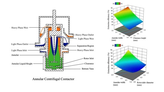
2.2. Annular Centrifugal Contactor

Figure 1 shows a schematic diagram of the ACC. The ACC was made by a UV-curable 3D printer (bene 3) from Nova Smart Technology Co., Ltd., Shenzhen, China. PX-88 resin (PMMA analogue crystalclear UV resin) from Zhemo Technology Co., Ltd., Shenzhen, China, was used as the print material. PX-88 resin has a good solvent resistance and could prevent the ACC from deforming during the experiment. In addition, its transparency enables us to measure the liquid height in the annular region. The dimensions of the home-made ACC are listed below: rotor’s inner diameter was 25.0 mm; rotor’s outer diameter was 28.2 mm; light/heavy phase inlet height was 44.5 mm; separation zone length was 60.0 mm; heavy phase weir diameter was 13.4 mm; light phase weir diameter was 12.0 mm.

2.3. Experimental Design

Design Expert V12 developed by Stat-Ease, Inc., was employed as the design tool. We designed a 3-factor, 5-level CCD experiment for continuous parameters (d, Hc, and Din). Table 1 shows the correspondence between the CCD’s coding levels and the values of parameters. In addition, the discontinuous parameters (N and S) were experimented with individually.

2.4. Methods

Figure 2 shows the schematic diagram of the experimental apparatus. Firstly, the heavy phase (water) was pumped into the ACC at 60 mL·min−1. Secondly, the light phase (10 wt% isopropanol-cyclohexane) was pumped in with 30 mL·min−1 after the liquid flowed out of the heavy phase outlet. At 6 min after starting the experiment, the isopropanol concentration in the light phase outlet stream did not change, and we considered the process had reached a steady state. This measurement was consistent with the conclusion mentioned by Kadam et al. [19] that the extraction process would obtain the steady state after three times the residence time. Thirdly, after reaching the steady state, we recorded the annular liquid height (ALH) and analyzed the composition of the light phase outlet product. Finally, we kept the motor running and drained the annular liquid from the bottom discharge port, and its volume was the holdup volume (Vm) in the annular region. Each experiment was repeated 3 times. The motor speed was set to 2500 r·min−1 for all experiments and was rotated in a clockwise direction.
An Agilent 6820 gas chromatograph was used with a flame ionization detector at 120 °C and an Agilent SE-54 capillary column with dimensions of 30 m × 0.32 m × 0.25 μm. Split injections were made at 100 °C with a split ratio of 50:1.
The Taylor number (Ta) is a dimensionless number proposed by Taylor and defined as the ratio of the centrifugal force to viscous force, which reflects the flow pattern of the fluid [20]. Equation (1) can calculate the Ta of fluid in the annular region, and Equations (2) and (3) provide the critical Taylor number (TaCr) with the axial flow [21]. In this experiment, the Taylor number was 1.28 × 10⁷–5.91 × 10⁷, and the corresponding critical Taylor number was 4.83 × 10³–4.46 × 10³. Thus, the Ta is more significant than 1000 times the TaCr, indicating that the flow patterns in the annular region are in turbulent Taylor flow.
Ta = riod2ω2/ν2
TaCr = 1708 + 27.15Rez
Rez = du/ν
where Ta is the Taylor number of the fluid; TaCr is the critical Taylor number; rio is the outer radius of the rotor; d is the annular width; ω is the angular velocity of the rotor; ν is the kinematic viscosity of the fluid; Rez is the axial flow Reynolds number in the annular region; u is the liquid flow velocity along the axial direction in the annular region.

2.5. Extraction Efficiency

The extraction efficiency is the evaluation index of the mass transfer performance of ACCs, and the higher the efficiency, the better the mass transfer performance. The extraction efficiency defined by the Murphree equation is shown in Equation (4) [22]. We took the average of three experiments as the extraction efficiency under a certain condition.
EO = (wO,outwO,in)/(wO,eqwO,in)
where EO is the extraction efficiency of the organic phase (%); wO,in and wO,out are the isopropanol mass fractions in the light phase inlet stream and outlet stream, respectively; wO,eq is the mass fraction of isopropanol in the organic phase when the extraction process reaches equilibrium.

3. Results and Discussion

Error analysis of the data obtained through three replicate experiments showed that the relative error of the extraction efficiency value was 0.920%.
We obtained Equation (5) using the multivariate quadratic function (MQF) in the response surface methodology (RSM) to fit the data of extraction efficiency. Table 2 shows the ANOVA for the Equation (5), where the p-value of the equation is less than 0.0001, which implies the equation is significant, and there is only a 0.01% chance that such an F-value (19.0) could occur due to noise. Furthermore, the regression coefficient of Equation (5) is 0.945, indicating that the equation fits the data well. Figure 3 shows the response surface of equation (5), where the x-y plane represents the experimental interval for any two of the three parameters, and the z-axis means the EO. The fluctuation in the response surface indicates the variation in the efficiency.
ALH (i.e., annular liquid height) and Vm (i.e., holdup volume) were measured to explain the effect of geometrical parameters on EO, and the data are shown in Figure 4 and Figure 5, respectively. The error of ALH and Vm mainly comes from the measurement. In this study, the absolute error of ALH is 0.3 mm, and Vm is 0.1 mL. The change in the geometrical parameters caused a shift in the phases’ flow pattern, consequently changing the ALH and Vm, which caused the variability of the EO.
EO = 89.7 − 0.631d + 1.98Hc − 2.93Din − 0.418d*Hc − 1.46d*Din − 0.0554Hc*Din + 0.926d2 + 0.118Hc2 + 1.04Din2

3.1. Effect of Geometrical Parameters on Extraction Efficiency

3.1.1. Annular Width

Figure 3a,c show that EO decreased significantly as the annular width increased from 3.0 to 5.0 mm, regardless of the value of the clearance height and rotor inlet diameter. Notably, the decreasing speed of EO slows down when the annular width approaches 5 mm. Figure 4a shows that ALH decreases significantly from 14.8 to 6.9 mm, and Figure 5a shows Vm increases slightly from 9.8 to 10.0 mL as the annular width increases.
The reason for the change in EO with the annular width can be summarized as the following two points: (1) As the annular width increased, the Vm increased. The mixing time of the annular liquid was proportional to the Vm. Therefore, the mixing time became longer, and the extractant extracted more components, which improved mass transfer performance. (2) The ALH decreased when the annular width increased, leading to unit volume power (P/V) reduction. Thus, the mass transfer coefficient decreased, which was detrimental to mass transfer.
Kadam et al. [17] had given the mass transfer coefficient (kca) of the centrifugal extraction as a function of P/V, as shown in Equation (6).
kca = 0.64(P/V)0.22
Arafat et al. [23] calculated the useful work (P) conducted by the rotor in Equation (7). Equation (8) could be used to calculate the rotor worked area’s volume (V).
P = 0.0261Hrio3.75 j2.75ρ0.75 (μ/d)0.25
V = πH[(rio + d)2rio2]
The adjustment factor j in Equation (7) can be obtained by Equations (9) and (10).
j = 0.0554(lgNRe) + 1.368   (3.0 × 10³ < NRe < 1.0 × 10⁶)
NRe = 2jρωriod/μ
where kca is the mass transfer coefficient; P is the useful work conducted by the rotor on the liquid in the annular region; V is the volume of fluid in the area of direct rotor work, i.e., the volume of liquid in the annular region after removing the clearance liquid at the bottom of the rotor; H is the liquid height of V in the annular region; rio is the outer radius of the rotor; j is the adjustment factor; ρ is the density of the mixed fluid; μ is the viscosity of the mixed fluid; d is the width of the annular region; NRe is the Reynolds number of the fluid in the annular region; ω is the angular velocity of the rotor.
With the annular width increased from 3.0 to 5.0 mm, the mixing time increased by 2.04%, while the kca decreased by 12.4%, which noted that the negative impact caused by the increase in the annular width dominated the efficiency. Therefore, the EO dropped when the annular width increased. We predict through the MQF that the positive impact of the mixing time would dominate the efficiency when the d is more than 5.16 mm. However, due to the size limitation of the 3D printing equipment, the EO at larger annular widths was not investigated.
In this subsection, we explain how the geometrical parameters influence the EO from the perspective of mass transfer theory. The introduction of ALH and Vm into the EO’s study could help us to understand the mass transfer process in the ACC.

3.1.2. Clearance Height

Figure 3a,b show that the EO reaches the maximum when the clearance height is 5 mm. The growth rate of EO with the clearance height is the same for different annular widths and rotor inlet diameters. As shown in Figure 4b and Figure 5b, with the clearance height increasing from 3.0 to 5.0 mm, the increment of the ALH has the same value as the increment of the clearance height, and the Vm increases obviously by 22.3%.
As the clearance height increased, the ALH increased, but the H remained unchanged. The mass transfer coefficient remained the same according to Equations (6)–(10). Notably, the increase in Vm significantly prolonged the mixing time of the two-phase liquid in the annular region and intensified the mass transfer process. Therefore, the EO increased with the clearance height.
By analyzing the Vm and ALH, we found that the change in the clearance height had no effect on kca, but could affect EO by changing Vm. Therefore, a larger clearance height is beneficial to EO.

3.1.3. Rotor Inlet Diameter

From Figure 3c, we find that the annular width governs the effect of the rotor inlet diameter on the EO. When the annular width is 3.0 mm, the EO increases by 6.18% significantly with the rotor inlet diameter increases. However, the EO only increases by 2.99% when the annular width is 4.0 mm. The increasing speed slows down compared with 3.0 mm. EO maintains a value of 86.0% as the annular width reaches 5.0 mm. ALH and Vm data are shown in Figure 4c and Figure 5c, respectively.
The ACC draws the fluid into the rotor, relying on the rotor’s self-priming force caused by the pressure differential between the rotor inlet and the cavity inside the rotor. The greater the self-priming force, the more easily annular fluid is pulled into the rotor. Hence, the ALH and Vm reduce. Bernstein et al. [24] found the self-priming force of the rotor was negatively related to the rotor inlet diameter by theoretical derivation.
When the annular width was 3.0 mm, the rotor’s self-priming force decreased as the rotor inlet diameter increased, which led to difficulty in drawing the two-phase liquid into the rotor. The accumulation of Vm prolonged the mixing time of the two-phase liquid, and the extraction efficiency rose. However, an increase in the annular width would cause the ALH to decrease. The rotor inhaled more gas because of a lower liquid level, weakening the effect of the rotor inlet diameter on the efficiency. Therefore, the rise in EO when the annular width is 4.0 mm was less than 3.0 mm. If the annular width reached 5.0 mm, the ALH was only 6.9 mm. The rotor inhaled a large amount of gas. At this time, the pressure differential had no changes with the rotor inlet diameter increases. Thus, the Vm did not change, and the EO was maintained at 86.0%.
Although the increase in the rotor inlet diameter is beneficial for the EO, the level of the annular width affects the degree of the EO rise. This is due to the interaction between the annular width and the rotor inlet diameter. We will explain this interaction in Section 3.2 using a response surface model.

3.1.4. Bottom Vane

Figure 6 describes the five bottom vanes employed to investigate the effects of the vane’s shape and number on the extraction efficiency. The result (Table 3) shows 4CV has the highest EO of 94.5%. Comparing with 6V and 8V, the EO of 4V increases by 2.3% and 5.2%, respectively.
Wardle et al. [25] found that the bottom vane significantly affected the Vm through computational fluid dynamics (CFD) simulation and experimental study. The function of the bottom vane is to break the liquid helical flow in the annular region and direct the liquid flow to the rotor inlet through vortices. 4V is the most commonly used type of vane in centrifugal contactor studies [26,27,28]. Compared with 4V, the bending direction of 4CV is the same as the liquid helical flow, which leads 4CV to enhance the fluid resistance flow to the rotor inlet. Therefore, the guiding role of 4CV was weakened, and the fluid was unfavorable to flow to the rotor inlet. 4CV had a higher Vm and a longer mixing time than 4V. Thus, when 4CV was used instead of 4V, the EO rose.
4ACV had an opposite direction to the liquid spiral flow, which weakened the flow resistance at the bottom of the ACC and enhanced the bottom vane’s guiding effect. 4ACV promoted the fluid flow to the rotor inlet. Thus, the Vm was decreased, and the mixing time of the two-phase liquid was shortened. 4ACV lead to a reduction in EO.
The variation in EO with the bottom vane number is shown in Table 3. The addition of the bottom vane number enhanced vanes’ guiding effect. The liquid was favorable to the flow toward the rotor inlet. Hence, 8V had a lower Vm than 4V and 6V, and the mixing time of 8V was shorter. Consequently, the EO decreased with the increase in the bottom vane number.
We compared the EO of five different structures of bottom vanes in this subsection and interpreted the results by analyzing the flow of the fluid inside the ACC. For the straight vanes discussed in the current work, the EO is higher with a lower number of bottom vanes. We find that 4CV could raise the EO better than 4V, while 4ACV, which is opposite to the flow direction, was not conducive to the EO. This conclusion could explain why the results of Birdwell and Leonard are different, as, although they used the same bending direction of the bottom vane, the fluid flow directions were different.

3.2. Response Surface Model Explanation of Each Factor Affecting the EO

As shown in Equation (5), the RSM (i.e., response surface methodology) represented the relationship between the geometrical parameters and EO by an MQF (i.e., multivariate quadratic function). This method reflects the direction and magnitude of geometrical parameters’ effect on EO in the form of regression coefficients from statistical principles. Thus, MQF provides a new way of thinking by studying the change rate of geometrical parameters relative to EO and then giving a statistical interpretation for the experimental results. This idea is also one of the advantages of applying the RSM to assist the experimental design in this study.
The first derivatives of the EO in Equation (5) concerning three geometrical parameters were obtained separately. The first derivatives represented the slope of the curves. As shown in Equations (11)–(13), we used the second derivative of its first derivative with respect to another geometric parameter to indicate how another parameter affected the slopes between curves. The closer the second derivative was to zero, the more independent the effect of the parameter on the EO.
None of the second derivatives in the equations above are zero, which shows that the effect of each geometric parameter on the EO is not independent. There is an interaction between the parameters. Single-factor experiments cannot analyze the interactions between parameters, while fitting the interactions into the correlation equation is one of the advantages of RSM [29].
∂EO/∂d = 1.85d − 0.418Hc − 1.46Din − 0.631
2EO/(∂d∂Hc) = −0.416
∂EO/∂Hc = 0.236Hc − 0.418d − 0.0554Din + 1.98
2EO/(∂Hc∂Din) = −0.0554
∂EO/∂Din = 1.04Din − 1.46d − 0.0554Hc − 2.93
2EO/(∂Din∂d) = −1.46
Figure 4 displays that the EO varies with each factor. The slope change between the curves is not significant in Figure 4a,b, which correspond to the second derivatives close to zero in Equations (11) and (12). Therefore, the interactions of dHc and HcDin are weak. However, the second derivative of EO on Dind is −1.48, indicating the variation in d interferes with the effect of Din on EO significantly. This result consists of the mass transfer theory analysis in Section 3.1.3.
We used the regression coefficients of the MQF to explain the interactions between geometrical parameters, demonstrating the applicability of the RSM in the study of the multiparametric effects of EO.

4. Conclusions

The present work studied the EO of an ACC with different geometrical parameters. We dissected the reasons for the effects of these parameters based on mass transfer theory and analyzed the interactions between the parameters according to the MQF.
We found that the EO is proportional to the clearance height and rotor inlet diameter. However, the effect of the rotor inlet diameter on EO is limited by the annular width. The EO is inversely proportional to the annular width and bottom vane’s number. Moreover, the MQF predicted that the EO increases with the annular width when the annular width is more than 5.16 mm. The EO of 4CV is higher than 4V because 4CV has the same bending direction as the fluid flow. In contrast, the bending direction of 4ACV is opposite to the fluid flow, and the EO is lower than 4V. Analysis of the MQF indicates that each parameter’s effect on the EO is not independent. The interaction of Dind is more substantial, and we must consider it. This suggests that we should consider the interactions between the parameters comprehensively when conducting the experimental design or equipment design to determine a reasonable range of parameter values.
Due to the limitation of the existing 3D printing equipment in the laboratory, we did not investigate a wider range of geometrical parameters. However, the results in this work still show that the ACC’s geometrical parameters influence the EO significantly, and there are interactions between parameters. These results could provide a reference for the design of ACCs and the optimization of the extraction process.

Author Contributions

Conceptualization, X.Y. and R.W.; methodology, Y.S. and J.T.; software, Y.S.; validation, Y.S.; formal analysis, Y.S. and J.T.; investigation, Y.S.; resources, X.Y. and R.W.; data curation, Y.S.; writing—original draft preparation, Y.S.; writing—review and editing, Y.S., J.T. and R.W.; visualization, Y.S.; funding acquisition, R.W. All authors have read and agreed to the published version of the manuscript.

Funding

This research received no external funding.

Institutional Review Board Statement

Not applicable.

Informed Consent Statement

Not applicable.

Data Availability Statement

Data are contained within the article.

Acknowledgments

We acknowledge Jiangsu Seven Continents Green Chemical Co., Ltd. for their financial support.

Conflicts of Interest

The authors declare no conflict of interest.

References

  1. Ramaswamy, S.; Huang, H.J.; Ramarao, B.V. Separation and Purification Technologies in Biorefineries, 1st ed.; John Wiley & Sons Ltd.: Hoboken, NJ, USA, 2013; pp. 61–70. [Google Scholar]
  2. Manousi, N.; Plastiras, O.E.; Kalogiouri, N.P.; Zacharis, C.K.; Zachariadis, G.A. Metal-Organic Frameworks in Bioanalysis: Extraction of Small Organic Molecules. Separations 2021, 8, 60. [Google Scholar] [CrossRef]
  3. Vedantam, S.; Joshi, J.B. Annular Centrifugal Contactors—A Review. Chem. Eng. Res. Des. 2006, 84, 522–542. [Google Scholar]
  4. Duan, W.H.; Sun, T.X.; Wang, J.C. An Industrial-Scale Annular Centrifugal Contactor for the TRPO Process. Nucl. Sci. Tech. 2018, 29, 1–9. [Google Scholar] [CrossRef]
  5. Davis, M.W.; Weber, E.J. Liquid-Liquid Extraction between Rotating Concentric Cylinders. Ind. Eng. Chem. Res. 1960, 52, 929–934. [Google Scholar] [CrossRef]
  6. Xu, J.Q.; Duan, W.H.; Zhou, X.Z.; Zhou, J.Z. Extraction of Phenol in Wastewater with Annular Centrifugal Contactors. J. Hazard. Mater. 2005, 131, 98–102. [Google Scholar] [CrossRef] [PubMed]
  7. Holeschovsky, U.B.; Cooney, C.L. Quantitative Description of Ultrafiltration in A Rotational Filtration Device. AIChE J. 1991, 37, 1219–1226. [Google Scholar] [CrossRef]
  8. Cao, S.; Duan, W.H.; Wang, C.Q. Effects of Structure Parameters on the Hydraulic Performance of the 20 Annular Centrifugal Contactor. Energy Procedia 2013, 39, 461–466. [Google Scholar] [CrossRef] [Green Version]
  9. Nicholas, B.; Wyatt, T.J.; O’Hern, B.S. Drop-Size Distributions and Spatial Distributions in an Annular Centrifugal Contactor. AIChE J. 2013, 59, 2219–2226. [Google Scholar]
  10. Chen, H.L.; Wang, J.C.; Duan, W.H. Hydrodynamic Characteristics of 30% TBP/Kerosene-HNO3 Solution System in an Annular Centrifugal Contactor. Nucl. Sci. Tech. 2019, 30, 47–58. [Google Scholar] [CrossRef]
  11. Zhao, M.M.; Cao, S.; Duan, W.H. Effects of Some Parameters on Mass-Transfer Efficiency of a Φ20 mm Annular Centrifugal Contactor for Nuclear Solvent Extraction Processes. Prog. Nucl. Energy 2014, 74, 154–159. [Google Scholar] [CrossRef]
  12. Xu, Y.; Tang, K.; Bai, Z.S.; Wang, H.L. Hydrodynamic and Mass-Transfer Characteristics of Annular Centrifugal Contactors on the Caprolactam Recovery from Waste Liquor. Appl. Mech. Mater. 2013, 330, 792–798. [Google Scholar] [CrossRef]
  13. Birdwell, J.F.; Anderson, K.K. Evaluation of Mass Transfer Performance for Caustic-Side Solvent Extraction of Cesium in A Conventional 5-cm Centrifugal Contactor; Oak Ridge National Laboratory: Oak Ridge, TN, USA, 2002.
  14. Leonard, R.A.; Regalbuto, M.C.; Aase, S.B.; Arafat, H.A.; Falkenberg, J.R. Hydraulic Performance of a 5-cm CINC Contactor for Caustic-Side Solvent Extraction; Argonne National Laboratory: Oak Ridge, TN, USA, 2002.
  15. Wardle, K.E.; Allen, T.R.; Anderson, M.H.; Swaney, R.E. Experimental Study of the Hydraulic Operation of an Annular Centrifugal Contactor with Various Mixing Vane Geometries. AIChE J. 2010, 56, 1960–1974. [Google Scholar] [CrossRef]
  16. Attimarad, M.; Elgorashe, R.E.E.; Subramaniam, R.; Islam, M.M.; Venugopala, K.N.; Nagaraja, S.; Balgoname, A.A. Development and Validation of Rapid RP-HPLC and Green Second-Derivative UV Spectroscopic Methods for Simultaneous Quantification of Metformin and Remogliflozin in Formulation Using Experimental Design. Separations 2020, 7, 59. [Google Scholar] [CrossRef]
  17. Faraji, N.; Zhang, Y.; Ray, A.K. Optimization of Lactoperoxidase and Lactoferrin Separation on an Ion-Exchange Chromatography Step. Separations 2017, 4, 10. [Google Scholar] [CrossRef] [Green Version]
  18. Silva, V. Statistical Approaches with Emphasis on Design of Experiments Applied to Chemical Processes, 1st ed.; BoD–Books on Demand: Norderstedt, Germany, 2018; pp. 157–166. [Google Scholar]
  19. Kadam, B.D.; Joshi, J.B.; Koganti, S.B.; Patil, R.N. Hydrodynamic and Mass Transfer Characteristics of Annular centrifugal contactors. Chem. Eng. Res. Des. 2007, 86, 233–244. [Google Scholar] [CrossRef]
  20. Taylor, G.I. Stability of a Viscous Liquid Contained Between Two Rotating Cylinders. Philos. Trans. R. Soc. Lond. A 1923, 223, 289–343. [Google Scholar]
  21. Chandrasekhar, S. The Stability of Spiral Flow between Rotating Cylinders. Proc. R. Soc. London. Ser. A Math. Phys. Sci. 1962, 263, 57–91. [Google Scholar]
  22. Wardle, K.E. Summary Report on Liquid-Liquid Contactor Scoping Experiments and Validation Test Case Definition; Argonne National Laboratory: Oak Ridge, TN, USA, 2012.
  23. Arafat, H.A.; Hash, M.C.; Hebden, A.S.; Leonard, R.A. Characterization and Recovery of Solvent Entrained during the Use of Centrifugal Contactors; Argonne National Laboratory: Oak Ridge, TN, USA, 2001.
  24. Bernstein, G.J.; Grosvenor, D.E.; Lenc, J.F.; Levitz, N.M. Development and Performance of a High-Speed, Long-Rotor Centrifugal Contactor for Application to Reprocessing LMFBR Fuels; Argonne National Laboratory: Oak Ridge, TN, USA, 1973.
  25. Wardle, K.E.; Allen, T.R.; Swaney, R. Computational Fluid Dynamics (CFD) Study of the Flow in an Annular Centrifugal Contactor. Sep. Sci. Tech. 2008, 41, 2225–2244. [Google Scholar] [CrossRef]
  26. Wardle, K.E. FY12 Summary Report on Liquid-Liquid Contactor Experiments for CFD Model Validation; Argonne National Laboratory: Oak Ridge, TN, USA, 2012.
  27. Wardle, K.E.; Allen, T.R.; Anderson, M.H. Analysis of the Effect of Mixing Vane Geometry on the Flow in an Annular Centrifugal Contactor. AIChE J. 2009, 55, 2244–2259. [Google Scholar] [CrossRef]
  28. Birdwell, J.F.; Anderson, K.K. Evaluation of 5-cm Centrifugal Contactor Hydraulic and Mass Transfer Performance for Caustic-Side Solvent Extraction of Cesium; Argonne National Laboratory: Oak Ridge, TN, USA, 2001.
  29. Le, A.V.; Parks, S.E.; Nguyen, M.H.; Roach, P.D. Optimised Extraction of Trypsin Inhibitors from Defatted Gac (Momordica Cochinchinensis Spreng) Seeds for Production of a Trypsin Inhibitor-Enriched Freeze Dried Powder. Separations 2019, 6, 8. [Google Scholar] [CrossRef] [Green Version]
Figure 1. Schematic diagram of annular centrifugal contactor (ACC).
Separations 08 00102 g001
Figure 2. Flow chart of the experiment process.
Separations 08 00102 g002
Figure 3. Response surface plots of various parameters on extraction efficiency; (a) take rotor inlet diameter 6.0 mm; (b) take annular width 3.0 mm; (c) take clearance height 5.0 mm.
Separations 08 00102 g003
Figure 4. Variation in annular liquid height under different (a) annular widths with rotor inlet diameter of 6.0 mm; (b) clearance heights with annular width of 3.0 mm; (c) rotor inlet diameters with clearance height of 5.0 mm.
Separations 08 00102 g004
Figure 5. Variation in liquid holdup under different (a) annular widths with rotor inlet diameter of 6.0 mm; (b) clearance heights with annular width of 3.0 mm; (c) rotor inlet diameters with clearance height of 5.0 mm.
Separations 08 00102 g005
Figure 6. Schematic diagram of (a) 4 anti-clockwise covered vanes, (b) 4 clockwise covered vanes, (c) 4 straight vanes, (d) 6 straight vanes, and (e) 8 straight vanes.
Separations 08 00102 g006
Table 1. Central composite design’s (CCD) coding level and value of parameters.
ParametersLevel
−Alpha−101+Alpha
Annular width, d/mm2.03.04.05.06.0
Clearance height, Hc/mm2.03.04.05.06.0
Rotor inlet diameter, Din/mm4.04.05.06.06.0
Table 2. ANOVA for Equation (5).
SourceSum of SquaresDFMean SquareF-Valuep-Value
Model159919.019.0<0.0001
d77.4177.482.8<0.0001
Hc15.2115.216.20.0002
Din20.2120.221.60.0009
d × Hc1.4011.401.500.249
d × Din17.1117.118.30.0016
Hc × Din0.024510.02450.02620.874
d222.6122.624.20.0006
Hc20.36810.3680.3940.544
Din25.4215.425.800.0368
Residual9.35100.934
Lack of fit7.6651.534.540.0612
Pure error1.6950.338
Table 3. Extraction efficiency under different bottom vanes.
Bottom Vane StructureLiquid Holdup Vm/mLExtraction Efficiency EO/%
4 anti-clockwise covered vanes, 4ACV7.61 ± 0.1189.3 ± 0.9
4 clockwise covered vanes, 4CV9.50 ± 0.1894.5 ± 0.8
4 straight vanes, 4V8.23 ± 0.2192.3 ± 0.5
6 straight vanes, 6V7.73 ± 0.1490.0 ± 0.8
8 straight vanes, 8V7.55 ± 0.1687.1 ± 0.6
Publisher’s Note: MDPI stays neutral with regard to jurisdictional claims in published maps and institutional affiliations.

