Article

Effects of Mechanical Stirring and Ultrasound Treatment on the Separation of Graphite Electrode Materials from Copper Foils of Spent LIBs: A Comparative Study

1
Key Laboratory of Coal Processing and Efficient Utilization (Ministry of Education), School of Chemical Engineering and Technology, China University of Mining and Technology, Xuzhou 221116, China
2
Department of Mining Engineering, Balochistan University of Information Technology Engineering and Management Sciences (BUITEMS), Quetta 87300, Pakistan
3
Department of Materials, Institute of Science and High Technology and Environmental Sciences, Graduate University of Advanced Technology, Kerman 76315-117, Iran
4
Department of Geoscience and Petroleum, Faculty of Engineering, Norwegian University of Science and Technology, N-7031 Trondheim, Norway
5
Maelgwyn Mineral Services Ltd., Ty Maelgwyn, 1A Gower Road, Cathays, Cardiff CF24 4PA, UK
*
Authors to whom correspondence should be addressed.
Separations 2023, 10(4), 246; https://doi.org/10.3390/separations10040246
Submission received: 12 March 2023 / Revised: 31 March 2023 / Accepted: 7 April 2023 / Published: 9 April 2023

Abstract

:
In this paper, mechanical stirring and ultrasonic treatment are used to separate graphite electrode materials from copper foils in recycling spent lithium-ion batteries (LIBs). Firstly, the effects of ultrasonic power (60–180 W), ultrasonic time (1–8 min), stirring speed (420–2000 rpm), and stirring time (1–8 min) on the abscission rate of active material on copper foil were studied. It was found that the peeling-off ratio of electrode material under ultrasonic treatment was 91.34% compared with stirring treatment (84.22%). The removal of electrode material from copper foil during stirring was mainly through mechanical scrubbing. As a comparison, the generation of the microjets induced by ultrasound, the local high-temperature and high-pressure environment, and the free radicals during ultrasonic treatment are the key factors to further improve electrode material removal efficiency. An integrated ultrasound-mechanical stirrer technique can achieve a high-efficient separation performance (approximately 100% peeling-off ratio) of anode electrode materials from copper foils. The effects of mechanical stirring speed, temperature, and treatment time on the peeling-off ratios of the ultrasound-mechanical stirrer-assisted system were investigated. Finally, the results of XRF (X-ray fluorescence spectrometer), XRD (X-ray diffraction), and SEM-EDS (scanning electron microscopy coupled with energy dispersive X-ray spectroscopy) showed that the as-separated graphite electrode material had high purity and contained almost no copper foil impurities. Numerical simulation analyses briefly showed that the difference between pressure and ultrasonic temperature changes in the boundary between different anode layers (graphite on copper foil in aqueous solution) was the main effective factor in the considerable separation of graphite from copper anode foil under ultrasonic-assisted delamination.

1. Introduction

The manufacturing of lithium-ion batteries faces the dilemma of resource depletion due to the substantial consumption of metals such as lithium, cobalt, nickel, and manganese [1,2,3]. Due to the rapid increase in demand for lithium-ion batteries and modernization, proper disposal processes for the spent lithium-ion batteries (LIBs) are crucial to reduce their environmental impact and improve waste management [4,5].
The pretreatment of spent LIBs can be categorized into various processes, including discharge, dismantling, comminution, classification, separation, dissolution, and thermal treatment [6]. Effective exfoliation of electrode materials, including the liberation between the electrode material and current collector (copper/aluminum foils) and the liberation among electrode material particles, is the pivotal precondition for improving the recovery efficiency of electrode materials [7].
Chemical and physical methods are frequently employed to liberate electrode materials from foils, and mechanical crushing is another common technique for separating the anode-active material from aluminum foil in spent LIBs. This method can concentrate the cathode material in the fine-grained material and the aluminum foil in the coarse-grained material through crushing and shearing [8]. However, the electrode material obtained by crushing often contains organic pollutants such as vinyl carbonate and PVDF on its surface [9]. Several effective methods, such as the heating process, the organic solvent dissolution method, low-cost deep eutectic solvents, and oxidation treatment can be used to remove organic binders [7,10,11,12,13,14,15]. In comparison to high-temperature pyrolysis and organic solvent dissolution methods, the oxidation process has the advantage of avoiding issues such as high energy consumption and environmental impact [16].
Ultrasonic treatment is a promising method for improving the liberation of cathode materials from aluminum foils [17]. The mechanical, chemical, and thermal effects induced by cavitation during ultrasound treatment can enhance leaching reactions and promote the oxidation of organic materials [18,19,20,21]. It should be noted that ultrasound treatment alone cannot achieve the complete liberation of cathode material from Al foil, even with relatively short treatment times and low input power in water, resulting in a shedding efficiency of only approximately 74%. Similarly, complete degradation of the organic binder in an aqueous medium requires an extended period of ultrasonic treatment. As the duration of ultrasonication is increased, shedding efficiency improves. However, it should be noted that the middle section of the aluminum foil begins to show “pinholes”, while the edge part begins to break [22]. Li et al. [17] reported that simultaneous employment of agitation and ultrasonic washing could almost completely separate all electrode materials from Al foils, but with the downside of serious erosion of the Al foil edges. These aluminum foils mixed into the cathode material are not conducive to the subsequent recycling and re-generation of the cathode material [6,7,22]. Inorganic and organic acids were employed to further enhance the peeling-off efficiency of the cathode material by ultrasound-assisted treatment [23,24,25]. In addition, oxidation processes (H2O2 and Na2S2O8) assisted by ultrasound are proposed to efficiently liberate cathode electrode materials from the Al foils [10,26,27,28,29]. The oxidation process is more efficient in degrading organic binders than organic/inorganic acids. The cathode materials and foils obtained from the ultrasound-oxidation treatment can retain their original states because only the PVDF binders are degraded without the destruction of other components.
Generally, the recycling of SLI batteries is relatively complex, involving multiple technologies, complete pollution risks, and technical defects, which necessitates exploration for new methods with more environmentally friendly procedures and higher efficiency. Ultrasonication has been widely applied in the recycling of SLI batteries. A large number of papers have been published on the liberation of Al foils from cathode materials, which emphasize the challenge of separation due to the strong bonding capacity of organic binders, mainly composed of polyvinylidene difluoride (PVDF) [30]. As a comparison, there are rare systematic studies on the liberation of anode materials from the Cu foils as anode electrodes. Natarajan et al. [31] reported that ultrasound treatment for 120 min could achieve the separation of graphite material from the Cu foil. The excessively long ultrasound treatment leads to a larger amount of energy consumption [32], making the decrease in treatment time in the absence of ultrasound important for industrial application. It should also be noted that due to the acoustic attenuation effect, the ultrasonic cavitation intensity gradually decreases as the distance from the probe increases [33].
Thus, the combination of mechanical agitation and ultrasound is proposed to achieve a higher level of reaction and separation with a relatively lower ultrasound input power. According to Ferrero and Periolatto [34], the combination of ultrasound and mechanical agitation resulted in a significant reduction in treatment time required to achieve a 100% exhaustion level of dye-stuffs. This can be attributed to the efficient convective movements, which ensured a rapid supply of dye molecules onto the fiber surface. Additionally, studies have shown that the combination of ultrasound and agitation stirring can improve various processes, such as the emulsification of crude glycerol and bio-oil [35], plant extraction [36,37,38,39], wood dyeing [34], and degradation of aqueous organic pollutants in water [40].
However, there is currently a lack of systematic studies on the application of this combination for liberating electrode materials from metal current collectors, such as Cu and Al foils. It is worth noting that organic binders used in cathodes have a weaker bonding capacity than those used in anodes. As compared to cathode separation, the complete liberation of anode material from Cu foil through ultrasound-assisted treatment can be achieved in water using a short ultrasonication time and low ultrasound power, thereby reducing the erosion of the metal foil.
The existing literature has mainly focused on the recycling of cathode materials and other valuable materials, while there is a lack of published literature on the recycling and reuse of graphite materials from spent LIBs [30,41,42]. To address this gap, this study presents a systematic investigation on the separation of graphite from the Cu electrode foil of spent LIBs using ultrasound and mechanical agitation.

2. Materials and Methods

2.1. Materials and Preparations

Spent ternary LIBs (18,650 type) used in cars were collected from battery recycling stations located in Xuzhou, China. The batteries were discharged using a 20% NaCl solution for 24 h, and then washed with tap water. The spent LIBs were dried and manually disassembled, and the graphite-covered anode electrodes were cut into pieces of size 1 cm × 1 cm using scissors (Figure 1).

2.2. Peeling-Off Tests (Ultrasonication and Mechanical Stirring)

A peeling-off system (Figure 2). The mechanical stirrer used was a JJ-1B constant speed electric blender manufactured by Changzhou Aohua Instrument Co., Ltd. (Changzhou, China), equipped with a leaf-type agitator paddle (M1304 w standardized). The engineering and operating properties of the mechanical stirrer were described in our previous work [43]. The peeling-off experiment process began by placing the required mass of cut Cu electrodes in a flask, followed by adding the required volume of water to the flask. The electric mixer was then extended into the flask, and its speed and treatment time were adjusted to achieve maximum peeling-off efficiency. For all peeling-off tests, 1 g of cut Cu electrodes was dispersed in 200 mL of water in a 250-mL Erlenmeyer Flask.
A Skymen JM-07D-40 ultrasonic cleaner, operating at an ultrasound frequency of 40 kHz, was procured from Skymen Cleaning Equipment Shenzhen Co., Ltd. (Shenzhen, China). The ultrasound power and treatment time were adjusted to optimize the peeling-off efficiency. The distance between the bottom of the paddle and the flask was maintained at 0.1 cm. All experiments were performed at room temperature (25 °C), unless otherwise stated. Following the peeling-off test, the Cu electrodes were washed, dried at 60 °C, and weighed. The dried graphite material was obtained after 12 h of drying, after which no further reduction in the measured mass was observed. To ensure the reliability of the experimental results, all peeling-off experiments were repeated three times. The peeling-off ratio of the graphite electrode material was calculated using Equation (1) [15]:
Peeling-off   ratio   =   m 1 m 1   +   m 2
where m1 (g) stands for the mass of the peeled-off graphite and m2 (g) is the mass of the residual graphite on the surfaces of the Cu foils.

2.3. XRF, SEM-EDS, and XRD Measurements

The samples were characterized using an X-ray fluorescence spectrometer (XRF, Bruker S8 Tiger, Bruker, Germany), and the carbon content (C) in graphite was determined. The spectrometer was equipped with a Soller optical system, an X-ray tube with a Rh anode, and an 8-mm collimator mask suitable for measuring small-sized samples.
The peeled-off graphite samples were analyzed using a scanning electron microscope (SEM FEI QUANTA 250, FEI Company, Hillsboro, OR, USA) incorporated with an Energy Dispersive X-Ray Spectrometer (EDS). The SEM images were obtained at 20 kV accelerating voltage. To enhance the surface conductivity, all samples were sputtered with a gold layer before conducting the SEM experiments. The SEM and EDS images were combined to produce more distinctive results.
The sample was analyzed by the X-Ray diffraction method (D8 Advance, Bruker Company, Germany). XRD patterns were obtained with a D/MAX-2500 pc powder diffractometer using Cu-Kα (λ = 1.54 Å) radiation generated at 40 kV and 40 mA at China University of Mining and Technology. The samples for XRD analysis were measured from 5° to 50° (2θ) with a step size of 0.02° (2θ) and a counting time of 0.2 s per step. The detailed operating process of the XRD measurements was described in a previous work [44].

2.4. Simulation Process

The hypothetical geometry of a piece of the anode part is shown in Figure 3. To gain a better understanding of the delamination mechanism of graphite (G) from the copper (Cu) anode surface, the multilayer anode material was subjected to ultrasonic mechanical waves in a simulated environment to investigate the structural changes induced by ultrasonic effects. These effects are only simulated to qualitatively justify the mechanism.

3. Results and Discussion

3.1. Mechanical Stirring Treatment

Figure 4 illustrates the effects of mechanical stirring speed and stirring time on the peeling-off ratios of the graphite. The peeling-off ratio significantly increased from ~43% to ~86% with the increase in stirring speed (Figure 4a). It was visually observed that there is a significant increase in maximum height of the liquid inside the Erlenmeyer flask, indicating the increase in the size of vortex and the enhancement in the macroscopic flow motion. Furthermore, it was demonstrated that the shear intensity was promoted at higher mechanical stirring speed, resulting in azimuthal velocities (plane circles around the vertically-oriented impeller shaft) [45]. Thus, at high speed, the high shear was helpful in the exfoliation of graphite from the Cu foil surface, and the intensified convention promoted the transfer of the liberated graphite.
The peeling-off ratio was found to increase as stirring time increased (Figure 4b) at a constant stirring speed of 2000 rpm. After 5 min of stirring, the peeling-off ratio remained stable at approximately 86%. While mechanical agitation treatment was able to liberate graphite from the Cu foil surface, a portion of the graphite remained bonded to the Cu foil surface. This limitation is attributed to fact that the maximum shear effect induced by mechanical stirring was not high-efficient to completely destroy the bonding interaction between graphite and the Cu foil surface.

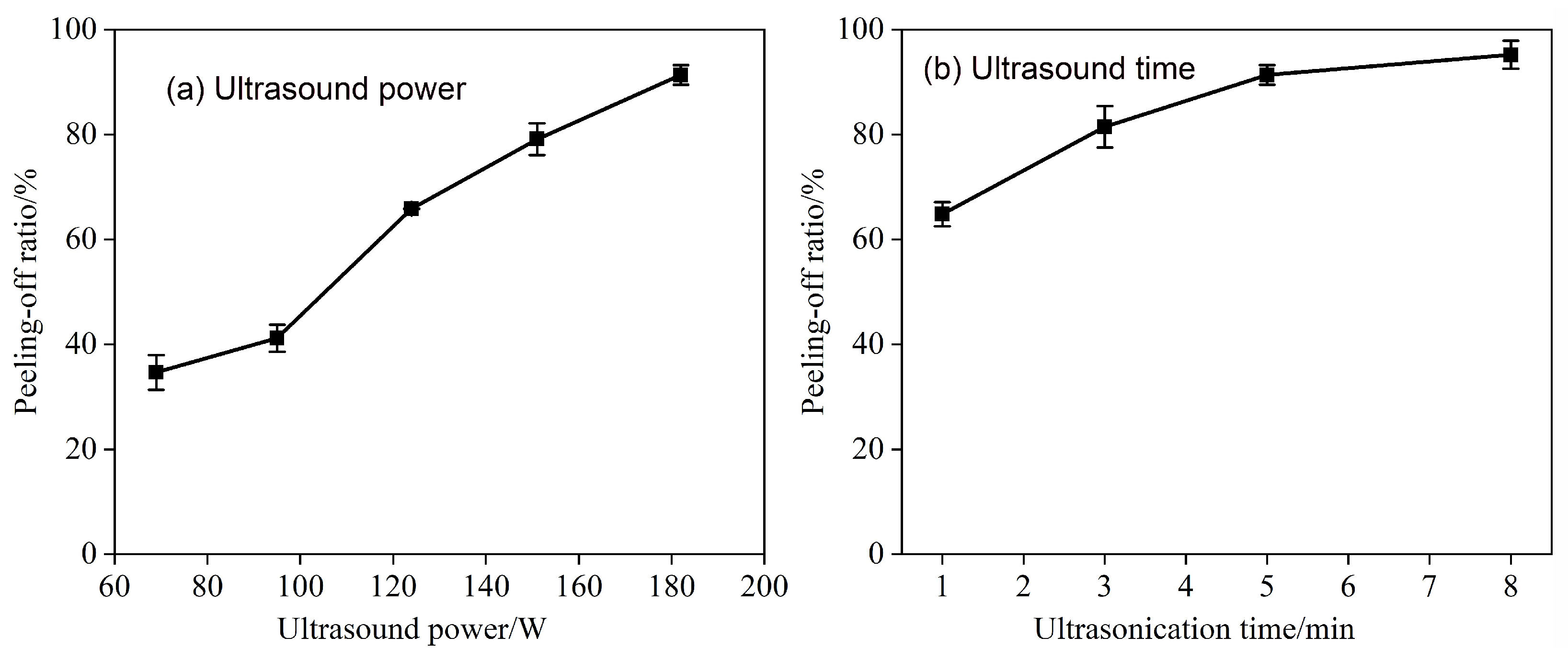
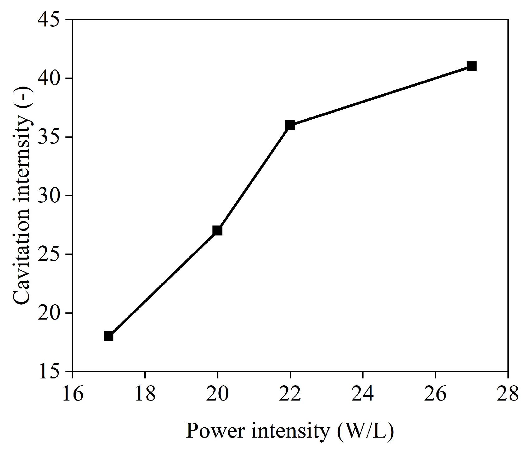
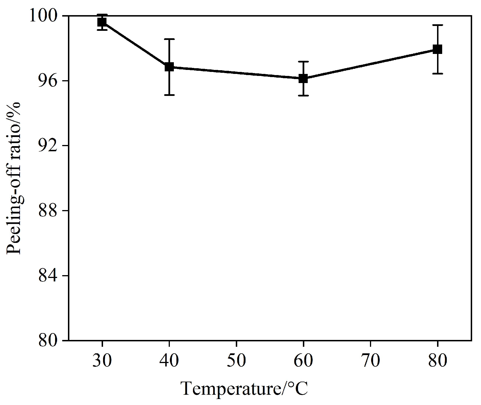
3.2. Ultrasound Treatment

Ultrasound treatment was independently used to further enhance the peeling-off ratio. Figure 5 illustrates the effects of ultrasonication power and time on the ratio. As shown, an increase in ultrasound power led to a significant increase in the ratio from ~35% to ~91% (Figure 5a). Moreover, the ratio was further increased to ~95% with an increase in ultrasonication time from 5 min to 8 min (Figure 5b).
The ultrasound-assisted treatment produced a significantly higher peeling-off performance (~95%) compared to the mechanical agitation treatment (~86%). The increase in the peeling-off ratio was attributed to the increase in the frequency of ultrasound cavitation events. The greater ultrasound input power can decrease the threshold of transient cavitation, leading to an increase in the number of collapsed bubbles and faster microjets [33]. Experimental results in Figure 6 demonstrate that the measured cavitation intensity increased with the increase in ultrasound power intensity [46].
Acoustic cavitation can produce both isotropic and anisotropic bubble collapse, resulting in shock waves and microjets (Figure 7). Compared to the mechanical agitation, ultrasound-induced transient cavitation (bubble collapse) can generate microjets with a speed of around 110 m/s, along with a strong impact force, resulting in a collision density as high as 1.5 kg/cm2, local high temperature (1000 s of Kelvin) and high pressure (100 s of atmospheres) [18]. Moreover, the generated radicals can also act as oxidants to promote the liberation process. Similar enhancement phenomena have been observed in the ultrasound-assisted liberation of cathode materials from Al foils [10,26,27,28,29]. In aqueous reactions, the formation of free radicals in an acoustic field is described as follows [47]:
H 2 O H + + O H
H + + H + H 2
O H + O H H 2 O 2
H + + O H H 2 O
The free radicals generated during the acoustic cavitation can decompose the organic binders present between the graphite electrode material and the Cu foil. The number of generated radicals is controlled by the temperature inside the collapsing bubbles, which can be increased by enhancing sonication power, exceeding external pressure, and reducing external (solution) temperature. This can lead to the creation of more radicals and further promote the liberation process [48].
Figure 7. Diagram of (a) shock wave and (b) microjet generated by cavitation bubble collapse. Remodified from Kim et al. [49].
Separations 10 00246 g007

3.3. Ultrasound-Assisted Treatment Coupled with Mechanical Stirrer

The combination of ultrasound and mechanical agitation (referred to as ultrasound-mechanical stirrer) tests were performed with an ultrasound power of 182 W and mechanical impeller speed of 2000 r/min. Figure 8 shows the effect of treatment time on peeling-off ratio for the ultrasound-assisted treatment coupled with mechanical stirrer. Under different treatment times, the peeling-off ratio for the ultrasound-mechanical stirrer was significantly increased compared to ultrasound and mechanical stirring treatment alone (Figure 8). With the increase in the treatment time from 1 min to 8 min, the peeling-off ratio of ultrasound-mechanical stirrer increased from ~87% to ~98%. The ultrasound-mechanical stirrer was able to produce a relatively high peeling-off ratio in a short time of 1 min, which is attributed to the synergistic effect of mechanical agitation convection and acoustic cavitation phenomena.
The results presented in Figure 9 indicate that the peeling-off rate of the ultrasound-mechanical stirrer was highly dependent on the stirring speed. At a lower stirring speed of 400 rpm, the peeling-off rate was significantly improved by the presence of ultrasound (~100%) compared to that of mechanical stirring alone (~43%). This improvement can be attributed to the physical and chemical effects induced by ultrasonic cavitation. Figure 10 shows the effect of temperature on the peeling-off rate of the ultrasound-mechanical stirrer. It was observed that high-efficient separation can be achieved at a low temperature of 30 °C. However, with an increase in the temperature, there was a slight decrease in the peeling-off rate. This decrease can be attributed to the deterioration of the cavitation intensity at a relatively high temperature, which can be attributed to the changes in saturated vapor pressure, viscosity, and gas content [33,48,50].
The combination of ultrasound and mechanical stirring provides a synergistic effect that enhances the peeling-off rate of graphite electrode material from copper foil. The microjet generated by ultrasound, the local high-temperature and high-pressure environment, and the generated free radicals promote the separation of the graphite electrode material and copper foil at the micro-scale level. Mechanical stirring improves the convection intensity of the fluid in the conical flask, facilitating the rapid transfer of the peeled-off graphite electrode material from the surface of the copper foil. This allows the remaining graphite electrode material that is closely bonded with the copper foil to be fully exposed to the ultrasonic field, further improving the peeling efficiency. The combined effects of ultrasound and mechanical stirring result in a peeling-off rate of approximately 100% for the ultrasound-mechanical stirrer.

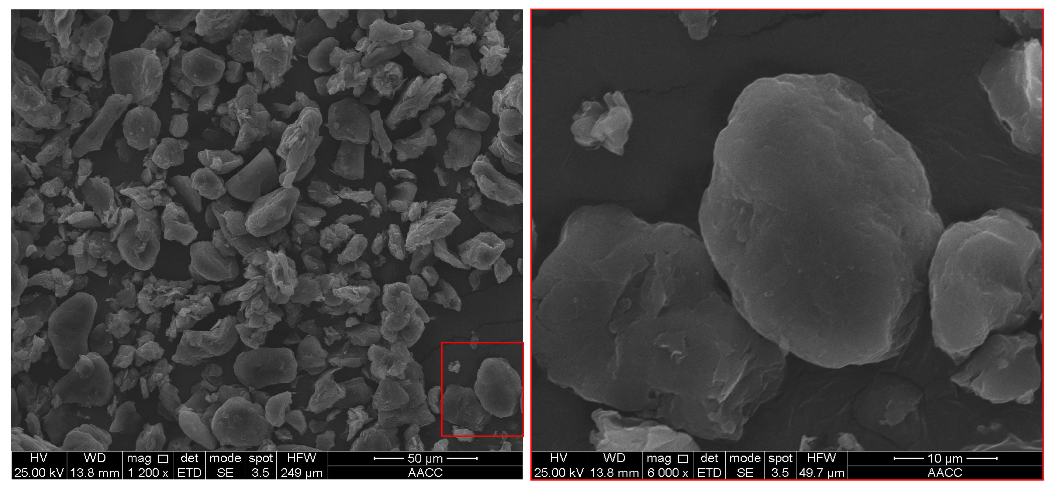
3.4. XRD, XRF, and SEM Analysis of Liberated Graphite Electrode Material

Figure 11 presents the comparative XRD patterns for the fresh graphite material in its pristine state and the spent LIB graphite material liberated from Cu foil. The XRD pattern of the fresh graphite material is taken from the literature [51]. The XRD analysis showed high-intensity peaks near 26.5, consistent with the XRD pattern of standard graphite (Figure 11). This peak corresponds to the diffraction peak of the crystal plane of graphite 002, indicating that the graphite material exhibits typical graphite characteristics and good crystallinity [51,52]. The absence of the stray peaks further proved the purity of the graphite electrode material liberated from Cu foil.
The Bragg equation was used to calculate the interlayer spacing (d002) [52]:
2 d 002 s i n θ = λ
The wavelength (λ) by Cu Kα radiation was 0.15418 nm. The diffraction angles (θ) of the 002 peaks for pristine state and spent LIB graphite electrode materials in Figure 11. were 26.5770° and 26.4991°, respectively. The calculated interlayer spacing (d002) for pristine state and spent LIB graphite electrode materials were 0.3351 nm and 0.3361 nm, respectively. The conclusion can be drawn that the interlayer spacing (002) of the spent LIB graphite electrode material increased compared to the pristine state. This increase in interlayer spacing can be attributed to the transport behavior of lithium ions between the carbon layers of the graphite electrode during the charging and discharging process of LIBs [41,53].
Meanwhile, the XRF results presented in Table 1 show that the graphite electrode material had a high carbon content (C) of 99.85%. Additionally, the SEM images of the liberated graphite electrode material (Figure 12) showed that the particles were smaller than 50 μm, which is consistent with the particle size reported by Nazari et al. [51] for pristine graphite material (with an average size (d90) of 36 μm). Therefore, it can be inferred that the ultrasound-mechanical stirrer effectively dispersed the graphite particles.
The EDS measurement was coupled with SEM to evaluate the possibility of Cu foil contamination on the liberated graphite electrode material. Figure 13 presents the SEM-EDS result of the liberated graphite electrode material. As shown in Figure 13, oxygen element (15.07 Wt.%) was mostly distributed in the conductive substrate comparted to the graphite particle surface, indicating that the graphite material did not contain oxygen element. Although there was a trace of Cu on the surface of graphite material particles, the signal of the Cu element was also detected on the conductive substrate. Therefore, it was concluded that the liberated graphite electrode material had good purity with no significant contamination from the Cu foil.

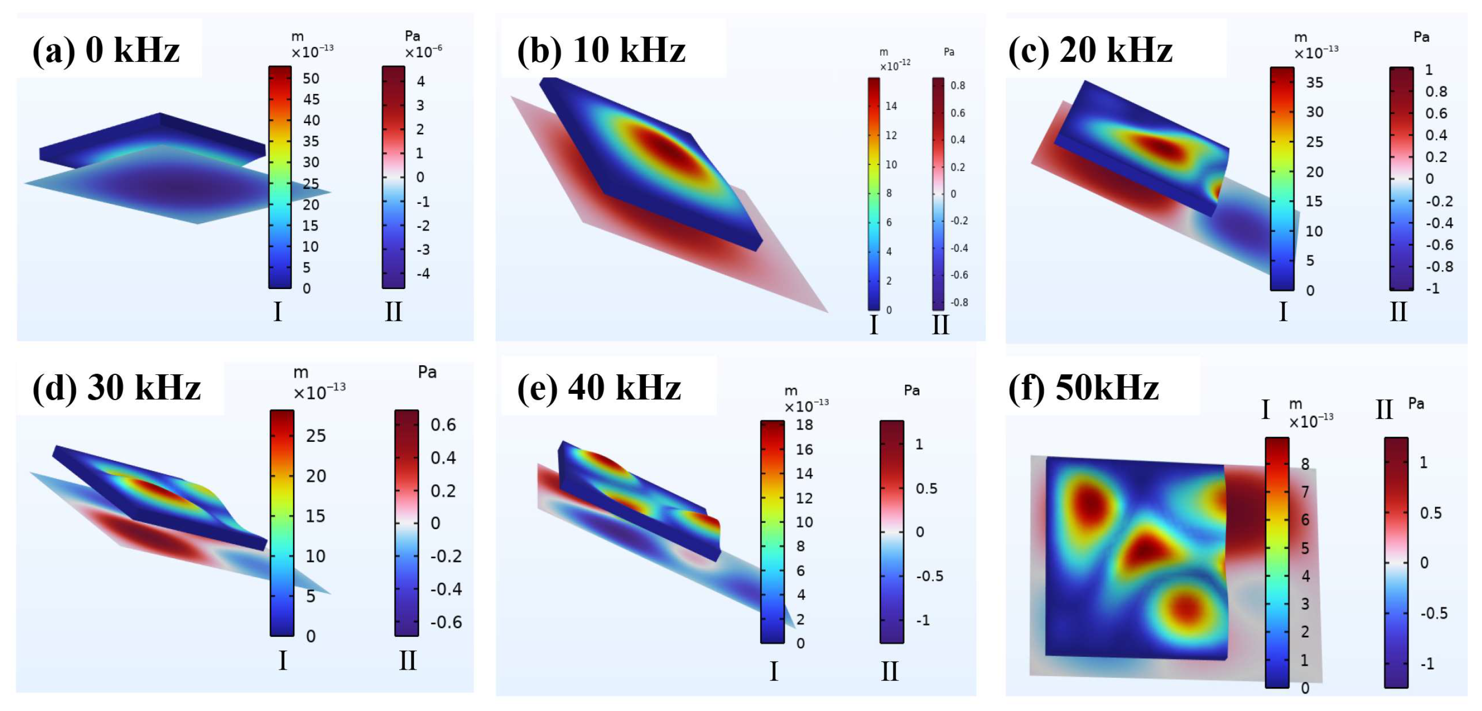
3.5. Numerical Simulation

Numerical simulation analyses revealed that the main effective factor in the separation of graphite from copper anode foil under ultrasonic-assisted delamination was the difference between pressure and ultrasonic temperature changes in the boundary between different anode layers (graphite on copper foil in aqueous solution), as shown in Figure 14. Although the pattern of stress and pressure changes varied in the directions of particles near the ultrasonic source, the analysis still showed structural changes in the boundary of the anode layers due to the different properties of attached layers of copper and graphite, which appeared to be the main reason for the increase in graphite separation from the anode. Therefore, in addition to facilitating mass transfer, stirring can have a significant effect on increasing stresses and intermittent ultrasonic pressures in different directions, thus increasing the time and efficiency of separation of graphite from the copper surface.
Figure 15 shows the graphical analysis of displacement changes caused by compressive stresses from ultrasonic irradiation for different directions of the anode-layered segments compared to the radiation source. The figure highlights the importance of mixing and ultrasonic synchronicity in achieving efficient graphite separation. Changes in the direction and magnitude of compressive stresses and displacements caused by varying the angle of different layers of the anode electrode (copper-graphite) relative to the ultrasonic source can improve graphite separation efficiency. This directional change can be achieved through appropriate mixing and stirring. In addition, the figure shows that, without ultrasonic irradiation, the compressive stress and strain are negligible. However, as the frequency of ultrasonic irradiation increases, the density of stress and resulting strain distribution also increase, which can enhance the time and efficiency of separation.

4. Conclusions

Overall, the study investigated the peeling-off ratio of graphite anode material from Cu foils using mechanical stirring and ultrasound treatments, as well as the combined effects of these processes. XRD, XRF, and SEM-EDS were used to characterize the liberated graphite anode material, which demonstrated good purity. Numerical simulations were used to understand the mechanisms behind ultrasonic and agitation-mediated delamination of anode electrode layers. The results showed that the use of agitated stirring along with low-frequency and energy ultrasonic (40 kHz, 50 W) can provide near-complete recycling (more than 98% graphite recovery) of these valuable materials. The study suggests that combining ultrasonic and mixing agitation can lead to an inexpensive and scalable high-volume method for recycling added value from discarded lithium-ion batteries. Future work will include further studies on the details of the simulation method.

Author Contributions

X.R.: Investigation, Software, Formal analysis, Writing–original draft; Z.T.: Investigation, Software; Y.D.: Investigation, Methodology; G.M.: Investigation, Formal analysis; Z.L.: Investigation, Formal analysis; X.B.: Conceptualization, Software, Writing–original draft, Funding acquisition; M.B.: Formal analysis, Writing–original draft, Writing–review and editing; A.B.V.: Investigation, Formal analysis, Software, Writing –original draft; A.H.: Writing–original draft, Writing–review and editing. All authors have read and agreed to the published version of the manuscript.

Funding

The authors gratefully acknowledge the financial support from the National Natural Science Foundation of China (Grant No. 52204296). In addition, the authors very much appreciate the support by the Undergraduate Training Program for Innovation and Entrepreneurship, China University of Mining and Technology, Xuzhou, China (Grant No. 202210290180Y).

Informed Consent Statement

Not applicable.

Data Availability Statement

Data will be shared upon request.

Acknowledgments

The authors acknowledge the contribution to the manuscript from Xinnan Hu, Chao Ni, and Guangyuan Xie.

Conflicts of Interest

The authors declare no conflict of interest.

References

  1. Lv, W.; Wang, Z.; Cao, H.; Sun, Y.; Zhang, Y.; Sun, Z. A critical review and analysis on the recycling of spent lithium-ion batteries. Acs. Sustain. Chem. Eng. 2018, 6, 1504–1521. [Google Scholar] [CrossRef]
  2. Xu, J.; Thomas, H.R.; Francis, R.W.; Lum, K.R.; Wang, J.; Liang, B. A review of processes and technologies for the recycling of lithium-ion secondary batteries. J. Power Sources 2008, 177, 512–527. [Google Scholar] [CrossRef]
  3. Liu, G.; Wang, N.; Qi, F.; Lu, X.; Liang, Y.; Sun, Z. Novel Ni–Ge–P anodes for lithium-ion batteries with enhanced reversibility and reduced redox potential. Inorg. Chem. Front. 2023, 10, 699–711. [Google Scholar] [CrossRef]
  4. Yu, J.; Lin, M.; Tan, Q.; Li, J. High-value utilization of graphite electrodes in spent lithium-ion batteries: From 3D waste graphite to 2D graphene oxide. J. Hazard Mater. 2021, 401, 123715. [Google Scholar] [CrossRef]
  5. Ke, X.; Liang, Y.; Ou, L.; Liu, H.; Chen, Y.; Wu, W.; Cheng, Y.; Guo, Z.; Lai, Y.; Liu, P.; et al. Surface engineering of commercial Ni foams for stable Li metal anodes. Energy Storage Mater. 2019, 23, 547–555. [Google Scholar] [CrossRef]
  6. Kim, S.; Bang, J.; Yoo, J.; Shin, Y.; Bae, J.; Jeong, J.; Kim, K.; Dong, P.; Kwon, K. A comprehensive review on the pretreatment process in lithium-ion battery recycling. J. Clean Prod. 2021, 294, 126329. [Google Scholar] [CrossRef]
  7. He, Y.; Yuan, X.; Zhang, G.; Wang, H.; Zhang, T.; Xie, W.; Li, L. A critical review of current technologies for the liberation of electrode materials from foils in the recycling process of spent lithium-ion batteries. Sci. Total Environ. 2021, 766, 142382. [Google Scholar] [CrossRef]
  8. Zhang, T.; He, Y.; Ge, L.; Fu, R.; Zhang, X.; Huang, Y. Characteristics of wet and dry crushing methods in the recycling process of spent lithium-ion batteries. J Power Sources 2013, 240, 766–771. [Google Scholar] [CrossRef]
  9. Zhu, S.; He, W. Removal of organic impurities in lithium cobalt oxide from spent lithium ion batteries by ultrasonic irradiation. Adv. Mater. Res. 2014, 864–867, 1937–1940. [Google Scholar] [CrossRef]
  10. Yan, S.; Jiang, Y.; Chen, X.; Zhou, T. Improved advanced oxidation process for in situ recycling of al foils and cathode materials from spent lithium-ion batteries. Ind. Eng. Chem. Res. 2022, 61, 12728–12738. [Google Scholar] [CrossRef]
  11. Zhang, Y.L.; Li, X.D.; Chen, X.P.; Koivula, R.; Xu, J.H. Tunnel manganese oxides prepared using recovered LiMn2O4 from spent lithium-ion batteries: Co adsorption behavior and mechanism. J. Hazard Mater. 2022, 425, 127957. [Google Scholar] [CrossRef]
  12. He, L.; Sun, S.; Song, X.; Yu, J. Recovery of cathode materials and Al from spent lithium-ion batteries by ultrasonic cleaning. Waste Manag. 2015, 46, 523–528. [Google Scholar] [CrossRef]
  13. Yang, L.; Xi, G.; Xi, Y. Recovery of Co, Mn, Ni, and Li from spent lithium ion batteries for the preparation of LiNixCoyMnzO2 cathode materials. Ceram Int. 2015, 41, 11498–11503. [Google Scholar] [CrossRef]
  14. Li, L.; Lu, J.; Ren, Y.; Zhang, X.X.; Chen, R.J.; Wu, F.; Amine, K. Ascorbic-acid-assisted recovery of cobalt and lithium from spent Li-ion batteries. J. Power Sources 2012, 218, 21–27. [Google Scholar] [CrossRef]
  15. Wang, M.; Tan, Q.; Liu, L.; Li, J. A low-toxicity and high-efficiency deep eutectic solvent for the separation of aluminum foil and cathode materials from spent lithium-ion batteries. J. Hazard Mater. 2019, 380, 120846. [Google Scholar] [CrossRef] [PubMed]
  16. Zhang, G.; He, Y.; Feng, Y.; Wang, H.; Zhu, X. Pyrolysis-ultrasonic-assisted flotation technology for recovering graphite and licoo2 from spent lithium-ion batteries. ACS Sustain. Chem. Eng. 2018, 6, 10896–10904. [Google Scholar] [CrossRef]
  17. Li, J.; Shi, P.; Wang, Z.; Chen, Y.; Chang, C. A combined recovery process of metals in spent lithium-ion batteries. Chemosphere 2009, 77, 1132–1136. [Google Scholar] [CrossRef]
  18. Bu, X.; Danstan, J.K.; Hassanzadeh, A.; Vakylabad, A.B.; Chelgani, S.C. Metal extraction from ores and waste materials by ultrasound-assisted leaching—An overview. Min. Proc. Ext. Met. Rev. 2022, 1–18. [Google Scholar] [CrossRef]
  19. Vyas, S.; Ting, Y. Review of the application of ultrasound in bioleaching and insights from sonication in (bio)chemical processes. Resources 2018, 7, 3. [Google Scholar] [CrossRef] [Green Version]
  20. Ritesh, P.; Srivastava, V.C. Understanding of ultrasound enhanced electrochemical oxidation of persistent organic pollutants. J. Water Process Eng. 2020, 37, 101378. [Google Scholar] [CrossRef]
  21. Babu, S.G.; Ashokkumar, M.; Neppolian, B. The role of ultrasound on advanced oxidation processes. Topics Curr. Chem. 2016, 374, 75. [Google Scholar] [CrossRef] [PubMed]
  22. Zhou, M.; Liu, K.; Wei, M.; Zhang, J.; Chen, S.; Cheng, W. Recovery of lithium iron phosphate by specific ultrasonic cavitation parameters. Sustainability 2022, 14, 3390. [Google Scholar] [CrossRef]
  23. Toma, C.M.; Ghica, G.V.; Buzatu, M.; Petrescu, M.I.; Vasile, E.; Iacob, G. A recovery process of active cathode paste from spent li-ion batteries. In Proceedings of the International Conference on Innovative Research—ICIR Euroinvent 2017, Iasi, Romania, 25–26 May 2017; Sandu, A.V., Abdullah, M., Vizureanu, P., Ghazali, C., Sandu, I., Eds.; [Google Scholar]
  24. Chen, X.; Li, S.; Wu, X.; Zhou, T.; Ma, H. In-situ recycling of coating materials and Al foils from spent lithium ion batteries by ultrasonic-assisted acid scrubbing. J. Clean Prod. 2020, 258, 120943. [Google Scholar] [CrossRef]
  25. Bian, D.; Sun, Y.; Li, S.; Tian, Y.; Yang, Z.; Fan, X.; Zhang, W. A novel process to recycle spent LiFePO4 for synthesizing LiFePO4/C hierarchical microflowers. Electrochim. ACTA 2016, 190, 134–140. [Google Scholar] [CrossRef]
  26. Yan, S.X.; Sun, C.H.; Zhou, T.; Gao, R.C.; Xie, H.S. Ultrasonic-assisted leaching of valuable metals from spent lithium-ion batteries using organic additives. Sep. Purif. Technol. 2021, 257, 117930. [Google Scholar] [CrossRef]
  27. Zhao, S.; Zhang, W.; Li, G.; Zhu, H.; Huang, J.; He, W. Ultrasonic renovation mechanism of spent LCO batteries: A mild condition for cathode materials recycling. Resour. Conserv. Recycl. 2020, 162, 105019. [Google Scholar] [CrossRef]
  28. Zhao, S.; Zhang, W.; Li, G.; Zhu, H.; Huang, J.; He, W. Ultrasonic renovating and coating modifying spent lithium cobalt oxide from the cathode for the recovery and sustainable utilization of lithium-ion battery. J. Clean Prod. 2020, 257, 120510. [Google Scholar] [CrossRef]
  29. Huang, T.; Zhang, S.W.; Zhou, L.L.; Tao, H.; Li, A.Y. Synergistic effect of ultrasonication and sulfate radical on recovering cobalt and lithium from the spent lithium-ion battery. J. Environ. Manag. 2022, 305, 114395. [Google Scholar] [CrossRef] [PubMed]
  30. Cheng, Q.; Marchetti, B.; Chen, X.; Xu, S.; Zhou, X. Separation, purification, regeneration and utilization of graphite recovered from spent lithium-ion batteries—A review. J. Environ. Chem. Eng. 2022, 10, 107312. [Google Scholar] [CrossRef]
  31. Natarajan, S.; Boricha, A.B.; Bajaj, H.C. Recovery of value-added products from cathode and anode material of spent lithium-ion batteries. Waste Manag. 2018, 77, 455–465. [Google Scholar] [CrossRef]
  32. Yasui, K. Unsolved problems in acoustic cavitation. In handbook of ultrasonics and sonochemistry. In Handbook of Ultrasonics and Sonochemistry; Ashokkumar, M., Cavalieri, F., Chemat, F., Okitsu, K., Sambandam, A., Yasui, K., Zisu, B., Eds.; Springer: Singapore, 2016; pp. 1–34. [Google Scholar]
  33. Yasui, K. Acoustic Cavitation and Bubble Dynamics; Springer International Publishing: Cham, Switzerland, 2018. [Google Scholar]
  34. Ferrero, F.; Periolatto, M. Ultrasound for low temperature dyeing of wool with acid dye. Ultrason. Sonochem. 2012, 19, 601–606. [Google Scholar] [CrossRef] [PubMed]
  35. Zhang, M.; Yewe-Siang, M.; Lee Shee, W.; Wu, H. Direct emulsification of crude glycerol and bio-oil without addition of surfactant via ultrasound and mechanical agitation. Fuel 2018, 227, 183–189. [Google Scholar] [CrossRef]
  36. Elhag, H.E.E.A.; Naila, A.; Nour, A.H.; Ajit, A.; Sulaiman, A.Z.; Aziz, B.A. Optimization of protein yields by ultrasound assisted extraction from Eurycoma longifolia roots and effect of agitation speed. J. King Saud Univ.—Sci. 2019, 31, 913–930. [Google Scholar] [CrossRef]
  37. Lee, C.; Hun, L.; Yaakob, H.; Luing, W.S.; Jannet, H.B. Optimization of ultrasound-assisted extraction of total flavonoids content from the white flowering variety of Melastoma Malabathricum. J. Kejuruter. SI 2019, 2, 91–102. [Google Scholar] [CrossRef]
  38. Chemat, F.; Rombaut, N.; Sicaire, A.; Meullemiestre, A.; Fabiano-Tixier, A.; Abert-Vian, M. Ultrasound assisted extraction of food and natural products. Mechanisms, techniques, combinations, protocols and applications. A review. Ultrason. Sonochem. 2017, 34, 540–560. [Google Scholar] [CrossRef] [PubMed]
  39. Lupatini, A.L.; de Oliveira Bispo, L.; Colla, L.M.; Costa, J.A.V.; Canan, C.; Colla, E. Protein and carbohydrate extraction from S. platensis biomass by ultrasound and mechanical agitation. Food Res. Int. 2017, 99, 1028–1035. [Google Scholar] [CrossRef] [PubMed]
  40. Nie, G.; Hu, K.; Ren, W.; Zhou, P.; Duan, X.; Xiao, L.; Wang, S. Mechanical agitation accelerated ultrasonication for wastewater treatment: Sustainable production of hydroxyl radicals. Water Res. 2021, 198, 117124. [Google Scholar] [CrossRef]
  41. Abdollahifar, M.; Doose, S.; Cavers, H.; Kwade, A. Graphite recycling from end-of-life lithium-ion batteries: Processes and applications. Adv. Mater. Technol. 2022, 8, 2200368. [Google Scholar] [CrossRef]
  42. Natarajan, S.; Aravindan, V. An urgent call to spent lib recycling: Whys and wherefores for graphite recovery. Adv. Energy Mater. 2020, 10, 2002238. [Google Scholar] [CrossRef]
  43. Wang, X.; Bu, X.; Ni, C.; Zhou, S.; Yang, X.; Zhang, J.; Alheshibri, M.; Peng, Y.; Xie, G. Effect of scrubbing medium’s particle size on scrubbing flotation performance and mineralogical characteristics of microcrystalline graphite. Miner Eng. 2021, 163, 106766. [Google Scholar] [CrossRef]
  44. Bu, X.; Evans, G.; Xie, G.; Peng, Y.; Zhang, Z.; Ni, C.; Ge, L. Removal of fine quartz from coal-series kaolin by flotation. Appl. Clay Sci. 2017, 143, 437–444. [Google Scholar] [CrossRef]
  45. Tailleux, R.; Rouleau, L. The effect of mechanical stirring on horizontal convection. Tellus A 2010, 62, 138–153. [Google Scholar] [CrossRef] [Green Version]
  46. Niemczewski, B. Cavitation intensity of water under practical ultrasonic cleaning conditions. Ultrason. Sonochem. 2014, 21, 354–359. [Google Scholar] [CrossRef] [PubMed]
  47. Thompson, L.H.; Doraiswamy, L.K. Sonochemistry: Science and Engineering. Ind. Eng. Chem. Res. 1999, 38, 1215–1249. [Google Scholar] [CrossRef]
  48. Kentish, S.; Ashokkumar, M. The Physical and Chemical Effects of Ultrasound; Feng, H., Barbosa-Canovas, G., Weiss, J., Eds.; Springer: New York, NY, USA, 2011; pp. 1–12. [Google Scholar]
  49. Kim, Y.C.; Min, H.; Yu, J.; Hong, S.Y.; Wang, M.; Kim, S.H.; Suhr, J.; Lee, Y.K.; Kim, K.J.; Nam, J. Forced infiltration of silica beads into densely-packed glass fibre beds for thin composite laminates. RSC Adv. 2016, 6, 91341–91348. [Google Scholar]
  50. Xu, H.; Tu, J.; Niu, F.; Yang, P. Cavitation dose in an ultrasonic cleaner and its dependence on experimental parameters. Appl. Acoust. 2016, 101, 179–184. [Google Scholar] [CrossRef]
  51. Nazari, S.; Zhou, S.; Hassanzadeh, A.; Li, J.; He, Y.; Bu, X.; Kowalczuk, P.B. Influence of operating parameters on nanobubble-assisted flotation of graphite. J. Mater. Res. Technol. 2022, 20, 3891–3904. [Google Scholar] [CrossRef]
  52. Lee, Y.; Hatori, H. The dependence of B retentivity on carbon crystallinity. Mater. Chem. Phys. 2003, 82, 258–262. [Google Scholar] [CrossRef]
  53. He, K.; Zhang, Z.Y.; Zhang, F.S. Synthesis of graphene and recovery of lithium from lithiated graphite of spent Li-ion battery. Waste Manag. 2021, 124, 283–292. [Google Scholar] [CrossRef]
Figure 1. The schematical diagram of the preparation of the cut Cu electrodes.
Separations 10 00246 g001
Figure 2. Diagram of the peeling-off experimental system of the cut Cu electrodes in (a) a mechanical stirrer, (b) an ultrasonic cleaner, and (c) the combined process of a mechanical stirrer and an ultrasonic cleaner.
Separations 10 00246 g002
Figure 3. A piece of an anode electrode for qualitative simulation purposes.
Separations 10 00246 g003
Figure 4. Effects of mechanical stirring speed ((a) 5-min stirring time), and stirring time ((b) 2000 r/min) on peeling-off ratios of the graphite.
Separations 10 00246 g004
Figure 5. Effects of ultrasound power ((a) 5-min ultrasonication time) ultrasonication time ((b) 182 W ultrasound power) on peeling-off ratios of graphite.
Separations 10 00246 g005
Figure 6. Effect of power intensity on cavitation intensity in a 40 kHz ultrasonic cleaner (25 °C, 15 L water) (modified from [46]).
Separations 10 00246 g006
Figure 8. Effect of treatment time on peeling-off ratio of ultrasound-mechanical stirrer.
Separations 10 00246 g008
Figure 9. Effect of mechanical stirring speed on peeling-off ratio of ultrasound-mechanical stirrer.
Separations 10 00246 g009
Figure 10. Effect of temperature on peeling-off ratio of ultrasound-mechanical stirrer.
Separations 10 00246 g010
Figure 11. Comparisons of the XRD patterns of unused (pristine state) and used graphite electrode materials.
Separations 10 00246 g011
Figure 12. SEM image of the liberated graphite electrode material (the right image is an enlarged image of the red area).
Separations 10 00246 g012
Figure 13. SEM-EDS result of the liberated graphite electrode material.
Separations 10 00246 g013
Figure 14. Numerical simulation of layered copper-graphite anode material at various directions toward ultrasonic irradiation source. Rotation of the surface of chunks of anodic material: (a) with the proximity of graphite to the ultrasonic source, (b) with the proximity of copper to the ultrasonic source.
Separations 10 00246 g014
Figure 15. Increasing the density of displacements and acoustic compressive stresses as a function of increasing the frequency of ultrasonic irradiation (a) 0 kHz (without ultrasonics), (b) 10 kHz, (c) 20 kHz, (d) 30 kHz, (e) 40 kHz, and (f) 50 kHz.
Separations 10 00246 g015
Table 1. XRF analysis of the liberated graphite electrode material (Wt. %).
CCuMoSZrRuFe
99.850.060.0310.0220.0170.0150.005
Disclaimer/Publisher’s Note: The statements, opinions and data contained in all publications are solely those of the individual author(s) and contributor(s) and not of MDPI and/or the editor(s). MDPI and/or the editor(s) disclaim responsibility for any injury to people or property resulting from any ideas, methods, instructions or products referred to in the content.

