Article

Recovery of Carbon and Cryolite from Spent Carbon Anode Slag Using a Grinding Flotation Process Based on Mineralogical Characteristics

1
School of Chemical Engineering and Technology, China University of Mining and Technology, Xuzhou 221116, China
2
Department of Mining Engineering, Shanxi Institute of Technology, Yangquan 045000, China
3
Department of Mining Engineering, Balochistan University of Information Technology, Engineering and Management Sciences (BUITEMS), Quetta 87300, Pakistan
4
Key Laboratory of Coal Processing and Efficient Utilization, China University of Mining and Technology, Ministry of Education, Xuzhou 221116, China
*
Authors to whom correspondence should be addressed.
These authors contributed equally to this work.
Separations 2023, 10(3), 193; https://doi.org/10.3390/separations10030193
Submission received: 20 February 2023 / Revised: 4 March 2023 / Accepted: 10 March 2023 / Published: 12 March 2023

Abstract

:
The aluminum electrolysis industry continually and unavoidably produces hazardous solid waste in the form of carbon anode slag. Carbon anode slag poses a serious environmental pollution risk, and it must be disposed of in a harmless manner. On the other hand, it contains a few valuable resources, as well. In order for the aluminum electrolysis industry to develop in an environmentally friendly and high-quality manner, the harmless disposal of carbon anode slag and its resourceful utilization are of considerable importance. The selective comminution of carbon and cryolite particles in carbon anode slag can be effectively achieved with grinding pretreatment. However, the optimization study of grinding process parameters has yet to be investigated. Therefore, firstly, the mineralogical characteristics and existing mode of carbon anode slag from the perspective of mineralogical properties are analyzed in this study. Then, the effects of grinding time, grinding concentration, and steel ball diameter on the particle size of the ground product (γ−0.074 mm) are investigated using response surface analysis. The results showed that the effect of grinding time was the most significant, followed by grinding concentration and steel ball diameter. In addition, the performance of the multi-stage flotation process for separating the −0.074 mm ground product was analyzed. Cryolite with a purity of 93.12% and a carbon product with an ash content of 10.67% could be simultaneously obtained through multi-stage flotation. It should be pointed out that the deep dissociation and efficient recovery of fine undissociated particles still need to be further explored.

1. Introduction

Aluminum has a variety of uses in the building, transportation, electric power, packaging, national security, and high-tech industries due to its unique chemical and physical properties [1]. Cryolite-alumina molten salt electrolysis is mainly applied in modern industrial aluminum production [2,3]. As the aluminum production process continues, a large amount of carbon anode slag is produced in the electrolytic cell. Carbon slag is an unavoidable solid waste in the electrolytic aluminum industry, which increases energy consumption, induces the anode effect, and so on. Carbon slag is composed of 60–70% electrolyte fraction (Na3AlF6, Al2O3, etc.) and 30–40% carbonaceous material [4]. The carbon anode slag from the electrolytic aluminum production process is classified as toxic hazardous waste by China’s National Hazardous Waste List (2021 Edition) (code: 321-025-48; hazard characteristic: T), so it is strictly prohibited to dispose of or store it in the open [5]. According to the International Aluminum Institute (IAI), the world’s annual primary aluminum production in 2021 was approximately 67,092 thousand metric tons, of which China produced 38,503 thousand metric tons, accounting for 57.39% of the world’s total production [6]. About 5–15 kg of carbon anode slag is generated from 1t of aluminum production [7]. From this, it has been estimated that the world’s primary aluminum production generated 335–1006 thousand tons of carbon anode slag in 2021, of which 193–578 thousand tons were from China. It is essential to use carbon anode slag as a resource due to the enormous amount that is produced each year. The importance of carbon anode slag lies in the recovery of valuable carbon and cryolite as well as the environmentally sound treatment of fluoride.
At present, the treatment methods of carbon anode slag from electrolytic aluminum mainly include flotation [8,9], vacuum smelting [10], physical activation, roasting, alkali fusion, bubbling fluidized bed combustion [4], and co-treatment with other waste slag [11]. The most promising approach for recovering carbon slag for industrial applications among them is flotation, which is an effective method for the separation of fine mineral particles [12] and has the benefits of high processing capacity per unit of time, low cost, and simple operation [4]. Li et al. [8] investigated the effects of particle size, impeller speed, flotation concentration, pH adjuster, and collector addition on the flotation performance of carbon anode slag. They concluded that under the optimal conditions, the carbon purity increased from 23.30% to 75.60%, and the carbon recovery rate was as high as 86.90%. Wang et al. [9] optimized the influencing factors (grinding time, flotation concentration, collector dosage, frother dosage, etc.) of the carbon slag flotation process based on the selectivity index (SI) and analyzed the separation performance of carbon and cryolite in the carbon anode slag. It was found that the SI value under optimal grinding flotation was about four times higher than that under direct flotation. The carbon anode slag possessed better flotation selectivity under the grinding flotation method, which effectively improved the flotation recovery of carbon anode slag. Mei et al. [13] conducted a comparative experiment using a closed-circuit process under the conditions of optimal grinding size, flotation concentration, and impeller speed. The flotation product quality was significantly improved, with an 8.77% reduction in the electrolyte content of the carbon concentrate and a 3.09% reduction in the carbon content of the electrolyte concentrate. According to the studies mentioned above, the carbon anode slag is pulverized before flotation in order to separate the carbon from the cryolite. The performance of grinding is influenced by several variables such as, slurry density, ball diameter, filling rate, feed size distribution, the mode of grinding (wet or dry) [14,15,16].
For carbon anode slag of electrolytic aluminum, Ni et al. [7] investigated the selective comminution and grinding mechanisms of rod and ball mills and proposed that a higher degree of selective comminution of carbon anode slag can be achieved from ball grinding. However, the optimization of grinding process parameters has not been reported. In this paper, the mineralogical characteristics of the carbon anode slag were analyzed first. Based on this, the response surface design method was used to study the effects of grinding time, grinding concentration, and steel ball diameter on the particle size of the ground product. The ground product (−0.074 mm particle size) was then separated using a multi-stage flotation method. The performance of recovering carbon and cryolite from spent carbon anode slag using a combination method of conventional grinding and flotation was discussed from the perspective of mineralogical characteristics.

2. Materials and Methods

2.1. Materials

The carbon anode slag used in this study (ash content of 53.54%) was acquired from an aluminum electrolysis plant in Wenshan, Yunnan Province.

2.2. Methods

2.2.1. Wet Ball-Milling Experiments

An XMQ-Φ240 × 90 laboratory-scale ball mill (Wuhan Exploring Machinery Factory, Wuhan, China), the detailed parameters of which are shown in [17], was used for the milling experiments. The mass of the steel ball (grinding medium) and feed sample was 5.6 kg and 560 g, respectively. The grinding concentration refers to the amount of spent carbon anode slag in the solution, namely the mass percentage concentration. The levels of selected factors are listed in Table 1. The Box–Behnken response surface design method was employed using the Design-Expert V.8.0.6.1 software, and 17 runs, given in Table 2, were obtained and performed.

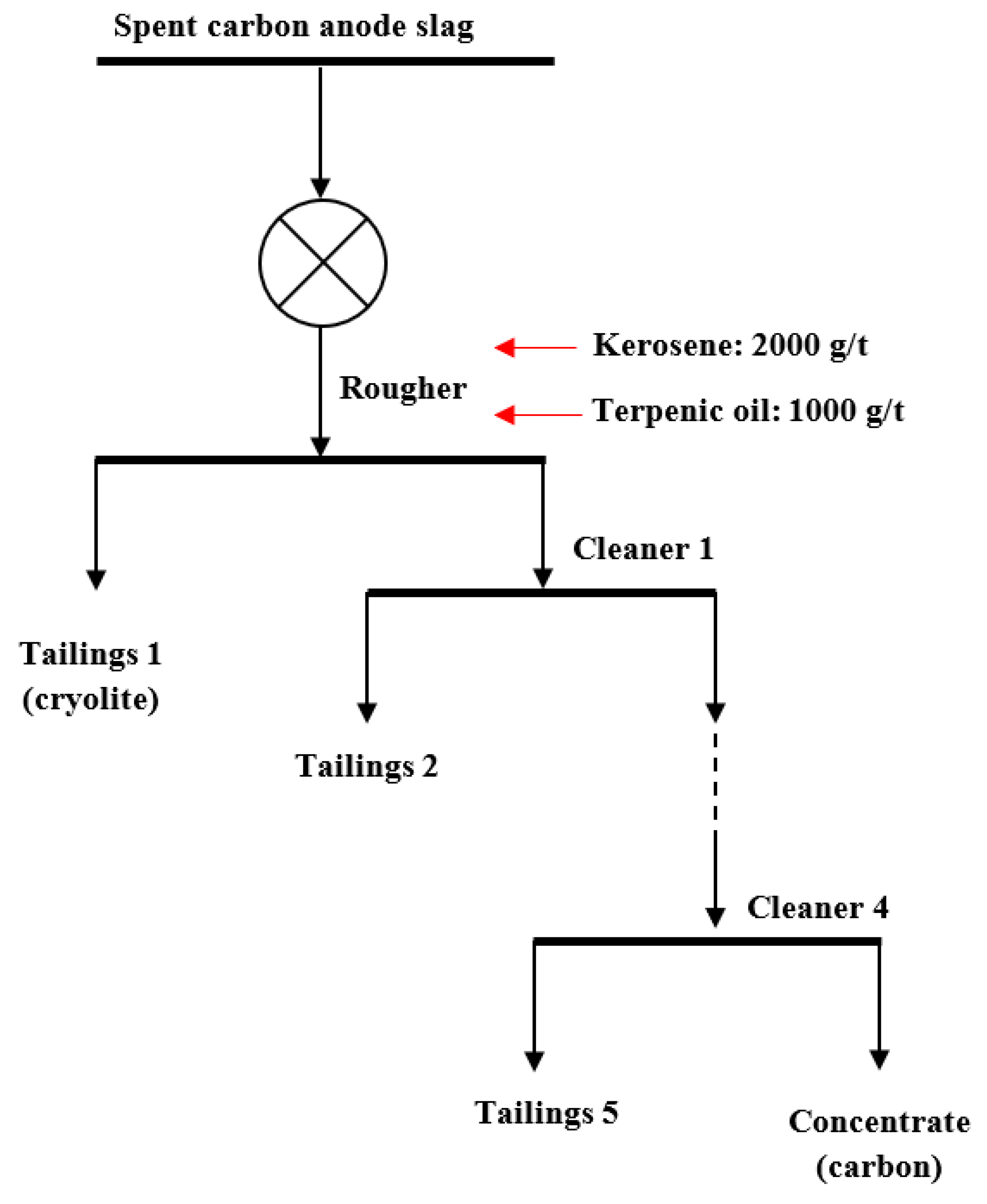
2.2.2. Flotation Tests

The flotation tests were conducted using a 1L RK/FD-II flotation machine (Wuhan Rock Grinding Equipment Manufacturing Co., Ltd., Wuhan, China) with a rotation speed of 1800 r/min, and an aeration volume of 200 L/h. The materials, with particle size of −0.074 mm, were fed into the flotation machine. The flotation concentration was 150 g/L. The dosage of the collector (kerosene) and frother (terpenic oil) were 2000 g/t and 1000 g/t, respectively. The feed materials were pre-wetted for 2 min, and conditioned with a collector and frother for 2 min and 0.5 min, respectively [9]. A multi-stage flotation process was adopted in this study (see Figure 1). The collector and frother were both added in the first stage, and the foam was scraped until no floating materials emerged. In the other stages, only tap water was added to guarantee an appropriate pulp level, and the foam was scraped for 3 min.

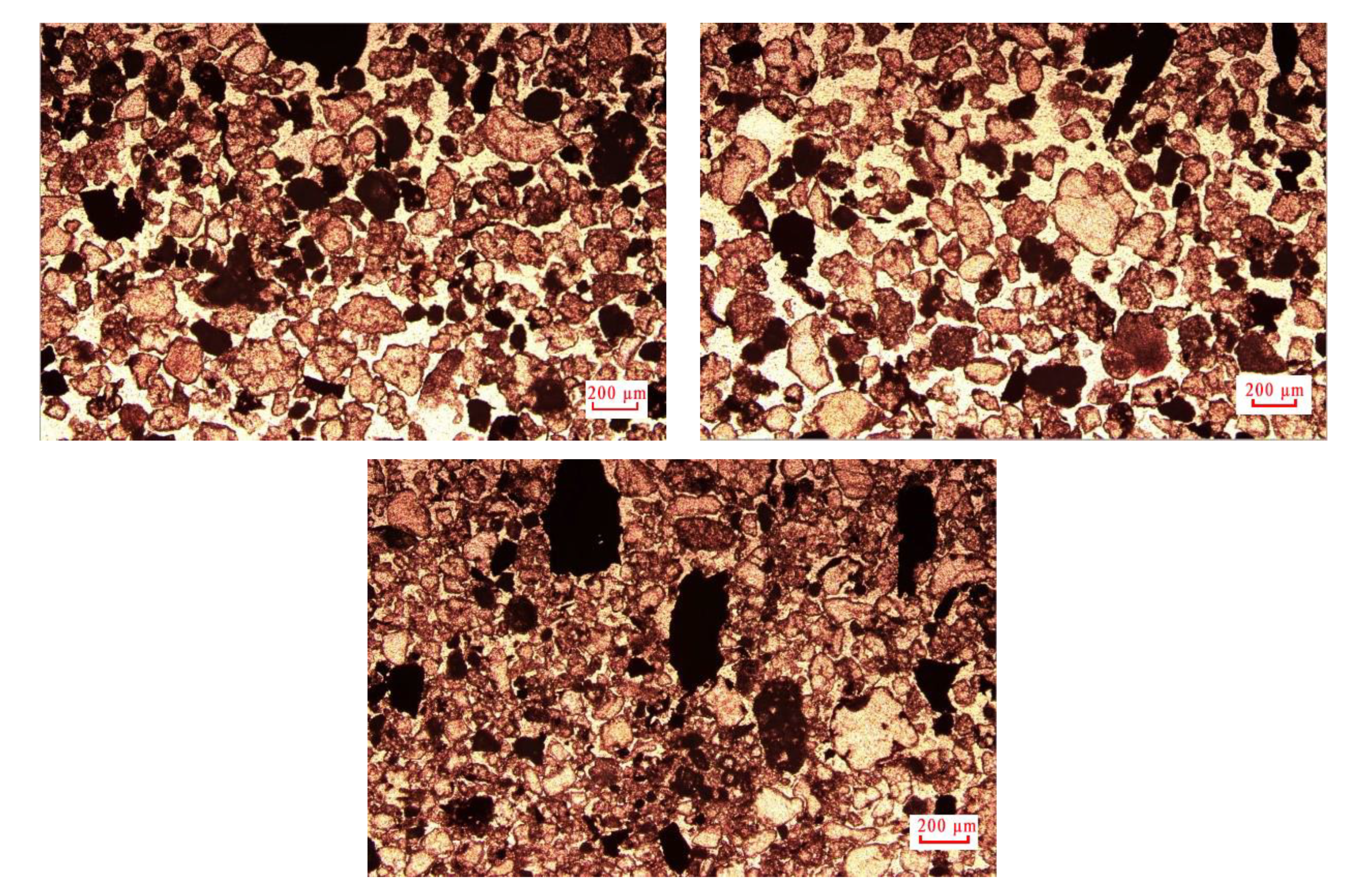
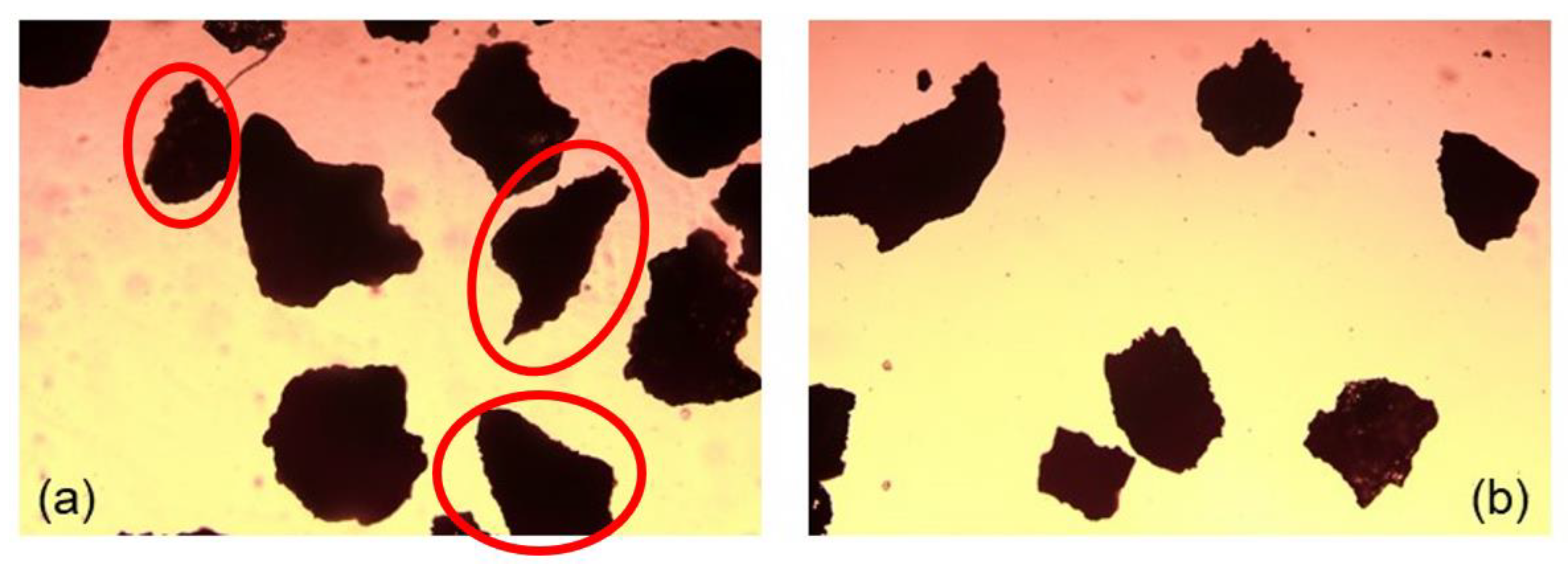
2.2.3. Microscopic Observation

Microscopic observations were carried out using a CX40P series polarizing microscope (Sunny Optical Technology Co. Ltd., Zhejiang, China). For the raw carbon anode slag, a thin section was made by Beijing Riyueshi Mining Technology Development Co., Ltd. (Beijing, China), and then measured with the CX40P microscope. For the particles before and after grinding, the particles were first added to absolute ethanol and then sonicated for five minutes to ensure they were evenly dispersed before and after grinding. The ethanol-containing particles were then pipetted onto the glass slide and observed under a microscope after the ethanol evaporated.

2.2.4. Routine Analysis

The calorific value was measured basing on the national standard GB/T 213-2008 of determination method of calorific value of coal. Mineralogical and chemical characterizations were carried out using X-Ray diffraction (XRD, 6100, Shimadzu Corporation, Kyoto, Japan), X-ray fluorescence (XRF, Zetium, PANalytical B.V, Almelo, The Netherlands), and Scanning Electron Microscopy/Energy Dispersive Spectroscopy (SEM-EDS, FIB-SEM, Helios G4 CX, Thermo Fisher Scientific, Waltham, MA, USA) according to the literature [18]. The particle size distribution of the spent anode carbon slag was obtained by the wet sieving method, while that of the fine particles (the flotation middlings in this study) was measured using a laser particle size analyzer (S3500, Microtrac Inc., Montgomeryville, PA, USA).

3. Results and Discussion

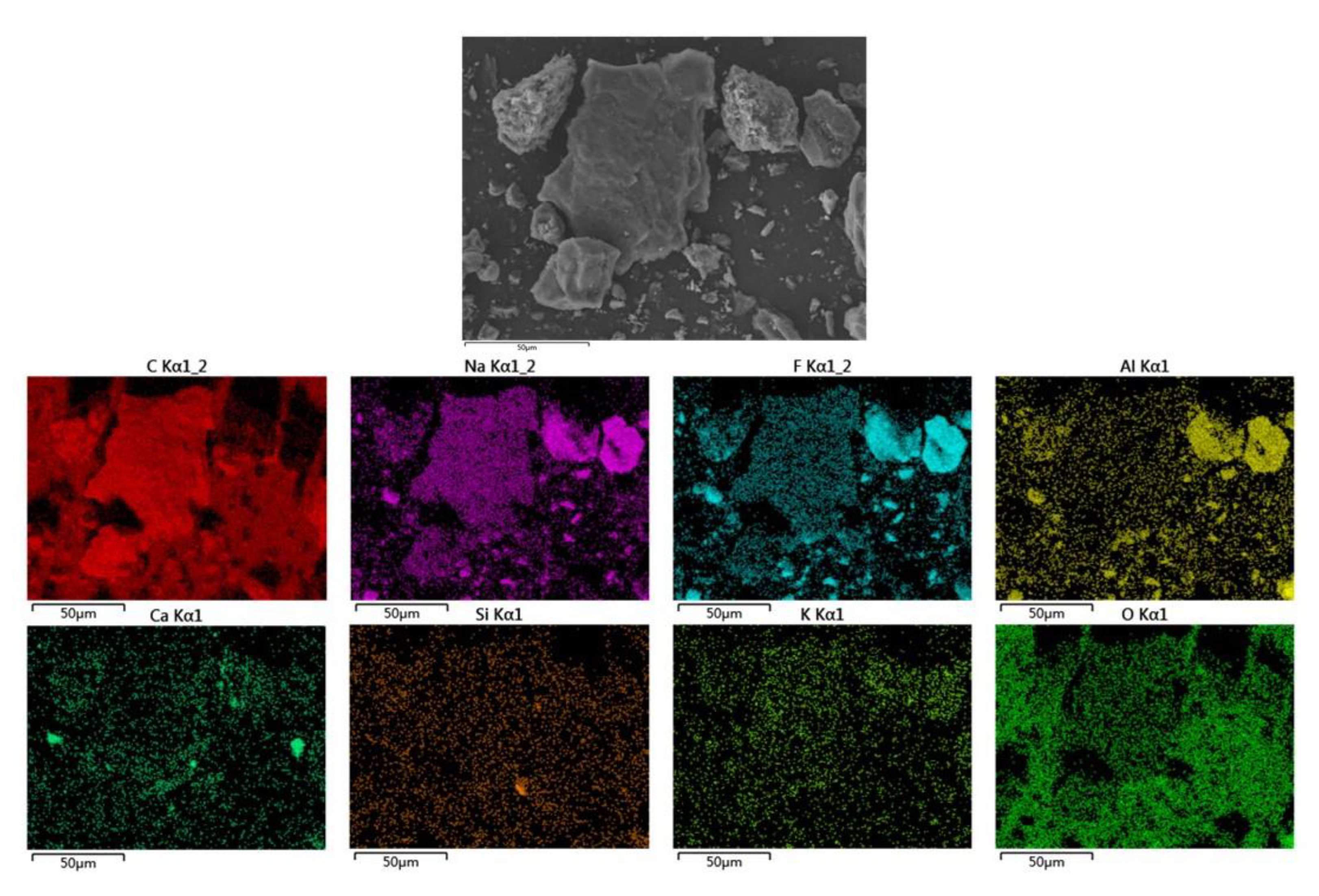
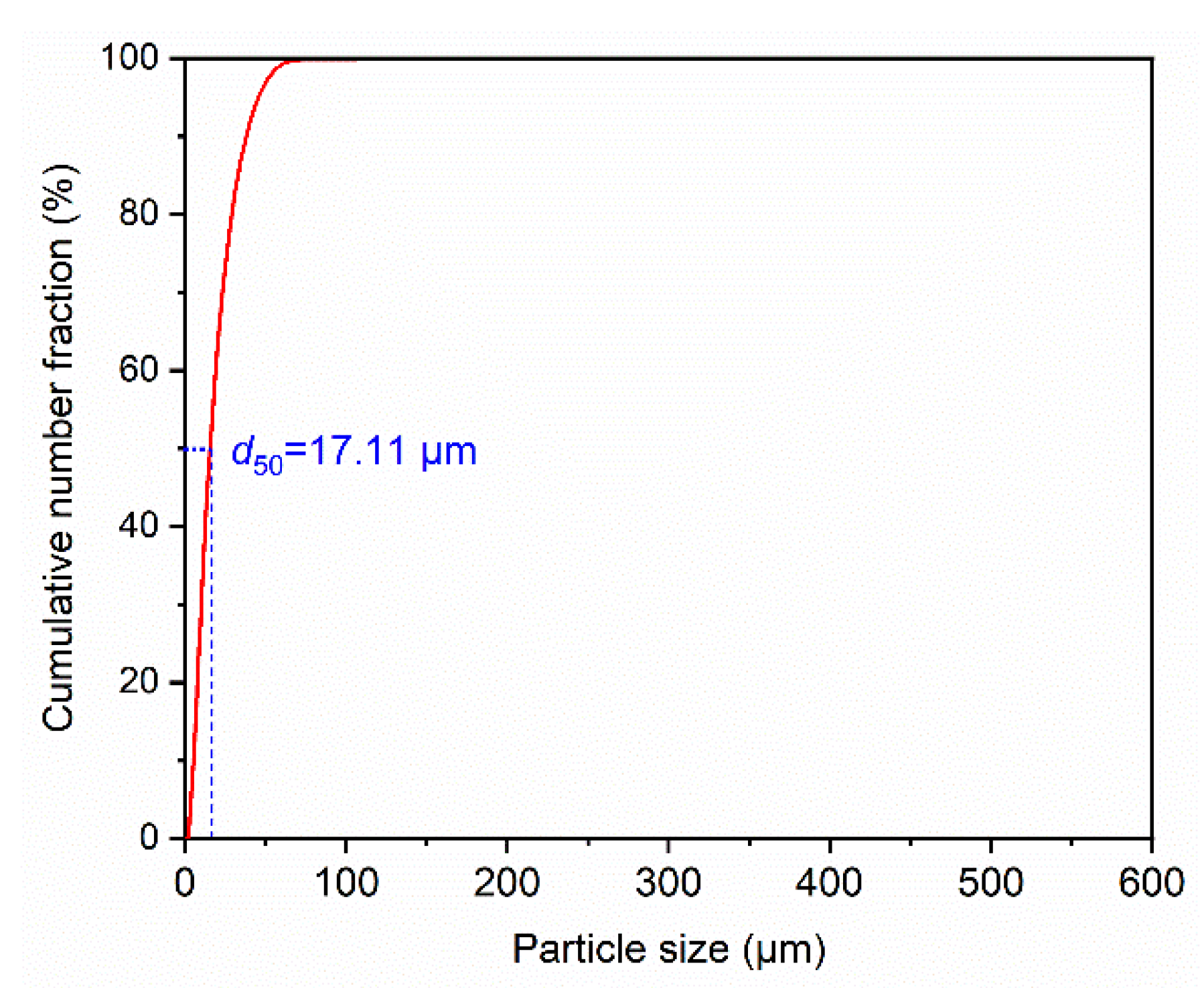
3.1. Mineralogical Characteristics of Spent Carbon Anode Slag

Crushed and sieved spent carbon anode slag was used for the tests with an upper particle size limit of 3 mm. The particle size composition of the spent anode carbon slag is shown in Table 3. A yield of 49.86% was observed for 3–1 mm particles, the ash content of each particle size was between 50% and 60%, and the average particle size (d50) was approximately 1 mm. The XRD and XRF results for the spent carbon anode slag are shown in Figure 2 and Table 4, respectively. Figure 2 shows that the carbon anode slag contained mainly cryolite, which was consistent with the elemental composition as shown in Table 4. Figure 3 shows the microscopic observation images of the thin and transparent sections of the spent carbon anode slag. According to Figure 3, it can be observed that the sample contained dissociated carbon and cryolite particles. Secondly, the size of the carbon particles embedded with cryolite was less than 100 μm. Similar results (the average particle size of carbon particles d50 = 46.86 μm) were also reported by Ni et al. [7]. Consequently, the carbon anode slag used in this study needs to be ground further to dissociate the carbon particles from cryolite. The fineness of the subsequent grinding tests was evaluated by the content of −0.074 mm (γ−0.074 mm).

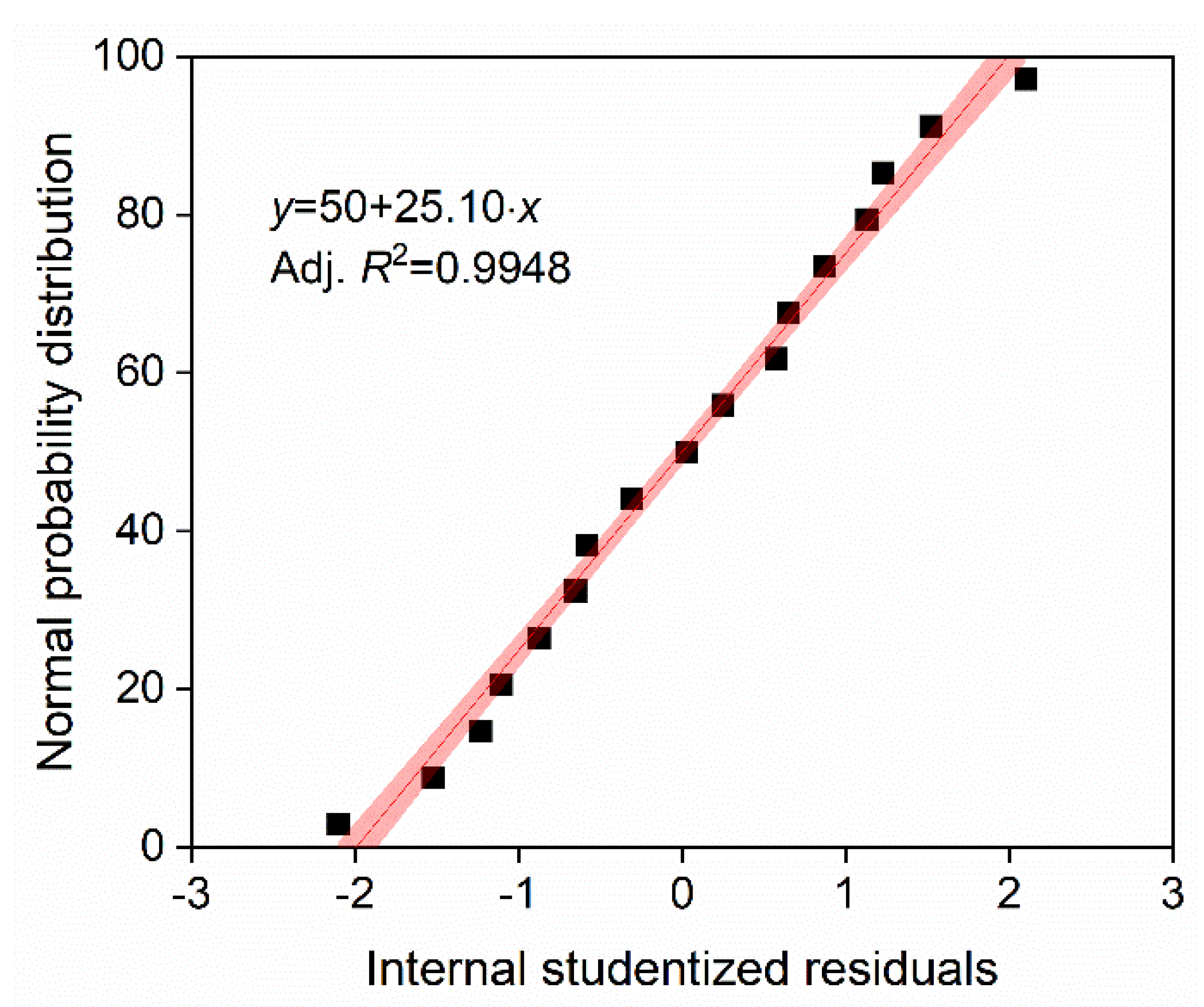
3.2. Analysis of Wet Ball-Milling Experiment Results

The content of −0.074 mm in the ground product was used as the evaluation index to obtain the experimental results of the Box–Behnken response surface design, as shown in Table 5. Using the Design-Expert software, the optimal grinding process parameters were determined and grinding test results were obtained.
In the Design-Expert software, the fitting effects of linear, 2FI, quadratic, and cubic models were compared, and the quadratic model for predicting experimental results was recommended (Table 6). Table 7 shows the results of ANOVA for the suggested model. The F-value of the suggested model was 11.10, meaning that it was significant and its chances of being disturbed were only 0.22%. Furthermore, the model fitted the experimental results well. In the suggested model, the values of R2, adjusted R2, and predicted R2 were 0.9345, 0.8503, and 0.2384, respectively, which indicated that the predicted value of the suggested model was consistent with the experimental results. The plot of the normal probability distribution of the internal studentized residuals in Figure 4 showed a straight line (adjusted R2 = 0.9948), indicating a high degree of confidence in the experimental results. It can be seen that the model recommended by the Design-Expert software can be used for the prediction and optimization of experimental results. The predicted model equation based on the experimental results is as follows:
γ−0.074 = 71.58 + 15.93A − 7.59B + 0.0316C + 1.47AB + 0.832AC + 5.38BC − 6.05A2 − 13.28B2 + 4.82C2
A 3D response surface graph based on predicted model equations can illustrate the effect of the interaction between different factors on the γ−0.074 mm [19]. Figure 5 illustrates the 3D response surface graph. As can be seen in Figure 5a, the slope of the response surface curve of factor B (grinding concentration) first rose and then fell; the slope of the response surface curve for factor A (grinding time) showed an increasing trend. In comparison, the slope of the response surface curve for factor A was steeper than that of factor B, which indicated that the effect of factor A on γ−0.074 mm was more significant than that of factor B. As shown in Figure 5b, the slope of the response surface curve for factor A was significantly greater than that for factor C (ball diameter), demonstrating that the effect of factor A on γ−0.074 mm was also more significant than that of factor C. The effect of factor B on γ−0.074 mm was more remarkable than that of factor C (Figure 5c). The significance of the three factors, in descending order, was A > B > C, which is consistent with the ANOVA results.
The maximum value of γ−0.074 mm predicted by the model was 87.89%, corresponding to the experimental conditions of 60 min grinding time, 60% grinding concentration, and 2 cm ball diameter. The value of γ−0.074 mm obtained from the grinding experiment under optimal conditions was 89.98%. The deviation between the predicted and experimental values was 2.33%, indicating that the predicted model was reliable.
To analyze the mechanism of ball milling for carbon anode slag, the particle shape of 0.5–0.25 mm of the raw ore and the sample under optimal grinding conditions were examined using a microscope, and a comparison of the results is presented in Figure 6. As shown in Figure 6b, the surfaces of the particles of 0.5–0.25 mm after grinding were smooth and there were no long strips of particles after grinding. However, as shown in Figure 6a, a certain number of long strips of particles were clearly presented in the carbon anode slag before grinding. The results in Figure 6 indicate that the carbon anode slag was mainly ground by the abrasion mechanism during the wet ball-milling process. This conclusion is also supported by the literature [16,20].

3.3. Analysis of Flotation Recovery Results of Ground Products

The multi-stage flotation process was carried out on the −0.074 mm ground product under optimal grinding conditions, and the results are presented in Table 8.
As can be seen from Table 8, the purity of cryolite could be upgraded to 93.12% by flotation after grinding the raw carbon anode slag to −0.074 mm, which was 40% (actually 40 percentage points) higher than the raw ore. Moreover, the recovery of cryolite was 59.00%. The reason for the improved grade of cryolite is that the low-ash product with a content of 40.16% was removed from the carbon anode slag. The low-ash product contained dry basis 10.67% ash 84.37% fixed carbon, and 4.96% volatile content, indicating that the product was mainly carbon, approximately 10% cryolite and 5% volatiles. It was determined that the low-ash product had a calorific value of 7171.60 kcal/kg, indicating that it could be recovered and used as fuel. In addition, carbon recovery was calculated to be around 71.99%. Therefore, a conventional grinding process followed by multi-stage flotation resulted in about 60% recovery of cryolite and about 70% of carbon in this study. Although the conventional grinding-flotation process can obtain high-purity cryolite and low-ash carbon, some cryolite and carbon cannot be fully recovered, mainly corresponding to the locked bodies of middlings. The middlings (tailings 5-tailings 2) in Table 8 are mainly non-liberated cryolite and carbon in the carbon anode slag. SEM-EDS images of the flotation middlings are shown in Figure 7. There was a small amount of fully dissociated cryolite particles (in the upper right corner). At the same time, it can be clearly seen that most of the particles were in the co-associated state of carbon and cryolite particles. The average particle size (d50) of the flotation middlings in this co-associated state was 17.11 μm (see Figure 8). It can be concluded that even if the particle size of the carbon anode slag is ground to smaller than 20 µm (d50), there are still some particles that are not completely dissociated.
The size of steel balls commonly used in ball milling is 3–5 cm [21]. In the process of ball milling, it is difficult to realize the complete dissociation of the middlings involved in this study by using steel balls in this scale range. This is because the size of the grinding medium is too large compared with the particle size of the grinding object to provide enough grinding surface to realize the dissociation of fine middlings [19,22]. In order to crush and dissociate the flotation middlings effectively, they can be pulverized through ultra-fine grinding, such as with stirred mill [23] and scrubbing pre-treatment [19]. After the deep dissociation of the flotation middlings (d50 = 17.11 μm), the particle size of the products will inevitably be finer. While the finer products cannot be effectively recovered using conventional flotation methods [24], for the recovery of fine mineral particles, possible effective methods include carrier flotation [25,26,27], micro-nano bubble flotation [28,29], hydrophobic flocculation flotation [30,31], oil agglomeration [32,33], etc. It should be noted that the research on deep dissociation and efficient recovery of flotation middlings needs to be further explored.

4. Conclusions

(1) The d50 of raw carbon anode slag with an ash content of 53.54% was about 1 mm, and contained the elements of F, Na, Al, etc., and the non-carbon material was mainly cryolite. The particle size of the carbon particles embedded with cryolite was less than 100 μm in the raw slag. Therefore, it is necessary to realize the dissociation of carbon particles and cryolite through suitable grinding.
(2) Under optimal conditions (60 min grinding time, 60% grinding concentration, 2 cm ball diameter), the predicted and experimental values of γ−0.074 mm were 87.89% and 89.98%, respectively. The deviation between the predicted and experimental values was 2.33%, showing that the predicted model recommended by the Design-Expert software was reliable. The order of significant effects of different factors on γ−0.074 mm was: grinding time > grinding concentration > ball diameter.
(3) Under optimal grinding conditions, the ground product with particle size less than 0.074 mm was separated by the multi-stage flotation process to obtain the cryolite product with a purity of 93.12% (recovery of 59.00%). The low calorific value of the carbon product (recovery of 71.99%) was as high as 7171.60 kcal/kg, which can be used as fuel.
(4) A combination of conventional grinding and flotation can effectively recover both carbon and cryolite from spent carbon anode slag. However, this method cannot recover all the carbon and cryolite, mainly because of the presence of a fraction of incompletely dissociated carbon and cryolite particles. The study on the deep dissociation and efficient recovery of these fine particles needs to be given more attention.

Author Contributions

Conceptualization and funding acquisition, C.N. and X.W.; resources, methodology, formal analysis, and funding acquisition, G.X.; software and validation, J.Z., S.W. and X.W.; investigation, Z.Z.; data curation, S.Y. and C.J.; writing—original draft preparation, J.Z. and S.W.; writing—review and editing and visualization, X.W. and M.B.; supervision and project administration, C.N. All authors have read and agreed to the published version of the manuscript.

Funding

This work was supported by the Undergraduate Training Program for Innovation and Entrepreneurship, China University of Mining and Technology (No. 202110290253H) and the Science and Technology Project of Shanxi Institute of Technology (No. 2022QD-05). This work was also funded by the Postdoctoral Innovation Project of Shandong Province in 2021 (No. 142).

Data Availability Statement

Not applicable.

Acknowledgments

The authors wish to sincerely thank Huaizhi Shao for his valuable contributions to this work.

Conflicts of Interest

The authors declare no conflict of interest.

References

  1. Ying, L.; Dengpeng, C.; Wei, W.; Dongsheng, L.; Junwei, W.; Yudong, L.; Zhirong, S. Influences of heat treatment on the oxidation and corrosion behavior of Cu–Ni–Fe inert anodes for aluminium electrolysis. J. Alloy Compd. 2020, 832, 154848. [Google Scholar] [CrossRef]
  2. Hussein, A.; Fafard, M.; Ziegler, D.; Alamdari, H. Effects of Charcoal Addition on the Properties of Carbon Anodes. Metals 2017, 7, 98. [Google Scholar] [CrossRef]
  3. Ishak, R.; Laroche, G.; Lamonier, J.-F.; Ziegler, D.P.; Alamdari, H. Characterization of Carbon Anode Protected by Low Boron Level: An Attempt To Understand Carbon–Boron Inhibitor Mechanism. ACS Sustain. Chem. Eng. 2017, 5, 6700–6706. [Google Scholar] [CrossRef]
  4. Li, B.; Zhou, J.; Yao, Z.; Peng, Q.; Liu, M.; Li, X.; Liu, W. Advances in the Safe Disposal and Comprehensive Utilization of Spent Carbon Anode From Aluminum Electrolysis: Prospects for Extraction and Application of Carbon Resources From Hazardous Waste. Front. Energy Res. 2021, 9, 1–10. [Google Scholar] [CrossRef]
  5. National Directory of Hazardous Wastes, Ministry of Ecology and Environment of the People’s Republic, China. Available online: https://www.mee.gov.cn/gzk/gz/202112/t20211213_963867.shtml (accessed on 1 January 2021).
  6. Institute, I.A. Primary aluminium production. Available online: https://international-aluminium.org/statistics/primary-aluminium-production/ (accessed on 21 November 2022).
  7. Ni, C.; Zhou, S.; Gao, J.; Bu, X.; Chen, Y.; Alheshibri, M.; Xie, G.; Li, B. Selective comminution and grinding mechanisms of spent carbon anode from aluminum electrolysis using ball and rod mills. Physicochem. Probl. Miner. Process. 2022, 58, 1–15. [Google Scholar] [CrossRef]
  8. Li, H.; Wang, J.; Hou, W.; Li, M.; Cheng, B.; Feng, Y.; Xu, T. The Study of Carbon Recovery from Electrolysis Aluminum Carbon Dust by Froth Flotation. Metals 2021, 11, 145. [Google Scholar] [CrossRef]
  9. Wang, Y.; Wang, X.; Bilal, M. Recovery of carbon and cryolite from spent carbon anode slag of electrolytic aluminum by flotation based on the evaluation of selectivity index. Front. Chem. 2022, 10, 1025990. [Google Scholar] [CrossRef]
  10. Yang, K.; Gong, P.; Xin, X.; Tian, Z.; Lai, Y. Purifying spent carbon anode (SCA) from aluminum reduction industry by alkali fusion method to apply for Li-ion batteries anodes: From waste to resource. J. Taiwan Inst. Chem. Eng. 2020, 116, 121–127. [Google Scholar] [CrossRef]
  11. Kuang, B.; Zhang, F.; Yu, Y.; Yang, S.; Liu, H.; Wang, H.; Hu, J. Co-treatment of spent carbon anode and copper slag for reuse and the solidification of the constituent fluorine and heavy metals. J. Clean. Prod. 2023, 383, 135418. [Google Scholar] [CrossRef]
  12. Gao, J.; Tong, Z.; Bu, X.; Bilal, M.; Hu, Y.; Ni, C.; Xie, G. Effect of water-in-oil and oil-in-water with Span 80 on coal flotation. Fuel 2023, 337, 127145. [Google Scholar] [CrossRef]
  13. Mei, X.; Li, J.; Yu, Z. The research on recycling carbon residue by floatation process. Light Met. 2016, 4, 28–30. [Google Scholar]
  14. Tangsathitkulchai, C.; Austin, L. The effect of slurry density on breakage parameters of quartz, coal and copper ore in a laboratory ball mill. Powder Technol. 1985, 42, 287–296. [Google Scholar] [CrossRef]
  15. Deniz, V. The effects of ball filling and ball diameter on kinetic breakage parameters of barite powder. Adv. Powder Technol. 2012, 23, 640–646. [Google Scholar] [CrossRef]
  16. Bu, X.; Chen, Y.; Ma, G.; Sun, Y.; Ni, C.; Xie, G. Wet and dry grinding of coal in a laboratory-scale ball mill: Particle-size distributions. Powder Technol. 2020, 359, 305–313. [Google Scholar] [CrossRef]
  17. Bu, X.; Ma, G.; Peng, Y.; Xie, G.; Zhan, H.; Liu, B. Grinding kinetics of coal in wet ball-milling using the Taguchi method. Int. J. Coal Prep. Util. 2022, 42(3), 369–388. [Google Scholar] [CrossRef]
  18. Chen, Y.; Li, P.; Bu, X.; Wang, L.; Liang, X.; Chehreh Chelgani, S. In-depth purification of spent pot-lining by oxidation-expansion acid leaching—A comparative study. Sep. Purif. Technol. 2022, 303, 122313. [Google Scholar] [CrossRef]
  19. Wang, X.; Bu, X.; Ni, C.; Zhou, S.; Yang, X.; Zhang, J.; Alheshibri, M.; Peng, Y.; Xie, G. Effect of scrubbing medium’s particle size on scrubbing flotation performance and mineralogical characteristics of microcrystalline graphite. Miner. Eng. 2021, 163, 106766. [Google Scholar] [CrossRef]
  20. Bu, X.; Chen, Y.; Ma, G.; Sun, Y.; Ni, C.; Xie, G. Differences in dry and wet grinding with a high solid concentration of coking coal using a laboratory conical ball mill: Breakage rate, morphological characterization, and induction time. Adv. Powder Technol. 2019, 30, 2703–2711. [Google Scholar] [CrossRef]
  21. Rao, D.S. Mineral Beneficiation: A Concise Basic Course; CRC Press: Boca Raton, FL, USA, 2011. [Google Scholar]
  22. Wang, X.; Bu, X.; Alheshibri, M.; Bilal, M.; Zhou, S.; Ni, C.; Peng, Y.; Xie, G. Effect of scrubbing medium’s particle size distribution and scrubbing time on scrubbing flotation performance and entrainment of microcrystalline graphite. Int. J. Coal Prep. Util. 2022, 42, 3032–3053. [Google Scholar] [CrossRef]
  23. Prziwara, P.; Thake, S.; Breitung-Faes, S.; Kwade, A. Comparison of open and closed circuit mode using a dry horizontal stirred media mill with special regard to the powder flowability and residence time distribution. Miner. Eng. 2021, 163, 106781. [Google Scholar] [CrossRef]
  24. Miettinen, T.; Ralston, J.; Fornasiero, D. The limits of fine particle flotation. Miner. Eng. 2010, 23, 420–437. [Google Scholar] [CrossRef]
  25. Eckert, K.; Schach, E.; Gerbeth, G.; Rudolph, M. Carrier Flotation: State of the Art and its Potential for the Separation of Fine and Ultrafine Mineral Particles. In Materials Science Forum; Trans Tech Publications Ltd.: Durnten-Zurich, Switzerland, 2019; Volume 959, pp. 125–133. [Google Scholar]
  26. Wang, X.; Zhou, S.; Bu, X.; Ni, C.; Xie, G.; Peng, Y. Investigation on interaction behavior between coarse and fine particles in the coal flotation using focused beam reflectance measurement (FBRM) and particle video microscope (PVM). Sep. Sci. Technol. 2021, 56, 1418–1430. [Google Scholar] [CrossRef]
  27. Zhou, S.; Wang, X.; Bu, X.; Wang, M.; An, B.; Shao, H.; Ni, C.; Peng, Y.; Xie, G. A novel flotation technique combining carrier flotation and cavitation bubbles to enhance separation efficiency of ultra-fine particles. Ultrason. Sonochem 2020, 64, 105005. [Google Scholar] [CrossRef]
  28. Zhang, Z.; Ren, L.; Zhang, Y. Role of nanobubbles in the flotation of fine rutile particles. Miner. Eng. 2021, 172, 107140. [Google Scholar] [CrossRef]
  29. Zhou, S.; Li, Y.; Nazari, S.; Bu, X.; Hassanzadeh, A.; Ni, C.; He, Y.; Xie, G. An Assessment of the Role of Combined Bulk Micro- and Nano-Bubbles in Quartz Flotation. Minerals 2022, 12, 944. [Google Scholar] [CrossRef]
  30. Besson, A.; Formosa-Dague, C.; Guiraud, P. Flocculation-flotation harvesting mechanism of Dunaliella salina: From nanoscale interpretation to industrial optimization. Water Res. 2019, 155, 352–361. [Google Scholar] [CrossRef]
  31. Ni, C.; Zhang, Q.; Jin, M.; Xie, G.; Peng, Y.; Yu, H.; Bu, X. Effect of high-speed shear flocculation on the flotation kinetics of ultrafine microcrystalline graphite. Powder Technol. 2022, 396, 345–353. [Google Scholar] [CrossRef]
  32. Kumar, S.; Chary, G.H.V.C.; Dastidar, M.G. Optimization studies on coal–oil agglomeration using Taguchi (L16) experimental design. Fuel 2015, 141, 9–16. [Google Scholar] [CrossRef]
  33. Mehrotra, V.; Sastry, K.; Morey, B. Review of oil agglomeration techniques for processing of fine coals. Int. J. Miner. Process 1983, 11, 175–201. [Google Scholar] [CrossRef]
Figure 1. The multi-stage flotation process for spent carbon anode slag.
Separations 10 00193 g001
Figure 2. The XRD pattern of spent carbon anode slag.
Separations 10 00193 g002
Figure 3. Microscopic images of spent carbon anode slag sections. Notes: the black areas represent carbon particles.
Separations 10 00193 g003
Figure 4. Normal probability distribution as a function of internal studentized residuals.
Separations 10 00193 g004
Figure 5. 3D response surface plot of γ−0.074 mm as a function of the interaction: (a) grinding time × grinding concentration, 2.5 cm ball diameter; (b) grinding time × ball diameter, 60% grinding concentration; (c) solid concentration × ball diameter, 40 min grinding time.
Separations 10 00193 g005
Figure 6. Comparison of particle shape of 0.5–0.25 mm (a) before grinding and (b) after grinding. Notes: Long strips of particles are marked with red circles in Figure 6a.
Separations 10 00193 g006
Figure 7. SEM-EDS result of flotation middlings.
Separations 10 00193 g007
Figure 8. Laser particle size measurement results of flotation middlings.
Separations 10 00193 g008
Table 1. Levels of selected factors in this study (three factors and three levels).
SymbolFactorUnitLevel 1Level 2Level 3
AGrinding timemin20 (–1)40 (0)60 (1)
BGrinding concentration%40 (–1)60 (0)80 (1)
CBall diametercm3 (–1)2.5 (0)2 (1)
Table 2. Experimental design of Box–Behnken response surface.
No.A—Grinding Time (min)B—Grinding Concentration (wt.%)C—Ball Diameter (cm)
120 (−1)80 (1)2.5 (0)
260 (1)40 (−1)2.5 (0)
360 (1)60 (1)3 (1)
440 (0)60 (1)2.5 (0)
540 (0)60 (1)2.5 (0)
660 (1)80 (1)2.5 (0)
740 (0)80 (1)2 (−1)
820 (−1)60 (1)2 (−1)
940 (0)40 (−1)2 (−1)
1020 (−1)60 (1)3 (1)
1120 (−1)40 (−1)2.5 (0)
1240 (0)60 (1)2.5 (0)
1360 (1)60 (1)2 (−1)
1440 (0)80 (1)3 (1)
1540 (0)40 (−1)3 (1)
1640 (0)60 (1)2.5 (0)
1740 (0)60 (1)2.5 (0)
Table 3. Particle size composition of spent carbon anode slag.
Size (mm)Yield (%)Ash Content (%)Accumulation under Sieve
Yield (%)Ash Content (%)
3–149.8652.16100.0053.54
1–0.526.3151.7750.1454.91
0.5–0.259.7957.1823.8358.39
0.25–0.1257.2859.7914.0459.23
0.125–0.0743.0458.666.7658.62
<0.0743.7258.593.7258.59
Total100.0053.54--
Table 4. The XRF results of spent carbon anode slag.
FNaMgAlSiPSClKCaTiVMnFeNiCuGaSr
59.1717.160.144.740.710.061.180.130.701.690.010.020.010.270.090.010.010.01
Table 5. Experimental results of Box–Behnken response surface design.
No.A-Grinding Time (min)B-Grinding Concentration (wt.%)C-Ball Diameter (cm)γ−0.074 mm
(%)
120 (−1)80 (1)2.5 (0)29.87
260 (1)40 (−1)2.5 (0)71.67
360 (1)60 (1)3 (1)83.43
440 (0)60 (1)2.5 (0)60.70
540 (0)60 (1)2.5 (0)65.65
660 (1)80 (1)2.5 (0)63.79
740 (0)80 (1)2 (−1)43.79
820 (−1)60 (1)2 (−1)58.90
940 (0)40 (−1)2 (−1)74.10
1020 (−1)60 (1)3 (1)49.03
1120 (−1)40 (−1)2.5 (0)43.63
1240 (0)60 (1)2.5 (0)77.65
1360 (1)60 (1)2 (−1)89.98
1440 (0)80 (1)3 (1)62.89
1540 (0)40 (−1)3 (1)71.68
1640 (0)60 (1)2.5 (0)72.92
1740 (0)60 (1)2.5 (0)71.74
Table 6. Summary of fit goodness of model statistics.
SourceStd. Dev.R2Adjusted R2Predicted R2PRESS
Linear10.280.64440.56240.33302578.88
2FI11.170.67730.4837−0.33655167.45
Quadratic6.010.93450.85030.23842944.52Suggested
Cubic4.380.98020.9207 +Aliased
Notes: PRESS: Prediction Error of Square Sum; + case (s) with leverage of 1.000.
Table 7. Analysis of variance of the model suggested by Design-Expert software.
SourceSum of SquaresDFMean SquareF-ValueProb > FRemarks
Model3613.169401.4611.100.0022significant
A2030.1312030.1356.130.0001significant
B461.371461.3712.760.0091significant
C8.004 × 10−318.004 × 10−32.213 × 10−40.9885
AB8.6218.620.240.6403
AC2.7712.770.0770.7901
BC115.751115.753.200.1168
A2154.591154.594.270.0775
B2742.321742.3220.520.0027significant
C297.74197.742.700.1442
Residual253.17736.17
Lack of fit176.55358.853.070.1533not significant
Pure Error76.62419.16
Cor Total3866.3316
Table 8. The multi-stage flotation test results of −0.074 mm in the ground product.
ProductsYield (%)Ash Content (%)Concentrate AccumulationTailings Accumulation
Yield
(%)
Ash Content (%)Yield (%)Ash Content (%)
Concentrate40.169.5740.169.57100.0049.55
Tailings 54.4419.5144.6110.5659.8476.39
Tailings 43.6231.7248.2312.1555.3980.95
Tailings 38.6954.9556.9218.6851.7784.40
Tailings 211.6882.8868.6029.6143.0890.34
Tailings 131.4093.12100.0049.5531.4093.12
Total100.0049.55
Disclaimer/Publisher’s Note: The statements, opinions and data contained in all publications are solely those of the individual author(s) and contributor(s) and not of MDPI and/or the editor(s). MDPI and/or the editor(s) disclaim responsibility for any injury to people or property resulting from any ideas, methods, instructions or products referred to in the content.

