
Implementation of an Automated Manufacturing Process for Smart Clothing: The Case Study of a Smart Sports Bra

 , and
, and 
Abstract
:1. Introduction
2. Case Study of Manufacturing Process Automation in Clothing and Textile Fields
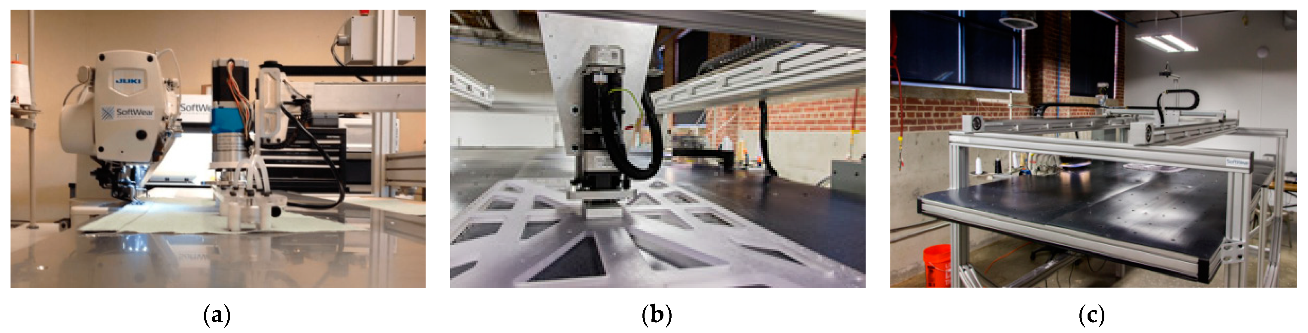
2.1. SEWBOT
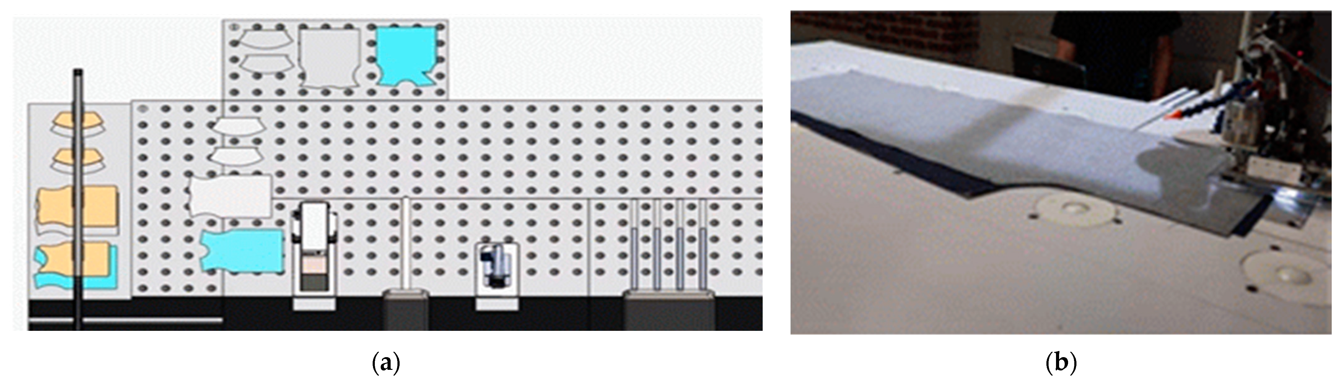
2.2. Micro-Factory
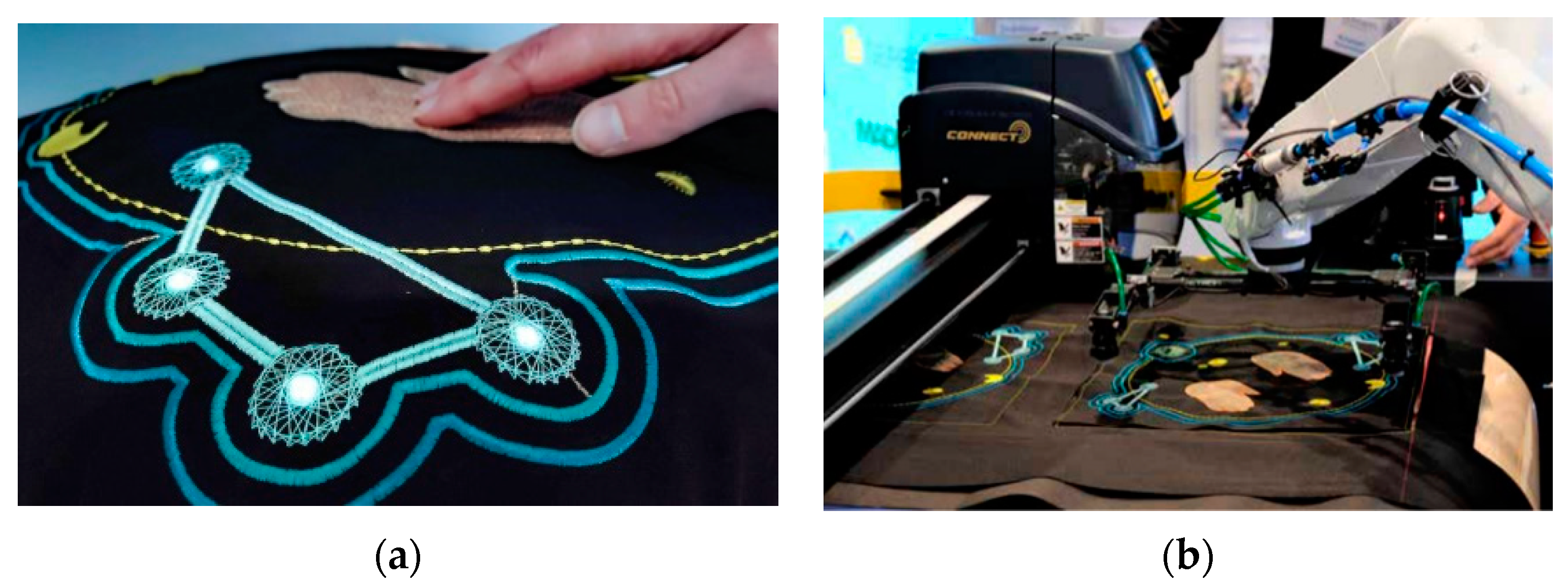
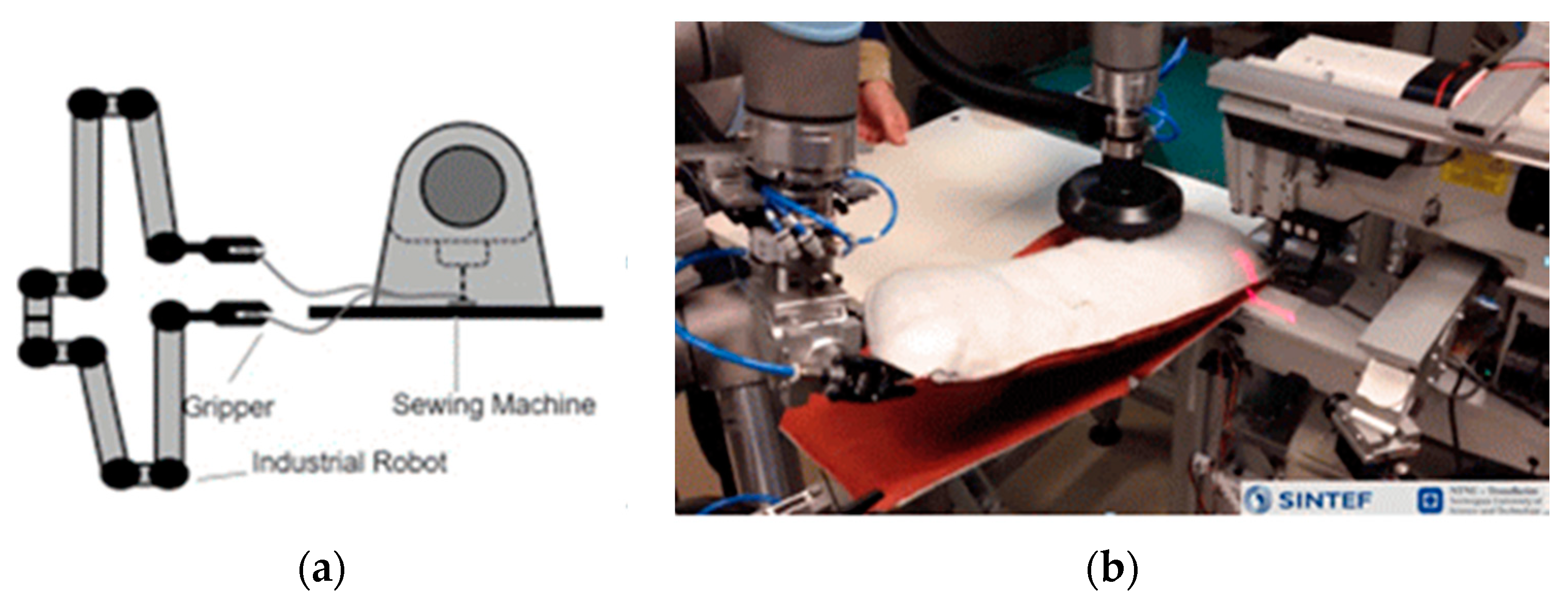
2.3. Robotic-Guided Sewing Project in SINTEF Raufoss Manufacturing
3. Automatic Manufacturing Process for Smart Clothing
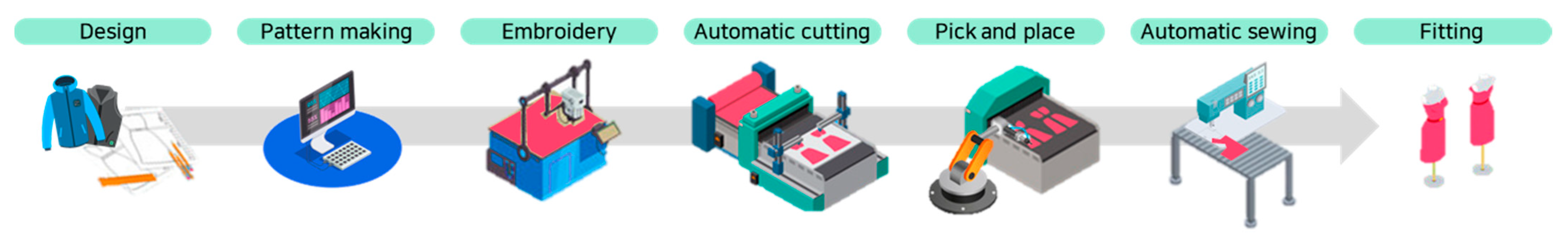
3.1. Making Process Framework
3.2. Design and Pattern Making through CAD/CAM Systems
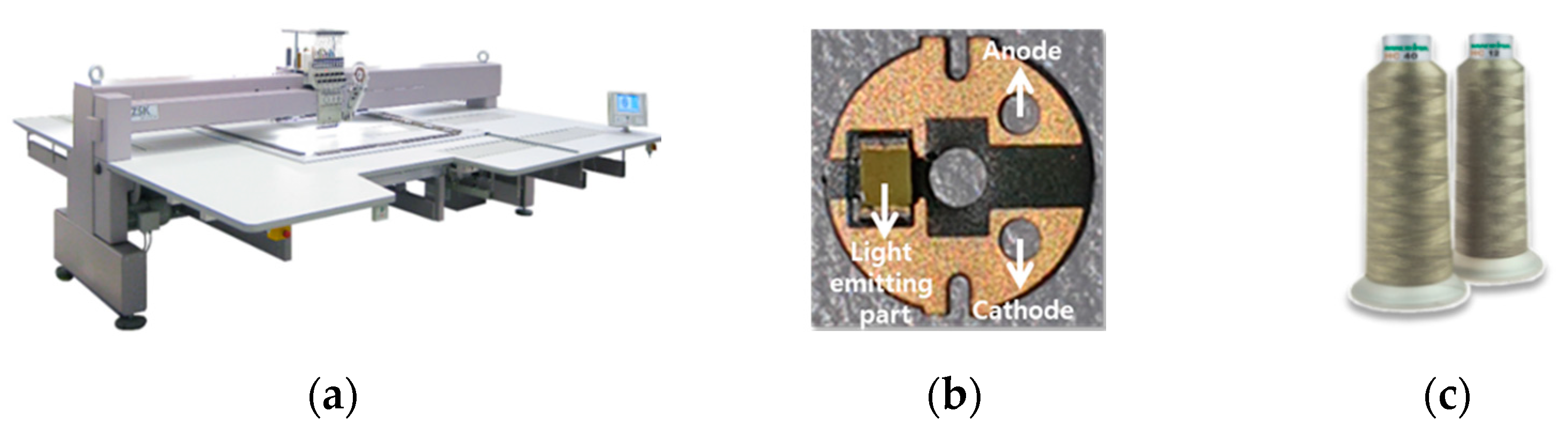
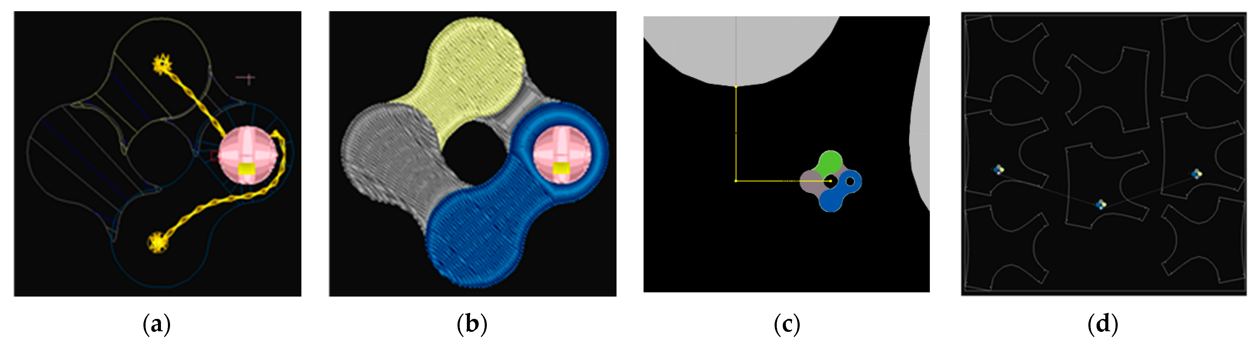
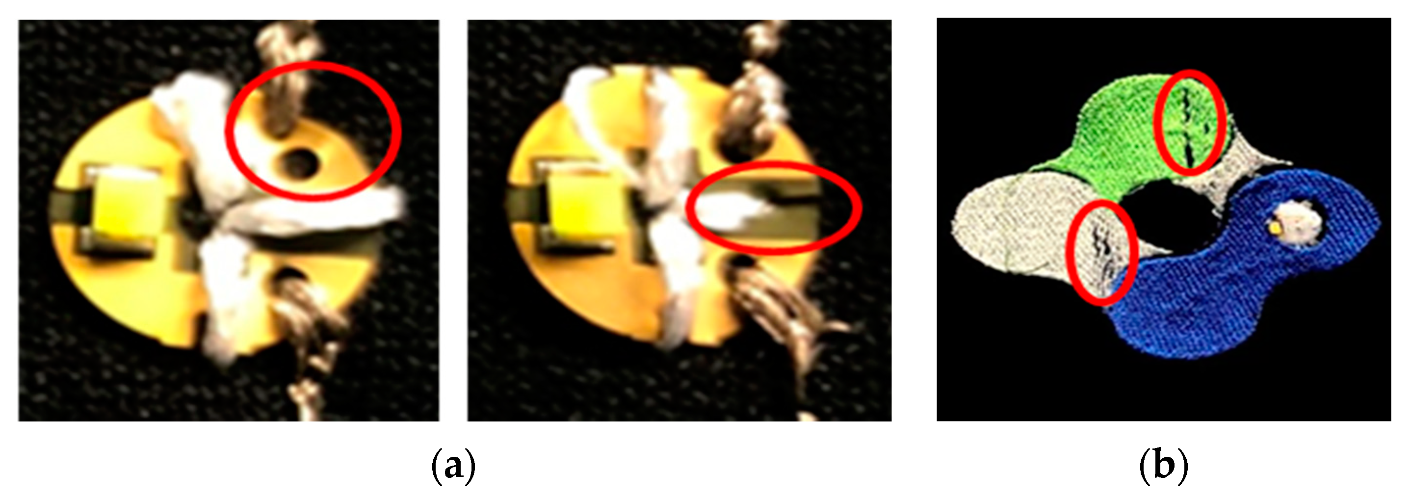
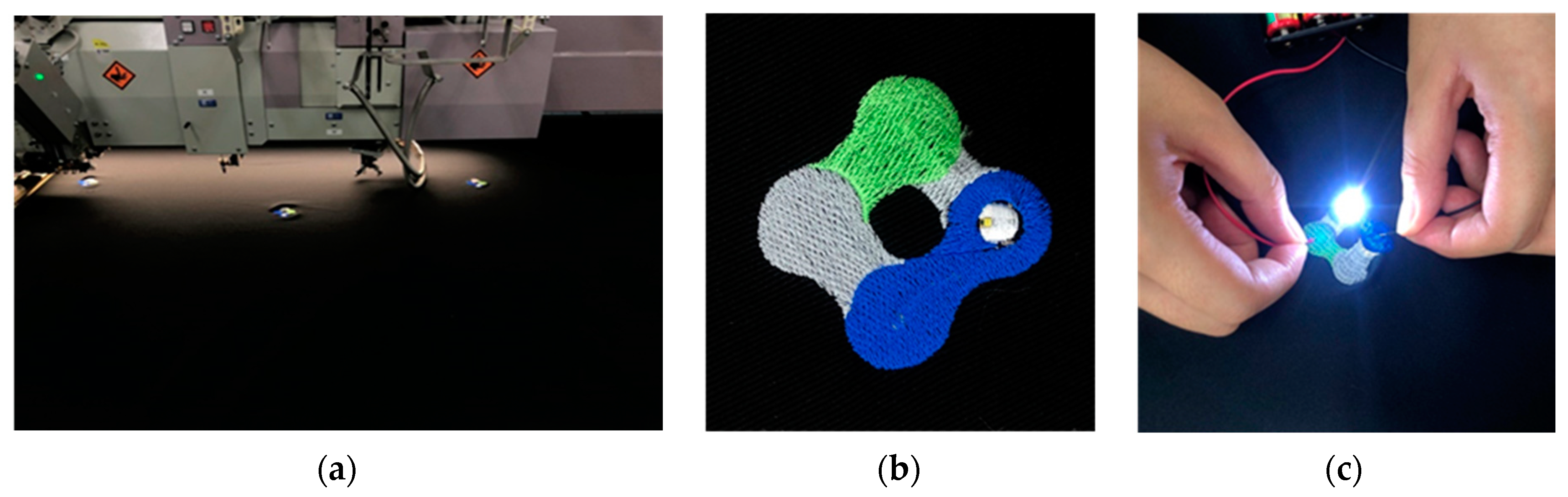
3.3. Embroidery for Smart Function
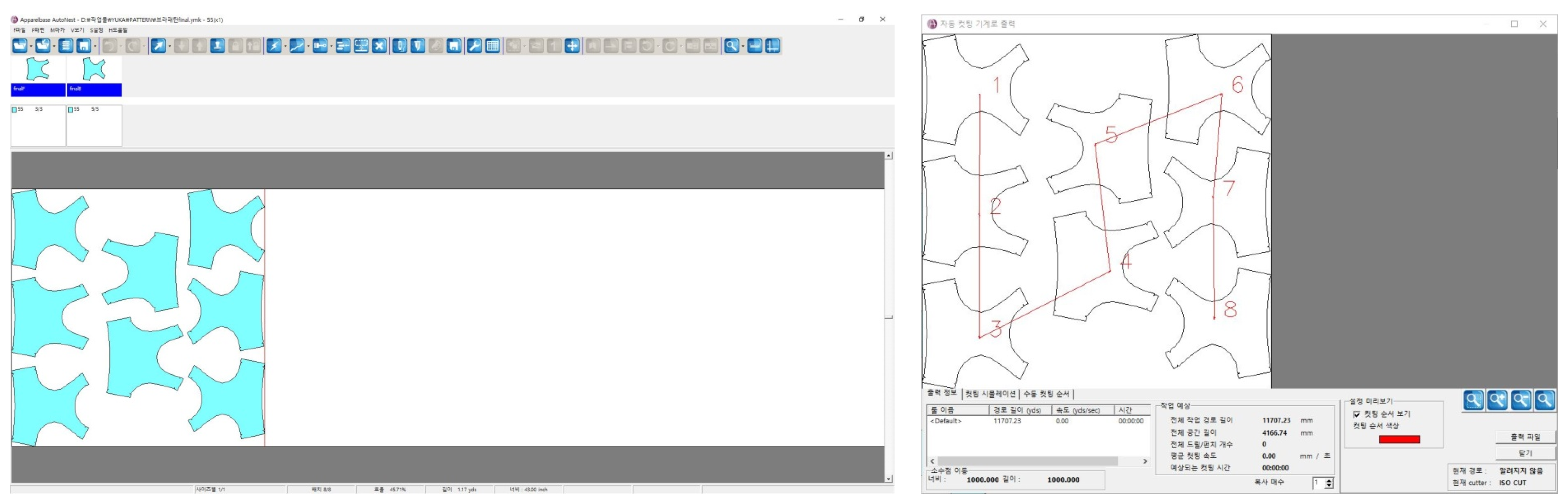
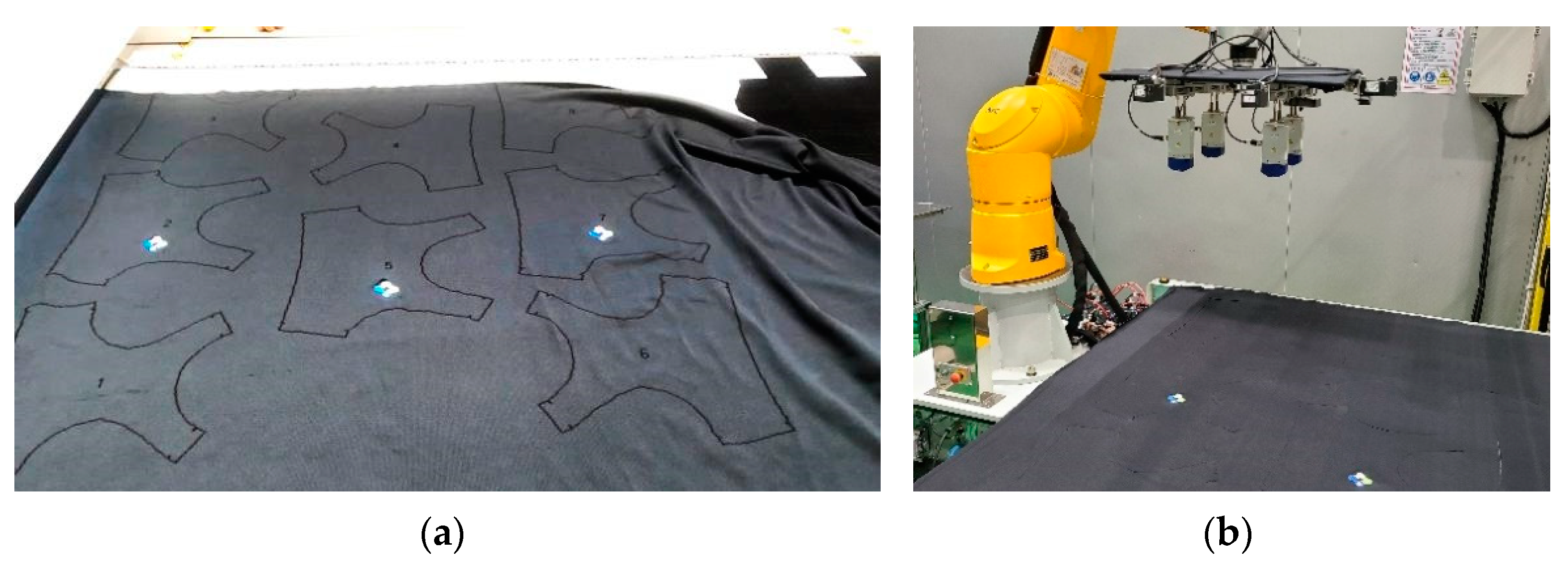
3.4. Automatic Cutting Process
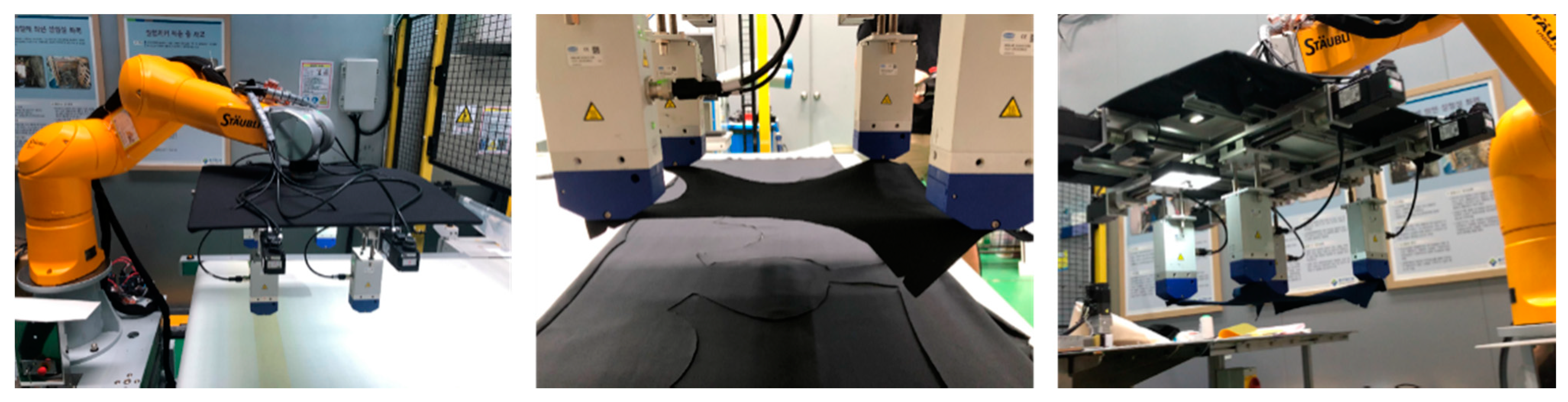
3.5. Robot Handling with a Gripping System
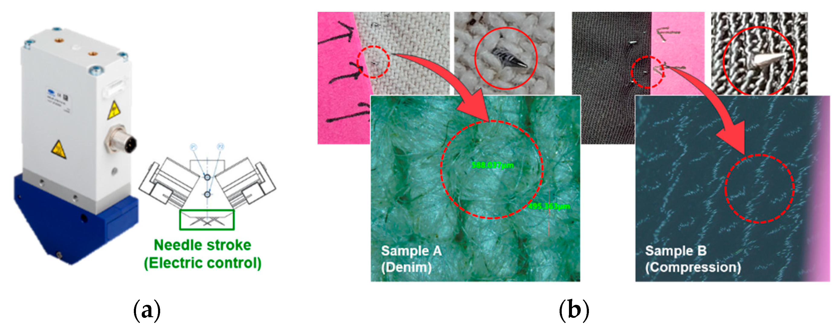
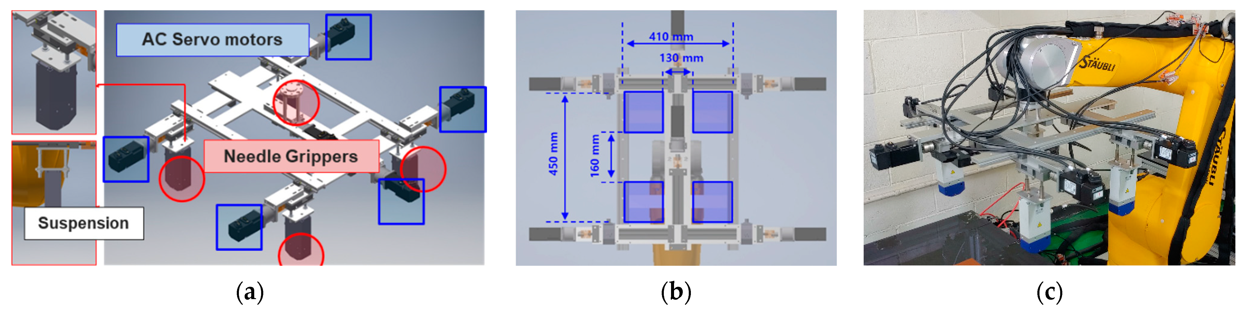
3.5.1. Adaptive Fabric Gripping Module
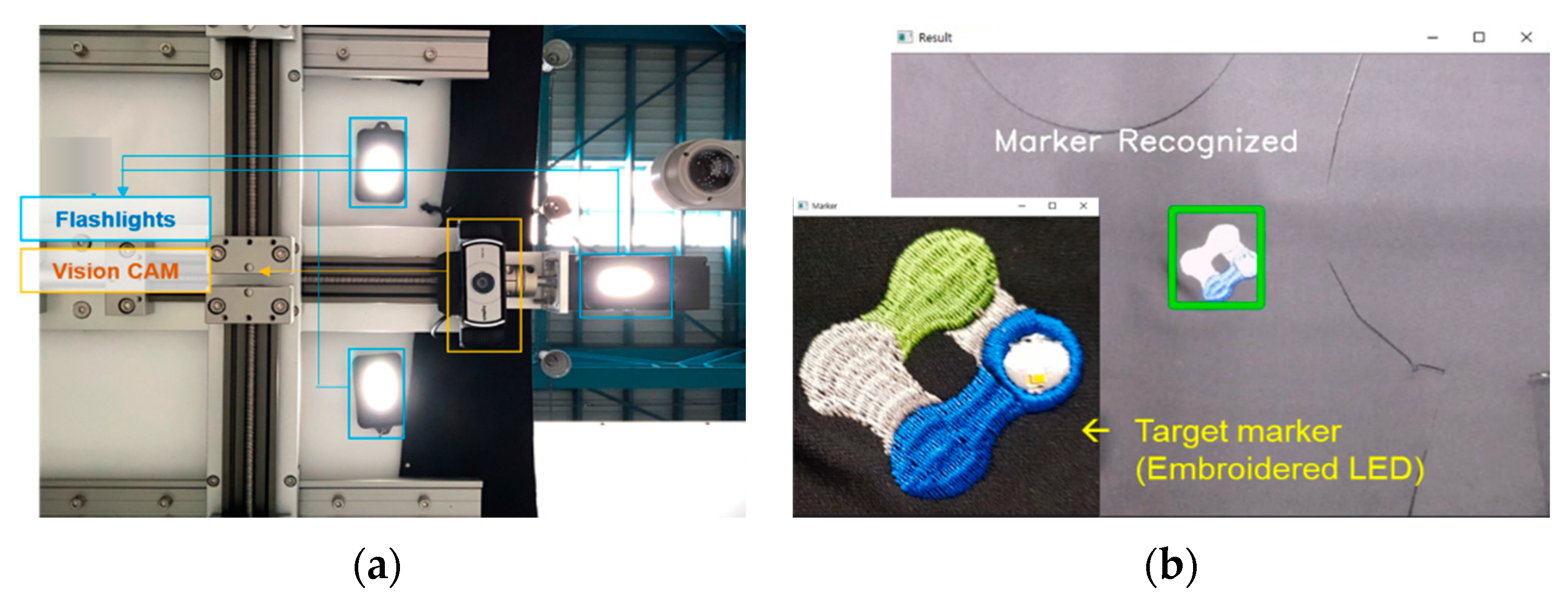
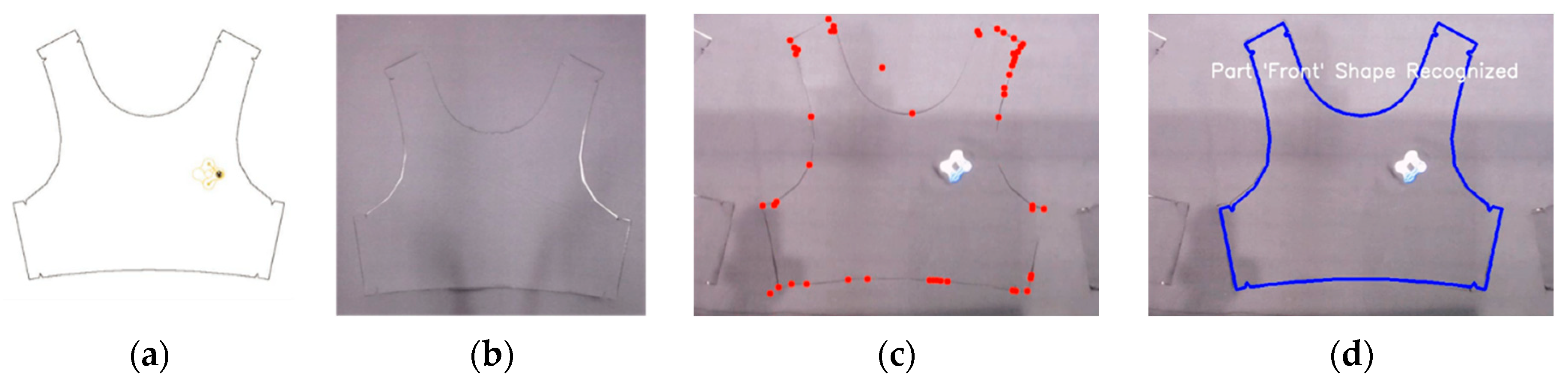
3.5.2. Vision-Based Shape Recognition Module
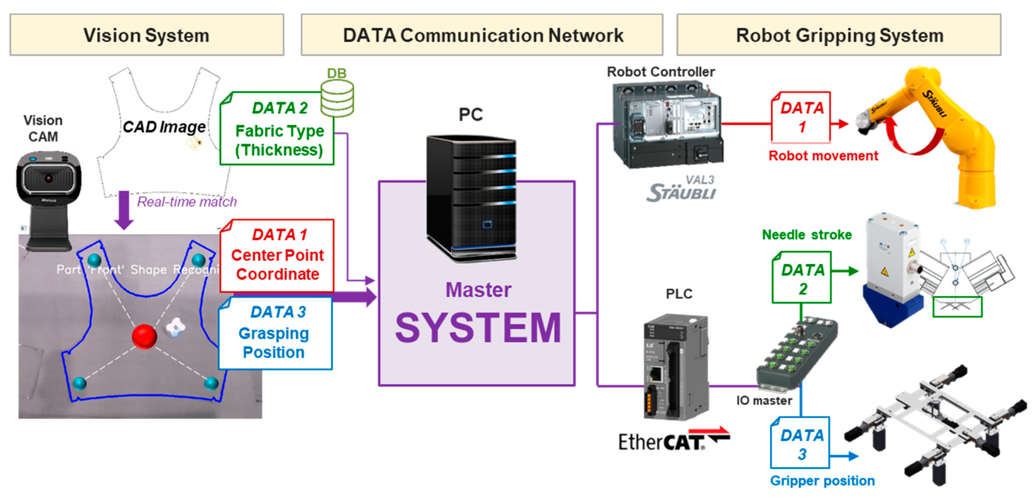
3.5.3. Data Communication Module and Total System Development
- PC to Robot: Transmits the x, y coordinates of the target’s center point by Ethernet-based socket communication
- PC to Grippers: Transfers the specified stroke length of needle gripper using Ethernet/IP communication
- PC to Jig (AC servomotors): Sends the determined gripper positions through Ethernet for control automation technology(EtherCAT) communication
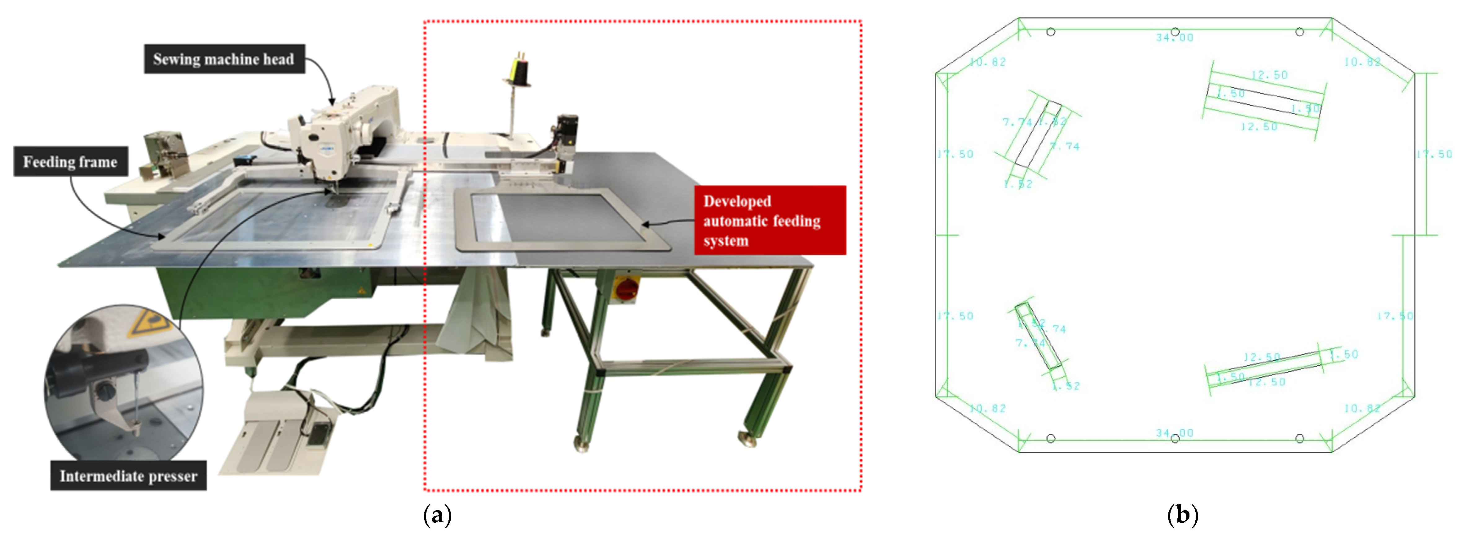
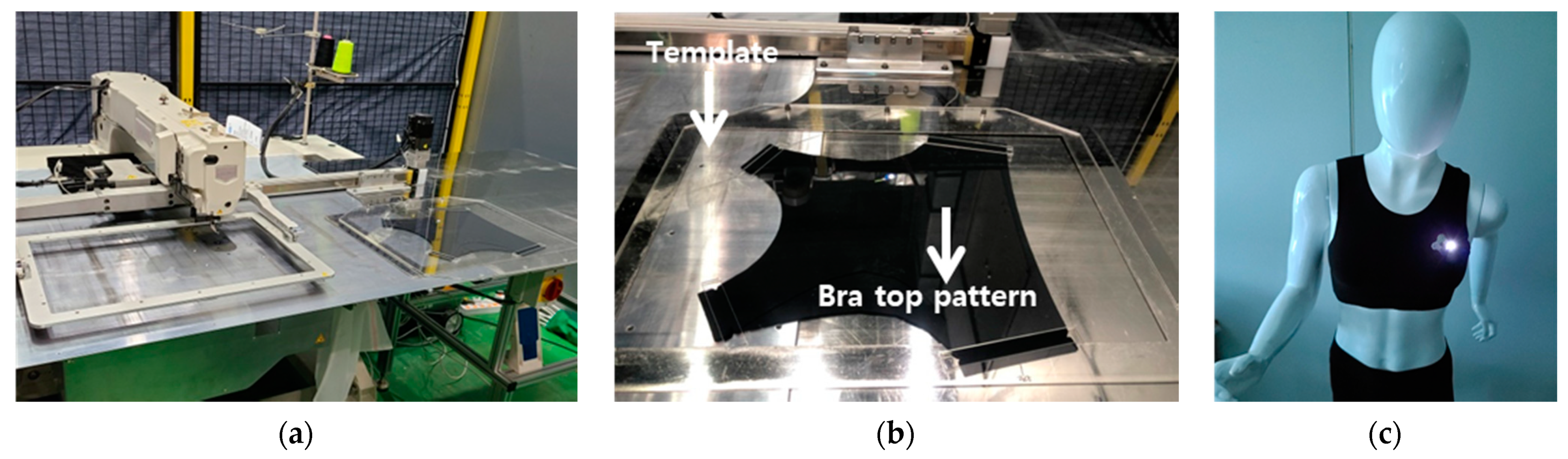
3.6. Automatic Sewing
4. Conclusions and Future Work
Author Contributions
Funding
Institutional Review Board Statement
Informed Consent Statement
Data Availability Statement
Conflicts of Interest
References
- Kim, J.C.; Moon, I.Y. A study on smart factory construction method for efficient production management in sewing industry. J. Inf. Commun. Converg. Eng. 2020, 18, 61–68. [Google Scholar]
- Teunissen, J.; Bertola, P. Fashion 4.0 innovation fashion industry through digital transformation. Res. J. Text. Appar. 2018, 22, 352–369. [Google Scholar]
- Nayak, R.; Padhye, R. Automation in Garment Manufacturing; Woodhead Publishing: Duxford, UK, 2018; pp. 1–290. [Google Scholar]
- CB Insight. The Future of Fashion: From Design to Merchandising, How Tech Is Reshaping the Industry. Available online: https://www.cbinsights.com/research/fashion-tech-future-trends/ (accessed on 13 October 2020).
- Santos, P.M.M.; Campiho, R.D.S.G.; Silva, F.J.G. Design of a novel equipment for automated clothing manufacturing. Procedia Manuf. 2018, 17, 766–773. [Google Scholar] [CrossRef]
- Kondratas, A. Robotic gripping device for garment handling operations and its adaptive control. Fibers Text. East. Eur. 2005, 13, 84–89. [Google Scholar]
- Fleischer, J.; Förster, F.; Crispieri, N.V. Intelligent gripper technology for the handling of carbon fiber material. Prod. Eng. Res. Dev. 2014, 8, 691–700. [Google Scholar] [CrossRef]
- Koustoumpardis, P.N.; Nastos, K.X.; Nikos, A.A. Underactuated 3-finger robotic gripper for grasping fabrics. In Proceedings of the 23rd International Conference on Robotics in Alpe-Adria Danube Region, Smolenice, Slovakia, 3–5 September 2014. [Google Scholar] [CrossRef]
- Ji, Y.; Schaerlaekens, M.; Terentjev, E.M.; Jones, I.; Lando, R.; Carosis, S.; Scalia, T.; Baglini, R.; Nostro, P.L.; Becheri, A.; et al. Innovative textile materials, stiffening procedures and fabric-joining methods. In Tranfroming Clothing Production into a Demand-Driven, Knowledge-Based, High-Tech Industry; Walter, L., Kartsounis, G.A., Carosio, S., Eds.; Springer: London, UK, 2009. [Google Scholar] [CrossRef]
- Ju, N.; Lee, K.H. Consumer resistance to innovation: Smart clothing. Fash. Text. 2020, 7. [Google Scholar] [CrossRef]
- Volker, L. Technical textiles: Smart textiles. In ITA Information Annual Report; Institue für Textiltechnik (ITA) der RWTH Aachen University: Aachen, Deutschland, 2019; pp. 14–15. [Google Scholar]
- Schrimpf, J.; Lind, M.; Mathisen, G. Work flow, material handling and initial part positioning in a multi-robot sewing cell. IFAC-Pap. Online 2015, 48, 45–50. [Google Scholar] [CrossRef]
- Luo, Z.G.; Yuen, M.M.F. Reactive 2D/3D garment pattern design modification. Comput. Aided Des. 2005, 37, 623–630. [Google Scholar] [CrossRef]
- Jhanji, Y. Computer-aided design: Garment designing and pattern making. In Automation in Garment Manufacturing; Rajkishore, N., Rajiv, P., Eds.; Woodhead Publishing: Duxford, UK, 2018; pp. 253–290. [Google Scholar]
- Size Korea. Available online: https://sizekorea.kr/board/article/view/4/8496 (accessed on 10 April 2018).
- Uchiyama, M.N.C.; Trouvat, P.; Moinier, H.M. ESMOD: Methode de Coupe_Vetements Feminins; ESMOD: Paris, France, 1999. [Google Scholar]
- Jeong, Y.H. Pattern development of tight-fitting pants for men using measurement of Size Korea 2004. Korean J. Hum. Ecol. 2006, 15, 791–802. [Google Scholar]
- Mecnika, V.; Hoerr, M.; Krievins, I.; Jockenhoevel, S.; Gries, T. Technical embroidery for smart textiles. Mater. Sci. Text. Cloth. Technol. 2014, 9, 56–63. [Google Scholar]
- Selm, B.A.R.B.E.L.; Bischoff, B.; Seidl, P. Embroidery and smart textiles. In Smart Fibres, Fabrics and Clothing: Fundamentals and Applications; Woodhead Publishing: Duxford, UK, 2001; pp. 218–225. [Google Scholar]
- Post, E.R.; Orth, M.; Russo, P.R.; Gershenfeld, N. Embroidery: Design and fabrication of textile-based computing. IBM Syst. J. 2000, 39, 840–860. [Google Scholar] [CrossRef]
- Weigel, M.; Lu, T.; Baily, G.; Oulasvirta, A.; Majidi, C.; Steimle, J. Iskin: Flexible, stretchable and visually customizable on-body touch sensors for mobile computing. In Proceedings of the CHI’15: 33rd Annual ACM Conference on Human Factors in Computing Systems, Seoul, Korea, 18–23 April 2015; Association for Computing Machinery: New York, NY, USA, 2015; pp. 2991–3000. [Google Scholar]
- Berk, G.G. Design of a wearable pain management system with embroidered TENS electrodes. Int. J. Cloth. Sci. Technol. 2018, 30, 38–48. [Google Scholar] [CrossRef]
- Moradi, B.; Fernández-García, R.; Gil, I. E-Textile embroidered metamaterial transmission line for signal propagation control. Materials 2018, 11, 955. [Google Scholar] [CrossRef] [PubMed] [Green Version]
- Arca, G. Seam performance of garments. Text. Manuf. Process. 2019. [Google Scholar] [CrossRef] [Green Version]
- Koustoumpardis, P.N.; Aspragathos, N.A. A review of gripping devices for fabric handling. In Proceedings of the International Conference on Intelligent Manipulation and Grasping, Genova, Italy, 1–2 July 2004; pp. 229–234. [Google Scholar]
- Sun, B.; Zhang, X. A new electrostatic gripper for flexible handling of fabrics in automated garment manufacturing. In Proceedings of the IEEE 15th International Conference on Automation Science and Engineering (CASE), Vancouver, BC, Canada, 22–26 August 2019; pp. 879–884. [Google Scholar]
- Le, T.H.L.; Jilich, M.; Landini, A.; Zoppi, M.; Zlatanov, D.; Molfino, R. On the development of a specialized flexible gripper for garment handling. J. Autom. Control Eng. 2013, 1, 255–259. [Google Scholar] [CrossRef] [Green Version]
- Marullo, S.; Bartoccini, S.; Salvietti, G.; Iqbal, M.Z.; Prattichizzo, D. The mag-gripper: A soft-rigid gripper augmented with an electromagnet to precisely handle clothes. IEEE Robot. Autom. Lett. 2020, 5, 6591–6598. [Google Scholar] [CrossRef]
- Burns, L.D.; Mullet, K.K.; Bryant, N.O. The Business of Fashion: Designing, Manufacturing, and Marketing, 5th ed.; Bloomsbury Publishing: London, UK, 2016. [Google Scholar]


Publisher’s Note: MDPI stays neutral with regard to jurisdictional claims in published maps and institutional affiliations. |
© 2021 by the authors. Licensee MDPI, Basel, Switzerland. This article is an open access article distributed under the terms and conditions of the Creative Commons Attribution (CC BY) license (http://creativecommons.org/licenses/by/4.0/).
Share and Cite
Lee, S.; Rho, S.H.; Lee, S.; Lee, J.; Lee, S.W.; Lim, D.; Jeong, W. Implementation of an Automated Manufacturing Process for Smart Clothing: The Case Study of a Smart Sports Bra. Processes 2021, 9, 289. https://doi.org/10.3390/pr9020289
Lee S, Rho SH, Lee S, Lee J, Lee SW, Lim D, Jeong W. Implementation of an Automated Manufacturing Process for Smart Clothing: The Case Study of a Smart Sports Bra. Processes. 2021; 9(2):289. https://doi.org/10.3390/pr9020289
Chicago/Turabian StyleLee, Suhyun, Soo Hyeon Rho, Sojung Lee, Jiwoong Lee, Sang Won Lee, Daeyoung Lim, and Wonyoung Jeong. 2021. "Implementation of an Automated Manufacturing Process for Smart Clothing: The Case Study of a Smart Sports Bra" Processes 9, no. 2: 289. https://doi.org/10.3390/pr9020289