Article

Cavitation Prevention Potential of Hydromechanical Pressure Compensation Independent Metering System with External Active Load

School of Mechanical Engineering, Jiangsu University of Technology, Changzhou 213001, China
*
Author to whom correspondence should be addressed.
Processes 2021, 9(2), 255; https://doi.org/10.3390/pr9020255
Submission received: 19 December 2020 / Revised: 21 January 2021 / Accepted: 26 January 2021 / Published: 29 January 2021
(This article belongs to the Section Chemical Processes and Systems)

Abstract

:
This article studies the cavitation performance and preventing method of the hydromechanical pressure compensation independent metering system (HPCIMS). Compared with the conventional load sensing system (CLSS), the meter-in and meter-out orifices of HPCIMS can be regulated independently. A quasi-static behavior analysis of cavitation performance was applied to the HPCIMS and CLSS. The meter-in pressure equation of HPCIMS showed that keeping the ratio of the meter-in and meter-out orifices greater than the minimum value can avoid the cavitation phenomenon. Systems parameters were then kept as constant, and the key parameters related to cavitation performance of the two systems were compared by varying external force. Comparison results show that the cavitation phenomenon in the meter-in chamber of CLSS with the external active load is inevitable, but in HPCIMS, it can prevent the cavitation phenomenon by changing the ratio of the meter-in and meter-out orifices, so the HPCIMS has the cavitation prevention potential.

1. Introduction

Due to the unique and valuable characteristics, hydraulic systems are widely used for a variety of applications ranging from construction to industrial, military, aerospace, and earth moving applications [1,2]. The mobile hydraulic system, which is one of the typical hydraulic systems, has many demanding requirements, like changing environment, limited space, and higher power/weight, and so on [3]. Generally, the proportional directional spool valves are widely used in the mobile hydraulic system to control the flow direction and flow rate of the actuator [4]. A sliding spool is adopted in the proportional directional spool valve, so the meter-in orifice and meter-out orifice are mechanically linked. For example, the conventional load sensing system is a typical mobile hydraulic system, which is widely used in construction machinery and agricultural machinery. The proportional directional spool valve is used in the conventional load sensing system, which makes the system easy to control, but it also brings in some significant limitations, such as energy losses and nonlinearities, which make the control system more challenging [5]. In the conventional mobile load sensing system, about 30% of the energy losses are due to the friction and hysteresis of the proportional directional spool valves [6].
In order to overcome the shortcomings of the traditional hydraulic system, A. Jansson and J. O. Palmberg proposed a hydraulic system using four 2/2-valves to control an actuator independently; it breaks the mechanical linkage and decouples the restriction [7]. In this system, the motion control of the actuator can be realized by actuating two of the four 2/2-valves. Compared with the conventional load sensing system, the independent metering configuration has brought many functions due to the decoupling of meter-in and meter-out orifices, including regeneration functionality, float functionality, energy-saving functionality, and cavitation prevention functionality [8]. The development of independent metering technology is technically and economically attractive, and it can replace the traditional hydraulic technology [9]. The independent metering technology can be realized by many available valve configurations, for example, five 2/2-valves, two 3/3-valves, a combination of two 3/3-valves and one 2/2-valve [10]. Different valve configurations require different control logics and corresponding control methods for desired actuator motion control. Many previous researchers have investigated the independent metering technology. B. Yao adopted five electro-hydraulic proportional cartridge valves complete trajectory tracking and energy-saving control by robust adaptive control algorithm [11,12,13]. Hu H and Zhang Q using a programmable E/H valve with a hybrid control algorithm, realize the multifunction [14,15]. Moreover, good energy-saving characteristics of excavators with the independent metering system must be obtained by using different control methods [16,17,18].
Compared with the conventional hydraulic system, the independent metering system is a multiple-input and multiple-output system, so it requires a more complex control method for motion and displacement control. In the mobile hydraulic system, the motion of the actuator needs to be consistent with the input signal of a joystick, so the flow rate passing through the main control valve must be controlling. There are two control methods for flow rate control: the electro-hydraulic pressure compensation method and the hydromechanical pressure compensation method. The electro-hydraulic pressure compensation method needs more sensors and a complex control algorithm for realizing the motion control. As opposed to the electro-hydraulic pressure compensation method, the hydromechanical pressure compensation method reacts directly and rapidly to disturbance variables in the system due to using the hydraulic pressure compensator [19]. Compared with the traditional load sensing system, the load sensing system with hydromechanical pressure compensation and independent metering offers more significant energy savings [20].
Compared with the conventional hydraulic system, the independent metering system has a very important function is that can prevent the cavitation phenomenon by regulating the meter-in and meter-out orifices. As well known, the cavitation phenomenon takes place due to local evaporation of the fluid caused by a lowering of the pressure. If the pressure falls below the vapor pressure of the fluid, the steam bubble is created, and the bubbles reach regions of higher pressure, it will be generated pressure waves and caused erosion [21]. The cavitation may occur in the pumps, valves, actuators, and pipes of the hydraulic system, and it will result in severe damage to the hydraulic components and the whole hydraulic system [22,23,24,25].
In the hydraulic system, there are two kinds of external load: external passive load and external active load. With the external passive load, the motion direction of the actuator is opposite to the direction of the external load; it will hinder the movement of the actuator. In the meter-in chamber and meter-out chamber of the actuator with external passive load, it will not be easy to produce cavitation. With the external active load, the motion direction of the actuator is the same as the direction of the external load, and it will drive the movement of the actuator. If the external active load is great than a certain value, the pressure of the meter-in chamber of the actuator will fall below the vapor pressure, as a result, will be produced the cavitation phenomenon. In the conventional load sensing system with greater external active load, the cavitation phenomenon is inevitable. However, in the independent metering system, the cavitation phenomenon can be avoided by regulating the meter-in and meter-out orifices [10].
Many scholars have studied the independent metering system for a long time, but the research related to the cavitation performance analysis of the independent metering system is still very rare. This study focuses on the quasi-static behavior of the hydromechanical pressure compensation independent metering system with external active load and ignores the dynamic effects. Cavitation performance and preventing method of the hydromechanical pressure compensation independent metering system are investigated in this paper.
The remainder of this paper is organized as follows: Section 2 introduces the main layouts and the working principles of the hydromechanical pressure compensation independent metering system and conventional load sensing system, respectively. Section 3 presents the cavitation performance analysis of the hydromechanical pressure independent metering system and conventional load sensing system. The quasi-static behavior equations of the two systems with external active load are deduced in detail in Section 3, as well as the preventing cavitation method of the hydromechanical pressure independent metering system is proposed. Section 4, system parameters are kept constant, and the cavitation performances of the hydromechanical pressure independent metering system and conventional load sensing system are presented for the sake of comparison. Section 5 concludes the paper by discussing the cavitation prevention applicability and further work of the hydromechanical pressure independent metering system.

2. System Layouts and Working Principle

2.1. Working Principle

The principle of a spool valve controls a cylinder is shown in Figure 1. As is shown in Figure 1, the sliding spool x of the spool valve plays an important role in the system that can control the flow direction and the flow rate. When the sliding spool s is moving to the left location, the high-pressure oil flows from the port P of the spool valve to the head chamber of the cylinder, the flow rate of metering in the orifice is Qa, and then the high-pressure oil pushes the cylinder piston rod to extend. As a result, the low-pressure oil flows the rod chamber of the cylinder to the port T of the spool valve, the flow rate of metering out orifice is Qb. When the sliding spool s is moving to the right location, the cylinder piston rod can be realized retraction motion.
It can be seen that the flow rate of meter-in orifice Qa and the flow rate of meter-out orifice Qb are controlled simultaneously by the sliding spool s. However, the flow rate of meter-in orifice Qa can determine the velocity v of the cylinder piston rod, so the decrease of the meter-out orifice by the sliding spool motion is redundant because it caused repeated throttling losses.
To overcome the shortcomings of the conventional spool valve control system, the independent metering control system is has appeared. The principle of the independent metering control system is shown in Figure 2. It can be seen that the spool valve of the conventional spool valve control system is replaced by four spool valves #1, #2, #3 and #4. When the sliding spool s1 is moving to the left location, the high-pressure oil flows from the shared port P of the spool valve #1 and #3 to the head chamber of the cylinder. Then the high-pressure oil pushes the cylinder piston rod to extend, and simultaneously, the sliding spool s4 regulates the meter-out orifice. As a result, the low-pressure oil flows out of the rod chamber of the cylinder to the share port T of the spool valve #2 and #4. The flow rate of the meter-in orifice of spool valve #1 is Qa, and the flow rate of the meter-out orifice of spool valve #4 is Qb. When the sliding spool s3 and s2 are moving to the left location, the cylinder piston rod can be realized retraction motion.
Hence, compared with the conventional spool valve control system, the independent metering system has two control degrees whether the cylinder piston rod is extending or retracting. When the flow rate of metering in the orifice of spool valve #1 is controlled by the sliding spool s1, the sliding spool s4 can move to the maximum position to reduce the repeated throttling losses as soon as possible. Finally, it can achieve energy saving.
There are many hydraulic system layouts that can realize the independent metering system. Figure 3 shows the two typical kinds of hydraulic system layouts. Figure 3a shows the four 2/2-valves control system layouts. Figure 3b shows the two 3/3-valves controlled system layouts. However, the two typical hydraulic system layouts have different kinds of valves and various connection formations, but they both can reduce the repeated throttling losses for energy saving.

2.2. Electro-Hydraulic Pressure Compensation Method

In the independent metering system, the flow rate Q of the spool valve can also be expressed:
Q = C d W x 2 Δ P ρ
where Cd is the flow coefficient of the spool valve, W is the area gradient of the spool valve, x is the sliding spool displacement of the spool valve, ΔP is the differential pressure of the spool valve, and ρ is the density of the hydraulic fluid.
From Equation (1), the density of the hydraulic fluid ρ can be seen as a constant value. The parameter W is the area gradient of the spool valve, which is determined by the dimensions of the spool valve, so it can seem like a constant value when the spool valve is the same. The flow coefficient Cd equals 0.611 in the turbulent region [26], so it can be seen as a constant value because the turbulent flow existed in the valve control system. Hence, the differential pressure ΔP and the sliding spool displacement x can be changed for the desired flow rate Q. As a result, that obtaining the desired flow rate Q of the spool valve, there are two methods that can be accomplished. One method is called the electro-hydraulic pressure compensation method, which is changing the sliding spool displacement x by the electronic signal according to the differential pressure ΔP. Moreover, the other method is called the hydromechanical pressure compensation method, which is keeping the differential pressure ΔP as a constant value, change the sliding spool displacement x simultaneously.
The principle of the electro-hydraulic pressure compensation method is shown in Figure 4. The inlet valve and the outlet valve have separately controlled the flow rate of metering in orifice Qa and the flow rate of metering out orifice Qb. Three pressure sensors should be existed for detecting the pressure Ps, Pa, and Pb; the pressure P0 is approximately regarded as 0 because it is the tank pressure. In order to obtain the desired flow rate Q, it is necessary to control sliding spool displacement x by closed-loop feedback according to Equation (1), so two-spool displacement sensors should have existed.
The advantage of the electro-hydraulic pressure compensation method is that it reduces the repeated throttling losses because the inlet valve and outlet valve can be separately controlled, but the disadvantages, like more sensors needed, diagnostic points added, and closed-loop feedback control demanding, also has been brought out.

2.3. Hydromechanical Pressure Compensation Method

The principle of the hydromechanical pressure compensation method is shown in Figure 5. The pressure compensator, which is a hydraulic component, was adopted for keeping the differential pressure ΔP of the inlet valve as a constant value. Hence, from Equation (1), the density of the hydraulic fluid ρ, the area gradient W, and the flow coefficient Cd can be seen as constant values, when the differential pressure ΔP is constant due to the pressure compensator, the desired flow rate Q is proportional to the sliding spool displacement x. As a result, the spool displacement sensors are not required, and only two pressure sensors are needed for detecting the pressure Pa and Pb. Thus, the controller no need to detect the differential pressure ΔP and the sliding spool displacement x; it only needs to send control signals to the inlet valve and outlet valve separately.
Compared with the electro-hydraulic pressure compensation method, the hydromechanical pressure compensation method reduced one pressure sensor and two spool displacement sensors, so the failure rate of the control system will be lower. Moreover, the pressure compensator can keep the differential pressure ΔP of the inlet valve as a constant by the hydromechanical principle; it is more stable for the control system. However, the disadvantage of the hydromechanical pressure compensation method is that the pressure compensator brings a certain pressure loss.

2.4. HPCIMS Configuration

According to the principle of the hydromechanical pressure compensation method, the hydromechanical pressure compensation independent metering system (HPCIMS) can be designed. There are many configurations that can realize the HPCIMS, one of the configurations as is shown in Figure 6. The hydromechanical pressure compensation independent metering control block, which is integrating multiple valves, including five 2/2-valves, two switch 3/2-valves, a pressure compensator and a shuttle valve. The main role of the five 2/2-valves is to complete the extension and retraction motion of the cylinder. The pressure compensator can keep the differential pressure of the 2/2-valve #4 or 2/2-valve #5 as a constant value. The combination of the switch 3/2-valve #1, switch 3/2-valve #2 and shuttle valve can truly feedback the pressure of the two chambers of the cylinder to the port LS1.

2.5. CLSS Configuration

The conventional load sensing system (CLSS) is commonly used in construction machinery and agricultural machinery. Figure 7 shows the conventional load sensing control block that controls a cylinder. Compared with HPCIMS, the CLSS also has adopted a proportional directional spool 5/3-valve, a pressure compensator, a shuttle valve, and two proportional pressure reducing valves. The differential pressure of the proportional directional spool 5/3-valve is kept as a constant value by the pressure compensator. The proportional directional spool 5/3-valve has completed the motion direction control of the cylinder piston rod. The proportional pressure reducing valves #1 and #2 can control the sliding spool displacement. The pressure of the two chambers of the cylinder can feedback to the port LS1 by the proportional directional spool 5/3-valve and shuttle valve.

3. Cavitation Performance Analysis

3.1. Causes of Cavitation

The cylinder is the important hydraulic component in the hydraulic system; it can complete retraction and extension movements. When the piston of the cylinder is moving, the external force acting on the piston rod has two forms: external passive force and external active force. In actual applications of the cylinder, both passive and active load forces may be excessive. The consequence of excessive external passive load is that the piston rod of the hydraulic cylinder cannot move, which will cause the mechanical drive system to suspend. The consequence of excessive external active load is that one of the cylinder chambers will produce cavitation.
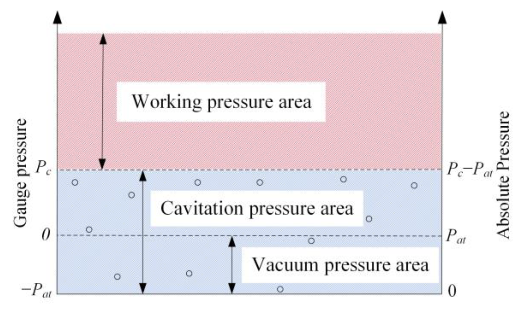
In the hydraulic system, the system pressure is generally the gauge pressure. As is shown in Figure 8, cavitation is a phenomenon, which can occur in the hydraulic system, such as pumps, valves, motors and cylinders, when the hydraulic system pressure falls below the vapor pressure Pc, which is the gauge pressure. The hydraulic system pressure area is divided into three areas: the working pressure area, cavitation pressure area and vacuum pressure area. It can be seen that the working pressure area is desired, as the hydraulic system pressure is greater than the vapor pressure Pc. Moreover, the cavitation pressure area is included the vacuum pressure; both of the cavitation pressure areas and vacuum pressure are not desired. As the hydraulic system pressure is less than the vapor pressure Pc, it will produce cavitation. If the hydraulic system pressure is less than 0, it will produce a vacuum, and the minimum value of the system pressure is the negative atmospheric pressure −Pat.
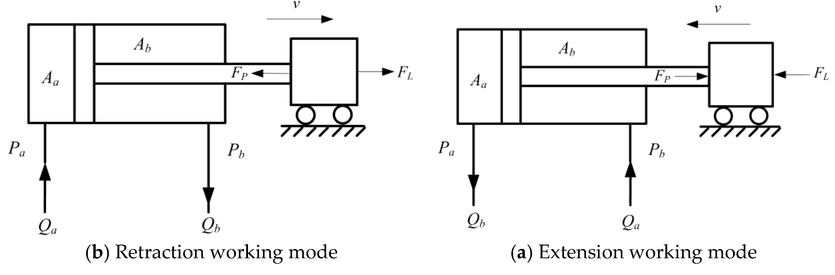
In the hydraulic system with external active load, both the extension working mode and retraction working mode will produce cavitation. Figure 8 shows two working modes with external active load. Figure 9a shows the extension working mode with external active load, and Figure 9b shows the retraction working mode with external active load. From Figure 9a,b, it can be seen that the direction of the external active load FL acting on the piston rod is the same as the direction of the cylinder piston speed v. The difference between extension working mode and retraction working mode is that the direction of the velocity v, the flow rate Qa and Qb, and the force FL and FP are opposite. Hence, take the extension working mode with external active load, for example, for analyzing the cavitation phenomenon.
As is shown in Figure 9a, the output force FP of the piston rod can be express:
F P = P b A b P a A a
where FP is the output force of the piston rod, Aa is the head chamber area of the cylinder, Ab is the cylinder rod chamber area, Pa is the cylinder head chamber pressure, Pb is the cylinder rod chamber pressure.
As is shown in Figure 9a, when the piston rod is extending with the external active load FL, the output force FP will be hindering the extension motion of the piston rod. The value of output force FP depends on the head chamber pressure Pa and rod chamber pressure Pb. If the rod chamber pressure Pb is growing to the maximum safe pressure of the hydraulic system, and the head chamber pressure Pa the negative atmospheric pressure −Pat. As a result, the output force FP will be growing to the maximum FPmax. Hence, in the hydraulic system, the output force FP must be less than the maximum out force FPmax.
When the external active load FL acting on the piston rod is less than the maximum out force FPmax, the force balance equation for the piston rod can be expressed:
F L = F P
In this situation, as Equation (3) is described, the velocity v of the cylinder piston rod is controlled by the hydraulic system, and it will not produce the cavitation phenomenon in the head chamber of the cylinder.
When the external active load FL is greater than the maximum out force FPmax, the force balance equation for the piston rod can be expressed:
F L F P = m a
where FL is the external active load acting on the piston rod, m is the total mass of the piston and load referred to the piston, a is the acceleration of the piston and load referred to the piston.
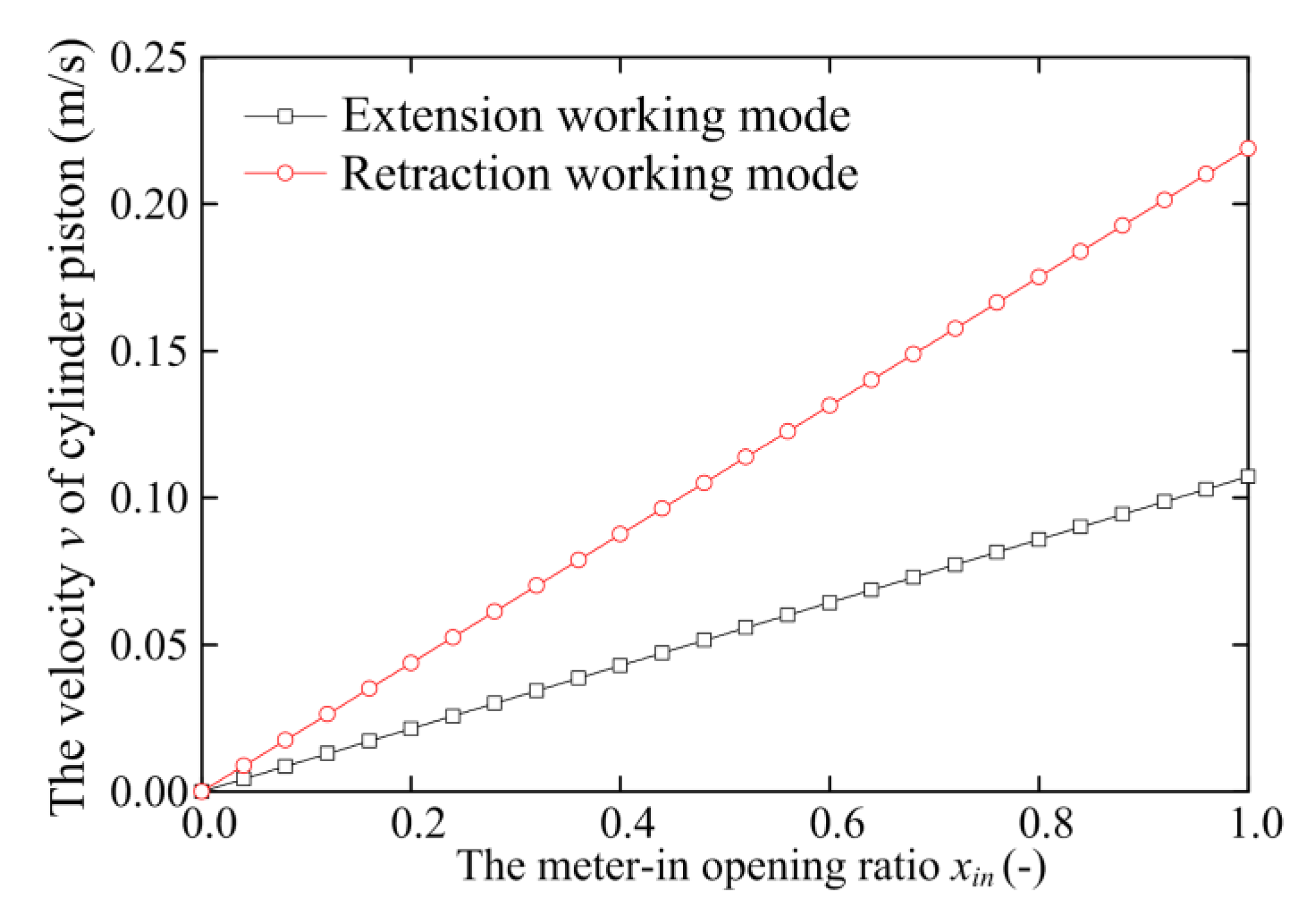
The velocity v of the piston can be expressed:
v = v 0 + a t
where v0 is the velocity when the external active load FL equals the output force FP of the piston rod, t is the acceleration time.
In this situation, as Equations (4) and (5) are described, the velocity v of the cylinder piston rod will be increasing with the acceleration time t. If the acceleration time t lasts too long, the velocity v will be increasing from velocity v0 to a great value vmax. Hence, the velocity v of the cylinder piston rod cannot be depending on the hydraulic system but on the external active load FL and the acceleration time t.
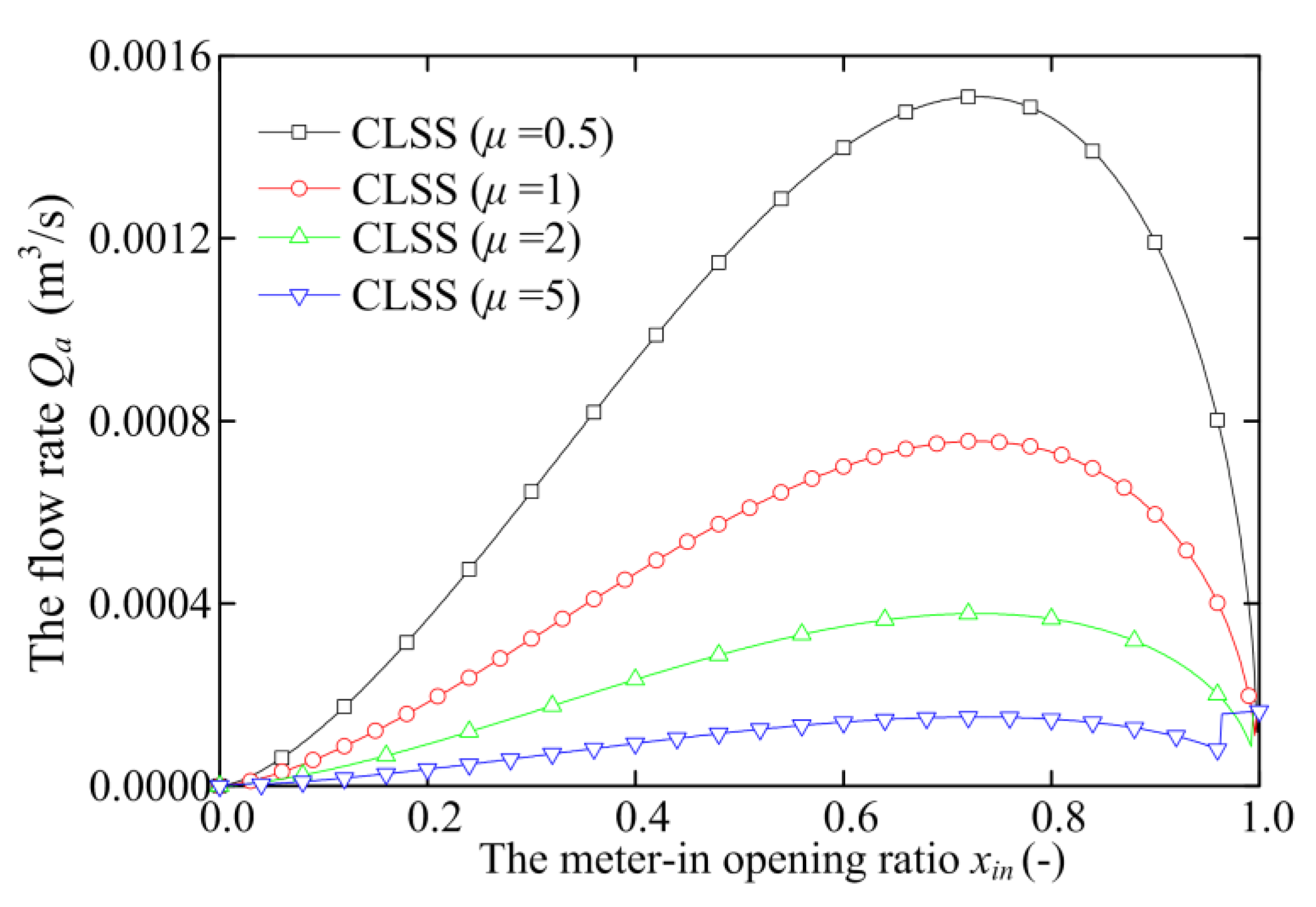
In the two working modes with external active load, if both of the cylinder rod chamber pressure Pb and the cylinder head chamber pressure 
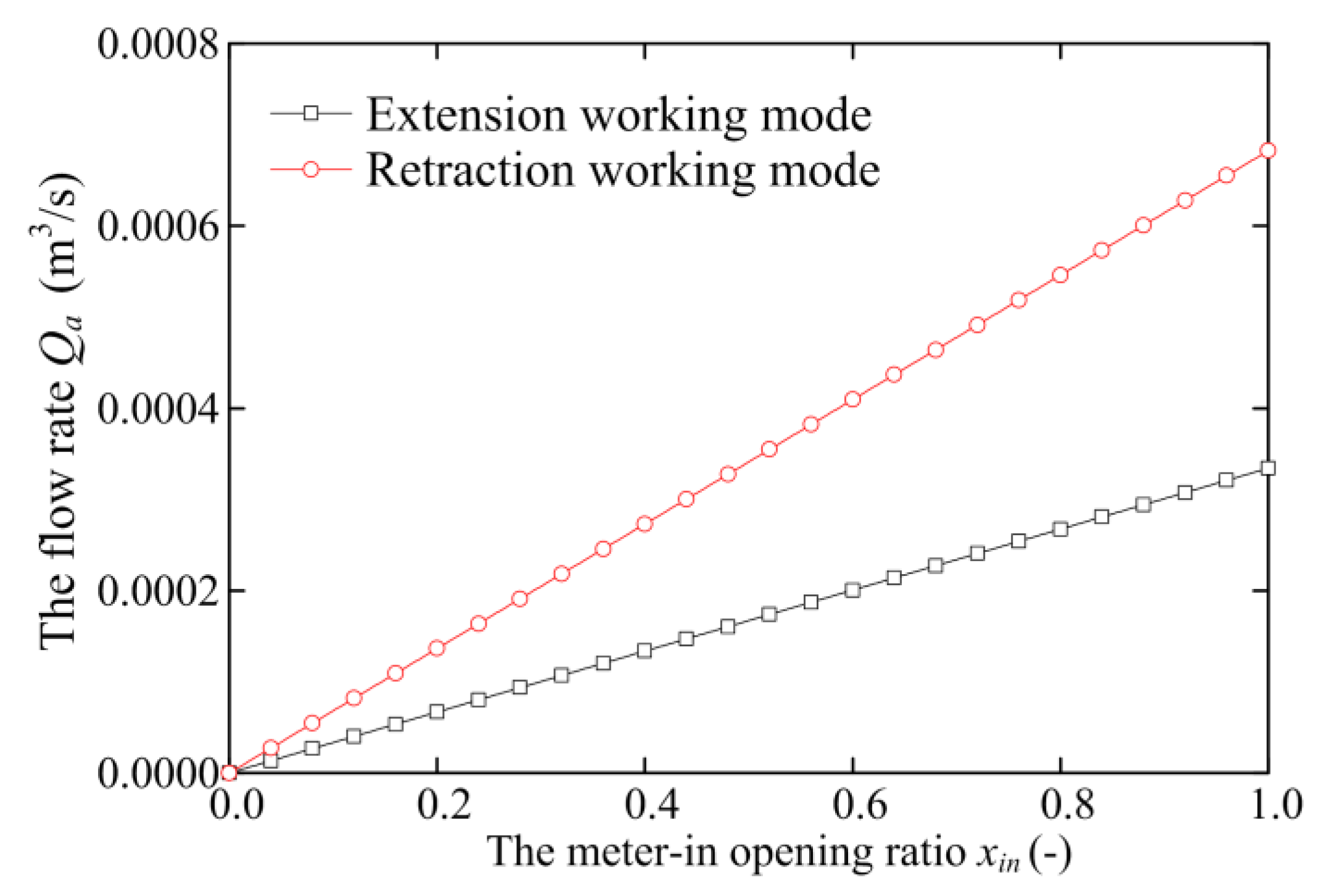
Pa are greater than 0, which is the gauge pressure, the flow rate Qa and Qb can be calculated by the continuity equations:
Q a = A a v
Q b = A b v
where Qa is the flow rate of the cylinder head chamber, Qb is the flow rate of the cylinder rod chamber.
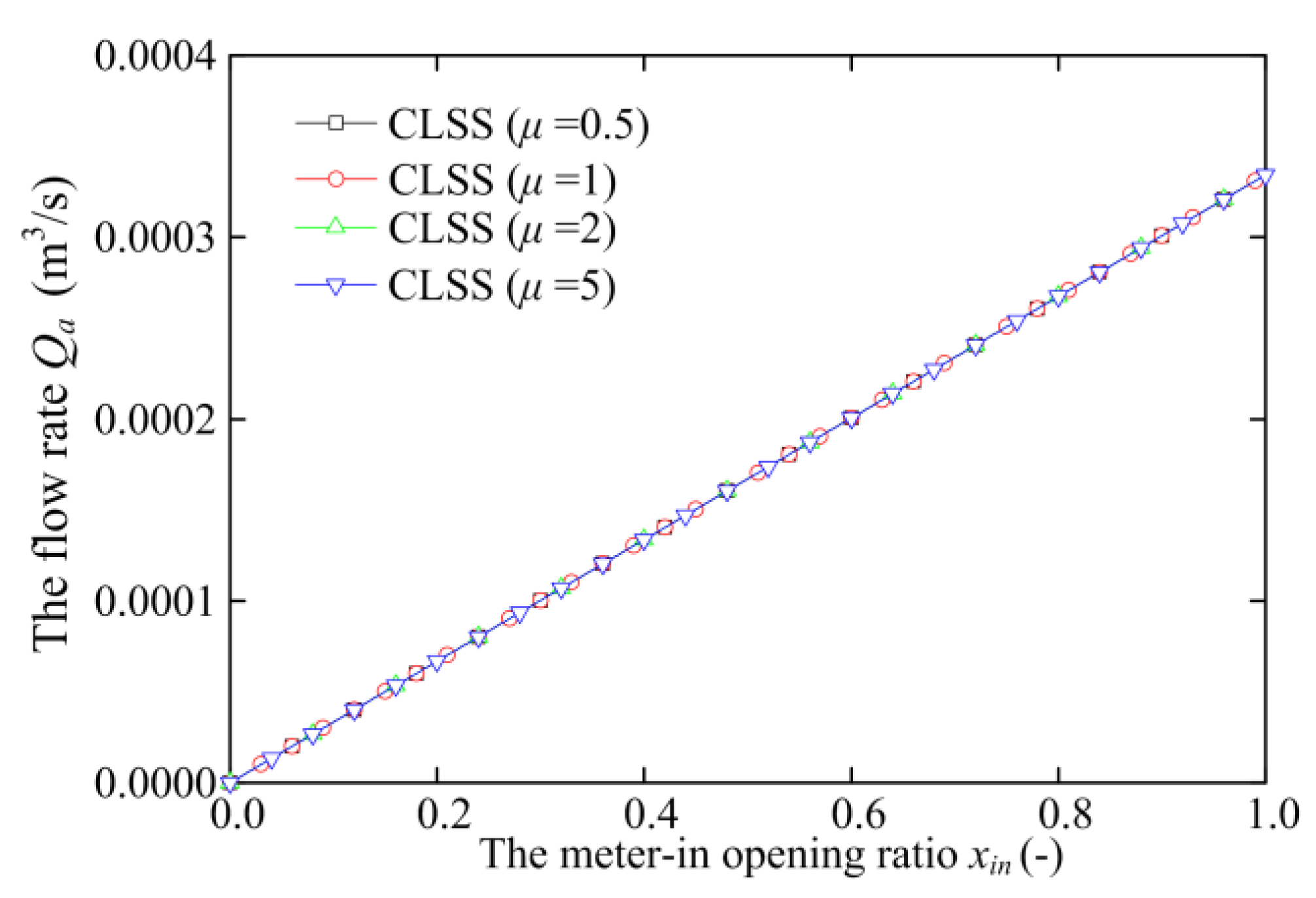
In the extension working mode with the eternal, active load as is shown in Figure 9a. From Equation (6), when the velocity v is increasing to a great value vmax, the inflow rate Qa of the cylinder head chamber will be increased to a great value Qamax. However, the output flow rate Qp of the pump is fixed. If the Qamax is greater than the output flow rate Qp of the pump, the cylinder head chamber will produce cavitation. As a result, the flow rate of the cylinder head chamber 
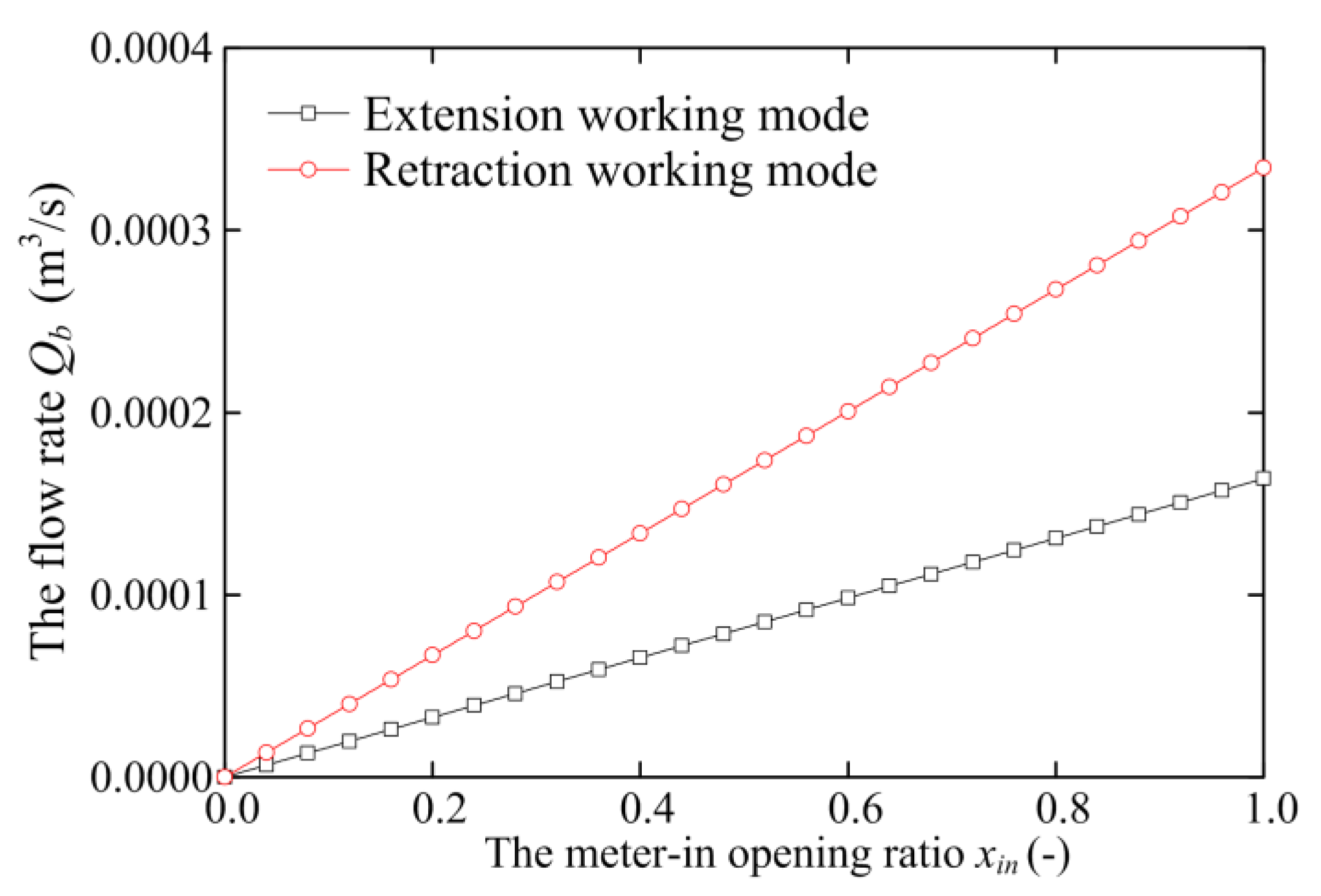
Qa cannot be calculated by Equation (6). However, 
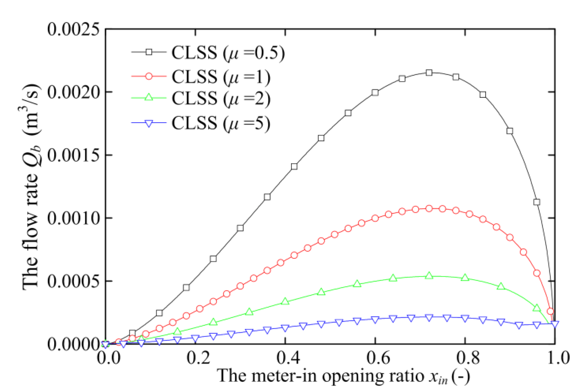
Qb is the outflow rate of the cylinder rod chamber, so it cannot produce cavitation, as a result, that the flow rate Qb can be calculated by Equation (7).
The retraction working mode with external active load is the same as the extension working mode with eternal, active load. As is shown in Figure 9b, when the external active load FL is greater than the maximum out force FPmax, the cylinder rod chamber will be produced the cavitation phenomenon, as a result, that the flow rate Qb cannot be calculated by Equation (7). Similarly, the flow rate Qa can be calculated by Equation (6).
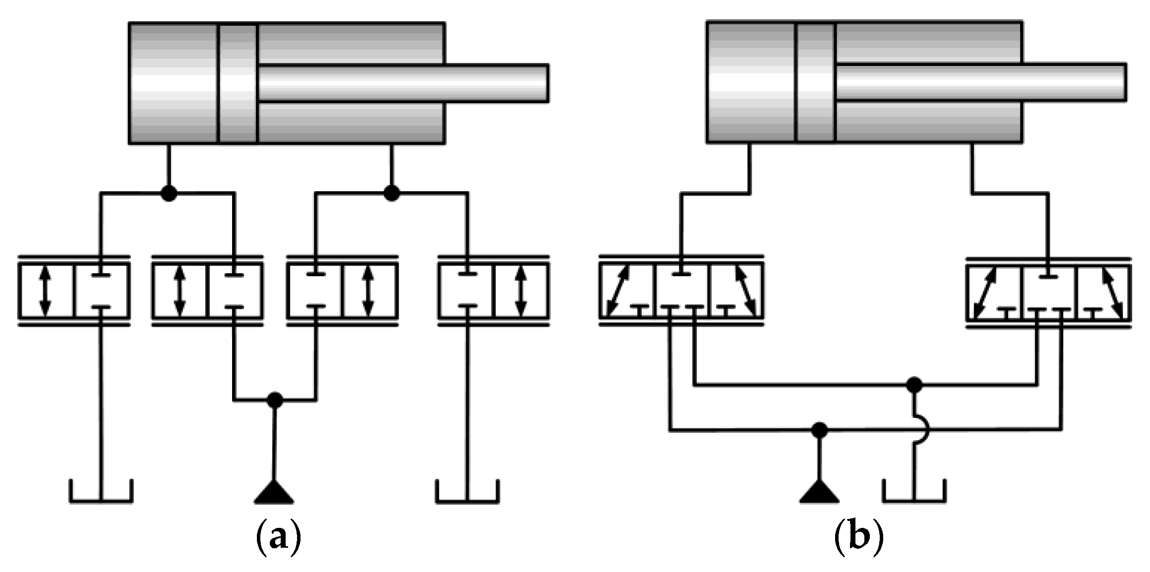
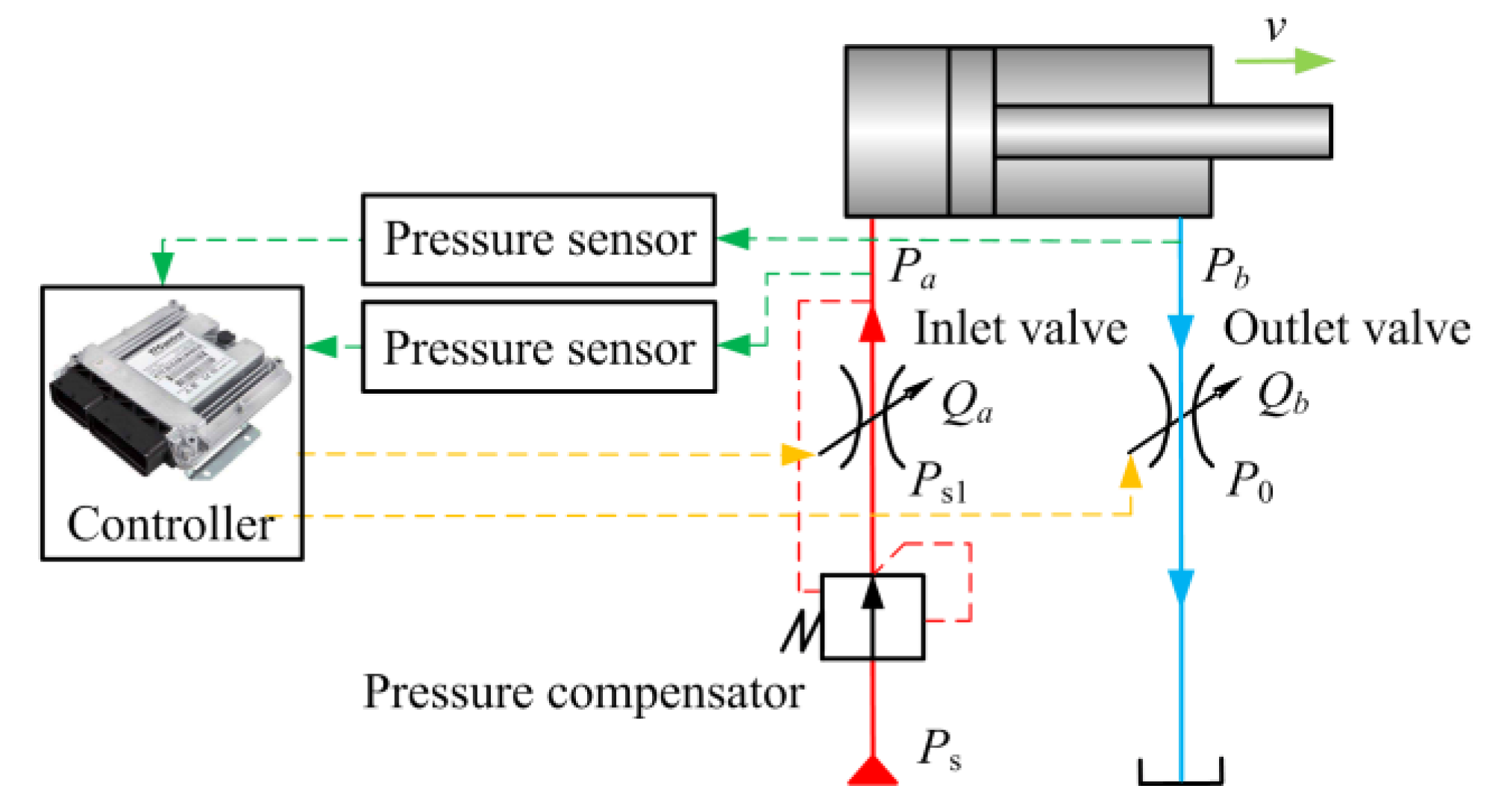
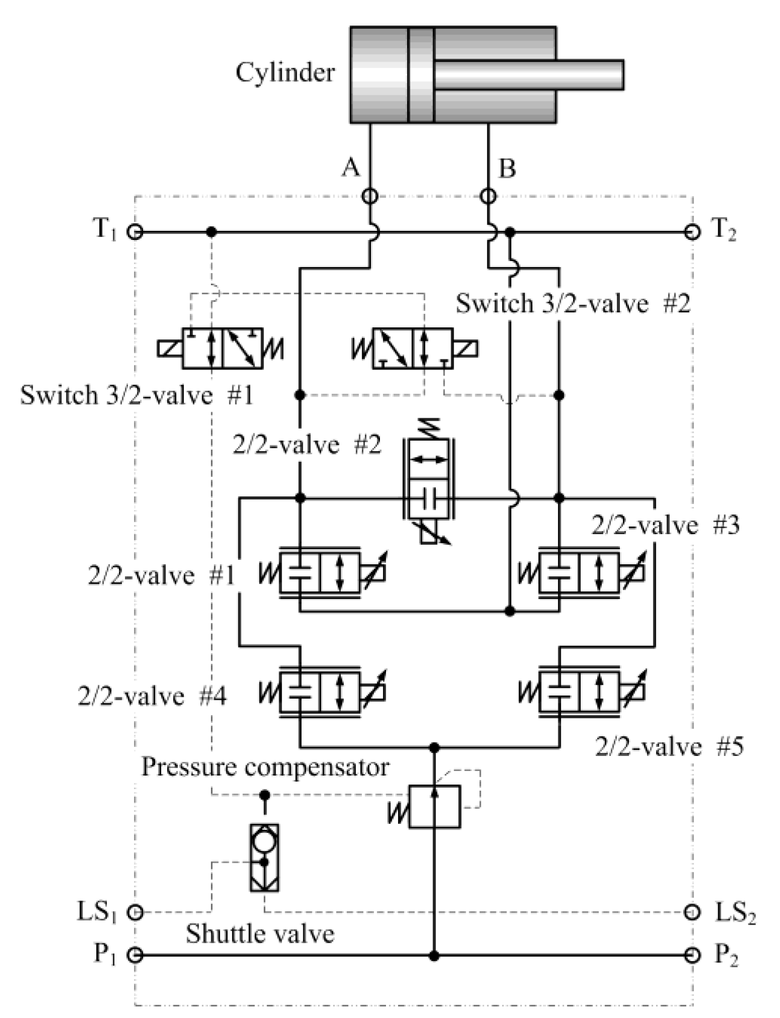
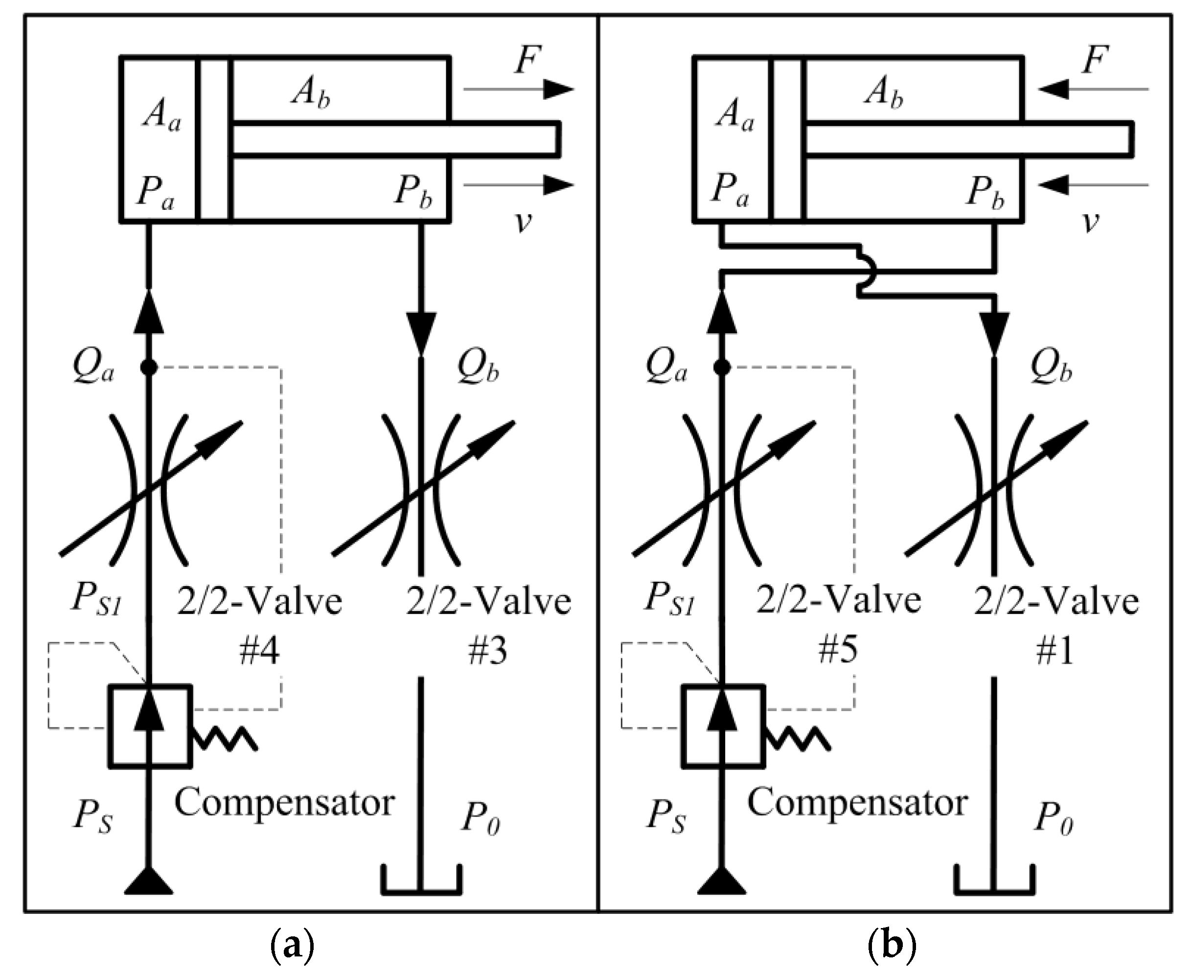
3.2. HPCIMS

In this section, the fluid compressibility and the dynamic effects are also ignored. HPCIMS, as is shown in Figure 6, can be simplified as is shown in Figure 10.
Figure 10a shows the simplified schematic of HPCIMS with the extension working mode, and it can be seen that the 2/2-valve #4 is controlling the inflow rate Qa of the cylinder head chamber, and the 2/2-valve #3 is controlling the outflow rate Qb of the cylinder rod chamber; as a result, the cylinder piston rod can be extended with the external active load FL. Figure 10b shows the simplified schematic of HPCIMS with the retraction working mode; it can be seen that the 2/2-valve #5 is controlling the inflow rate Qa of the cylinder rod chamber, and the 2/2-valve #1 is controlling the outflow rate Qb of the cylinder head chamber. As a result, the cylinder piston rod can be retracted with the external active load FL. Hence, take the extension working mode, for example, and it is similar to the retraction working mode.
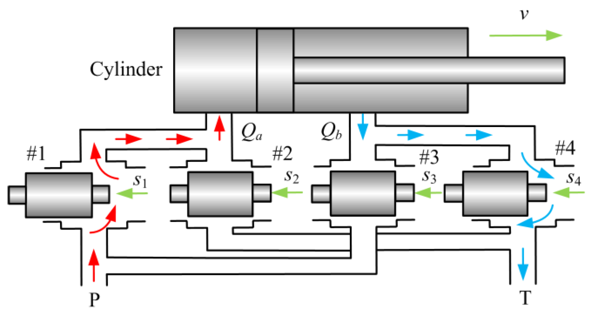
Assume the intrinsic parameters of the 2/2-valve #1, #2, #3, #4, and #5 are the same. As is shown in Figure 9a, flows in 2/2-valve #4 and 2/2-valve #3 can be expressed:
Q a = C d W x max x i n 2 ( P S 1 P a ) ρ
Q b = C d W x max x out 2 ( P b P 0 ) ρ
where Cd is the flow coefficient of the 2/2-valve, W is the area gradient of the 2/2-valve, xmax is the maximum displacement of the 2/2-valve sliding spool, xin is the opening ratio of 2/2-valve #4, xout is the opening ratio of 2/2-valve #3, PS1 is the outlet pressure of the compensator, P0 is the pressure of the tank, and ρ is the density of the hydraulic fluid.
If the external active load FL is increasing to a big value, the head chamber pressure Pa will be decreased to a negative value. If the head chamber pressure Pa is less than the vapor pressure Pc, the head chamber will produce cavitation.
Hence, if the head chamber pressure Pa is greater than the negative atmospheric pressure −Pat, which is the absolute pressure 0. Take the Equations (2) and (3) into derivation; the results can be obtained:
F L = P b A b P a A a
If the pressure Pa is less than negative atmospheric pressure −Pat, which is the absolute pressure 0, it equals −Pat, so the external active load FL can be expressed:
F L = P b A b + P a t A a
If the pressure Pa is greater than 0, flows in 2/2-valve #4 and 2/2-valve #3 with extension working mode can also be characterized by the following equations:
Q a = A a v
Q b = A b v
Taking the Equations (8), (9), (12) and (13) into derivation, and the results can be obtained:
Q a Q b = x i n P S 1 P a x o u t P b P 0 = A a A b
The differential pressure of 2/2-valve #4 is determined by the compensator, so it can be expressed:
Δ P = P S 1 P a
By defining μ = x i n x o u t , R = A a A b and the P0 is the pressure of tank can be assumed as 0. Squaring Equation (14) and rearranging the following expressions, the results are obtained:
P b = μ 2 R 2 Δ P
If the head chamber pressure Pa is greater than negative atmospheric pressure −Pat, which is the absolute pressure 0, take the Equations (10) and (16) into derivation, the pressure Pa can be obtained:
P a = μ 2 R 3 Δ P F L A a
If the head chamber pressure Pa is less than negative atmospheric pressure −Pat, which is the absolute pressure 0, the pressure Pa equals −Pat, and Pb can be expressed:
P b = F L P a t A a A b
If the cylinder head chamber pressure Pa is less than the vapor pressure Pc, the head chamber of the cylinder will produce cavitation. Hence, the pressure Pa must be greater than the vapor pressure 
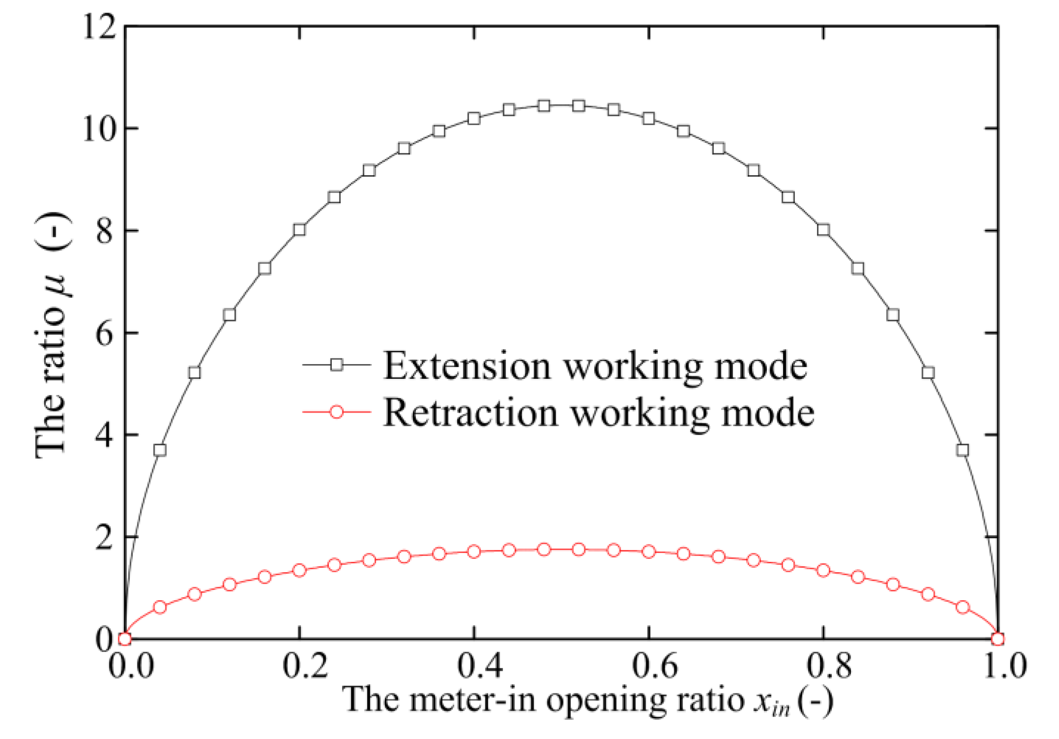
Pc. As the opening ratio xin of 2/2-valve #4 and the opening ratio xout of 2/2-valve #3 can be independently regulated, so the ratio μ is a variable parameter. The ratio μmin can be expressed:
μ min = ( F L + P c A a ) R 3 A a Δ P
Using the same method, the results of the retraction working mode can be obtained as follows:
P a = μ 2 R 2 Δ P
If the rod chamber pressure Pb is greater than the negative atmospheric pressure −Pat, the pressure Pb can be expressed:
P b = μ 2 R 3 Δ P F L A b
If the rod chamber pressure Pb is less than negative atmospheric pressure −Pat, the pressure Pb equals −Pat, the pressure Pa can be expressed:
P a = F L P a t A b A a
Similarly, if the cylinder rod chamber pressure Pb is less than the vapor pressure Pc, the rod chamber of the cylinder will produce cavitation. Hence, the pressure Pb must be greater than the vapor pressure Pc. Hence, the ratio μmin can also be expressed:
μ min = F L + P c A b A b Δ P R 3
In the extension working mode, the pressure Pa is the meter-in pressure, and the pressure Pb is the meter-out pressure. In the retraction working mode, the pressure Pa is the meter-out pressure, and the pressure Pb is the meter-in pressure.
Hence, the meter-in pressure Pa of extension working mode and the meter-in pressure Pb of retraction working mode can be calculated by the Equations (17) and (21). It is clear that the parameters R, Aa, Ab and ΔP are constant values. Hence, the meter-in pressure Pa of extension working mode and the meter-in pressure Pb of retraction working mode are related to the variable parameters μ and FL.
The meter-out pressure Pb, which is the cylinder head chamber pressure of extension working mode, can be calculated by Equations (16) and (18). It is clear that the pressure Pb is related to the variable parameter μ when the head chamber pressure Pa is greater than negative atmospheric pressure −Pat, and the pressure Pb is related to the variable parameter FL when the head chamber pressure Pa is less than negative atmospheric pressure −Pat. The meter-out pressure Pa of retraction working mode can be calculated by the Equations (20) and (22), it is clear the pressure Pa is related to the variable parameter μ when the rod chamber pressure Pb is greater than negative atmospheric pressure −Pat, and the pressure Pq is related to the variable parameter FL when the rod chamber pressure Pb is less than negative atmospheric pressure −Pat.
Because the meter-in valve opening ratio xin and meter-out opening ratio xout can be regulated independently, the ratio μ can be seen as an input variable parameter that can change the performance of HPCIMS. Equations (19) and (23) show that the minimum value of the ratio μ is related to the variable parameter FL.
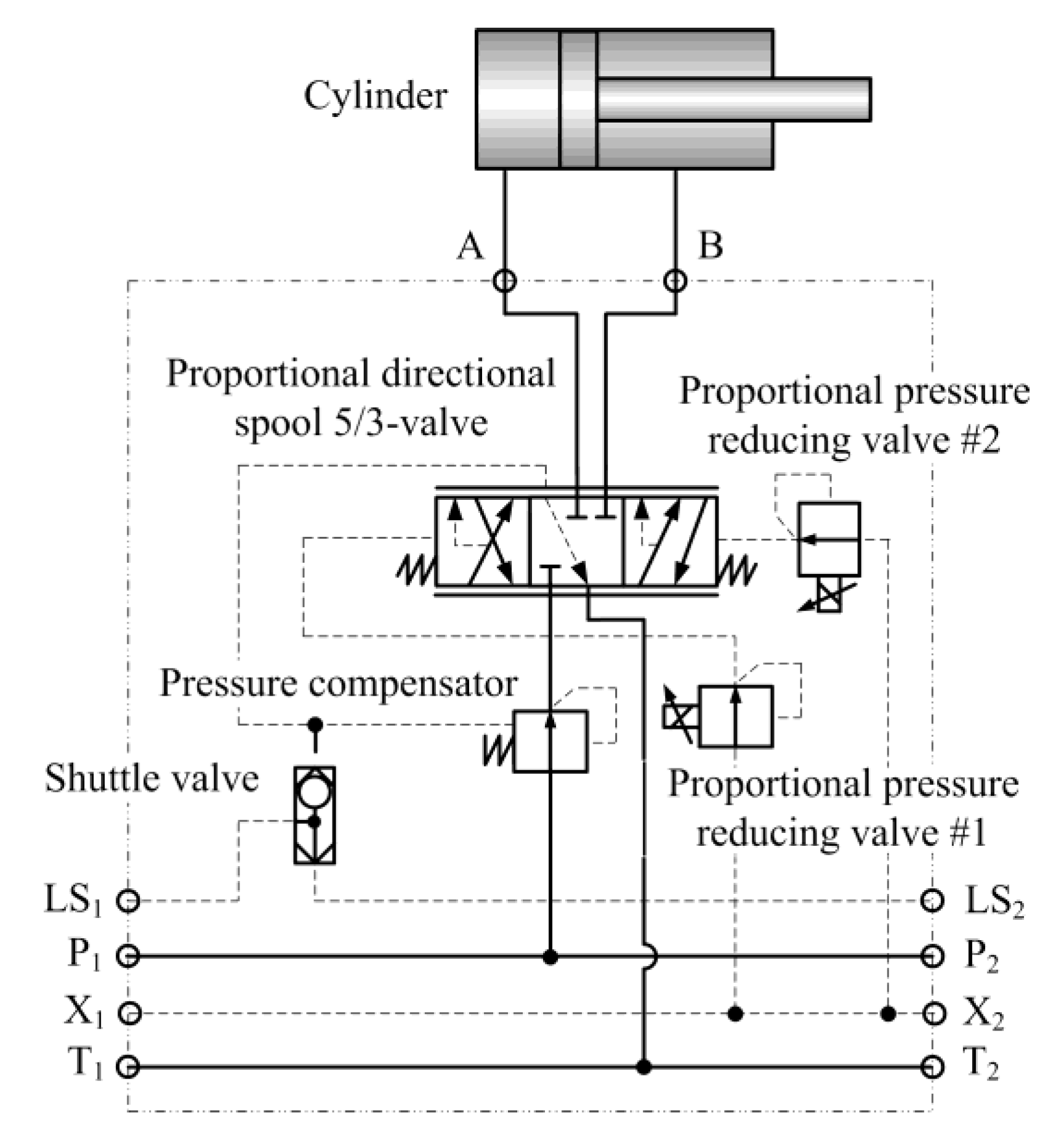
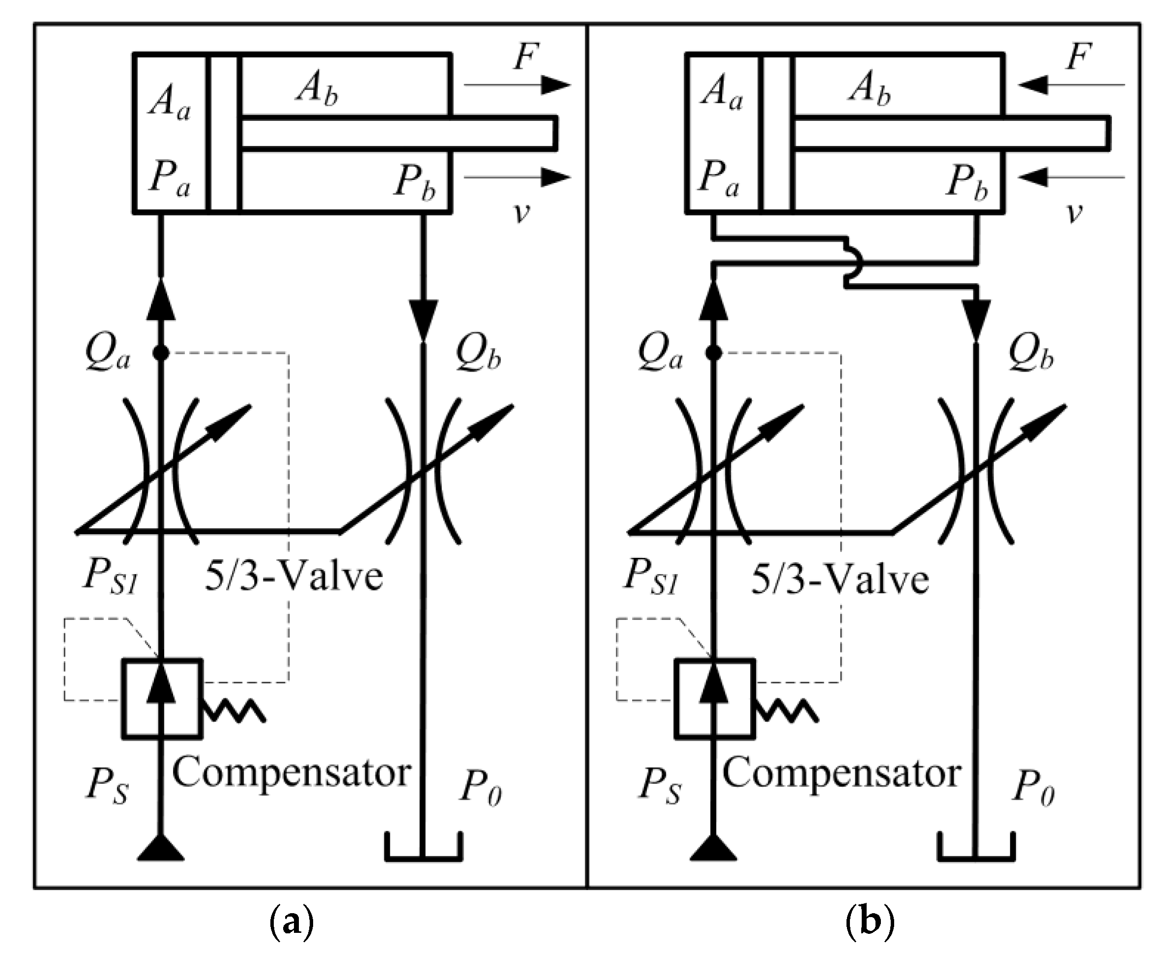
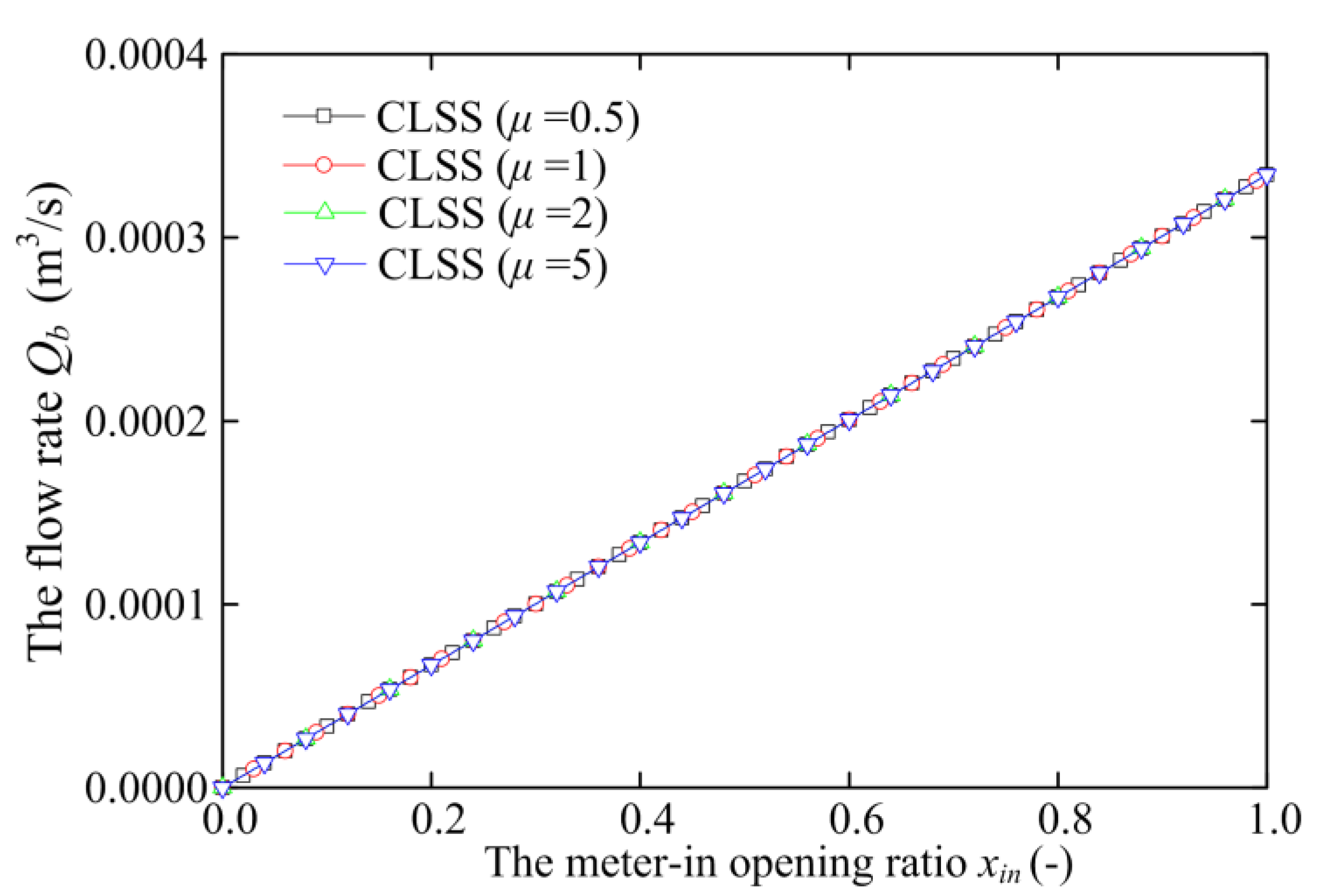
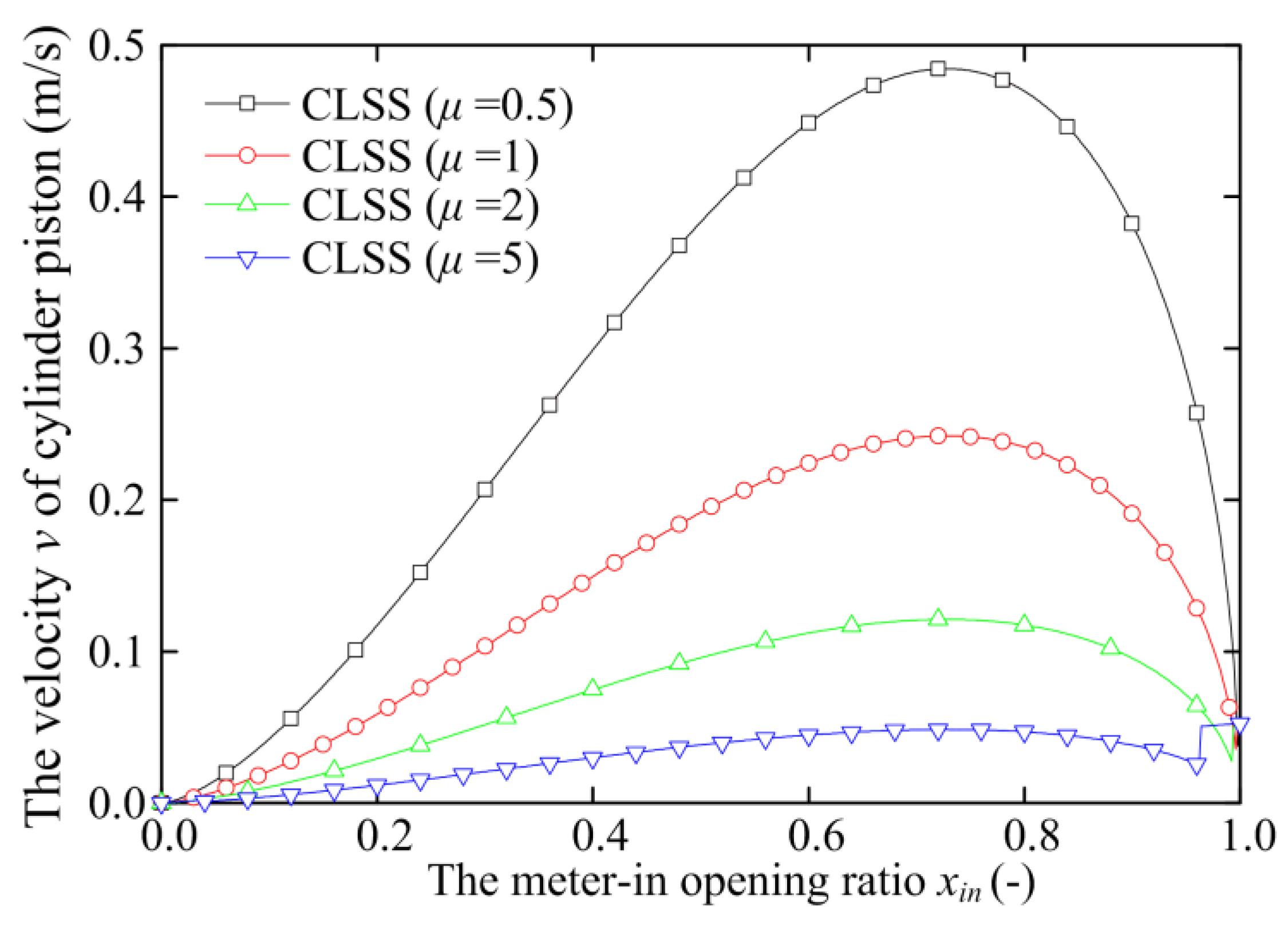
3.3. CLSS

CLSS, as is shown in Figure 7, can be simplified as is shown in Figure 11. Figure 11a shows the simplified schematic of CLSS with the extension working mode. It can be seen that the proportional directional spool 5/3-valve is controlling the inflow rate Qa of the cylinder head chamber and the outflow rate Qb of the cylinder rod chamber simultaneously, as a result, that the cylinder piston rod can be extended with the external active load FL. Figure 11b shows the simplified schematic of CLSS with the retraction working mode; it can be seen that the proportional directional spool 5/3-valve is controlling the inflow rate Qa of the cylinder rod chamber and the outflow rate Qb of the cylinder head chamber simultaneously, as a result, that the cylinder piston rod can be retracted with the external active load FL. Because the meter-in orifice and the meter-out orifice of the proportional directional spool 5/3-valve are mechanically connected, so the ratio μ between the meter-in orifice and meter-out orifice is a constant value. In the CLSS, the proportional directional spool 5/3-valve is symmetrical or asymmetrical, which is depending on the designer. The proportional directional symmetrical spool 5/3-valve is commonly used in the CLSS, which means the maximum spool displacements of the meter-in and meter-out are the same. As the mechanical connection of metering edges, so in this section, the proportional directional spool 5/3-valve the valve is symmetrical or asymmetric.
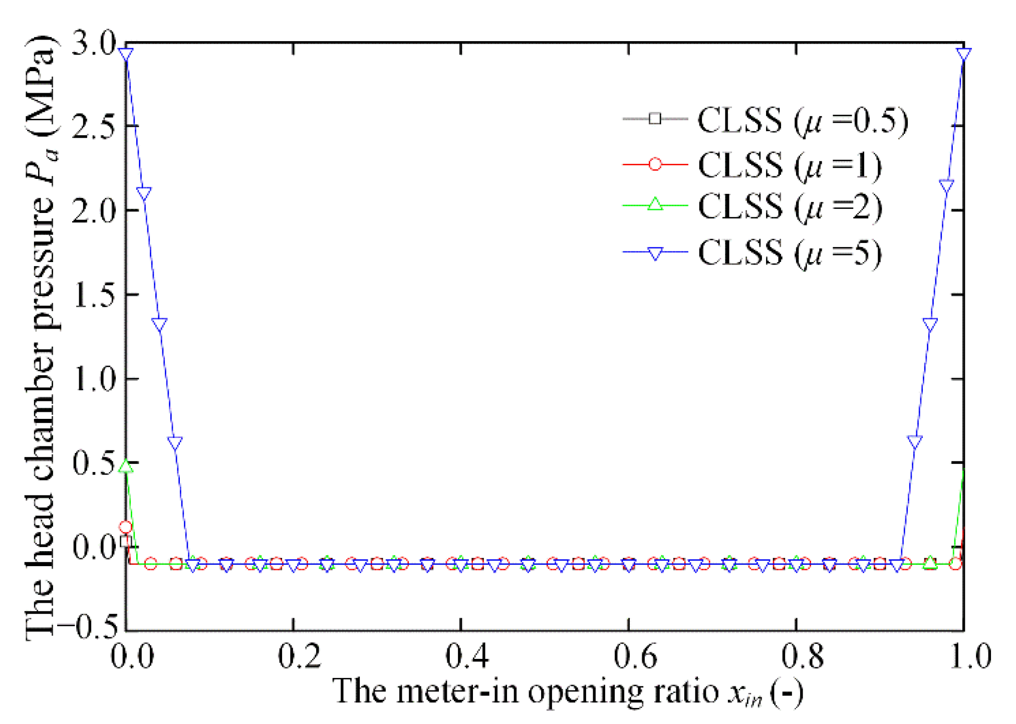
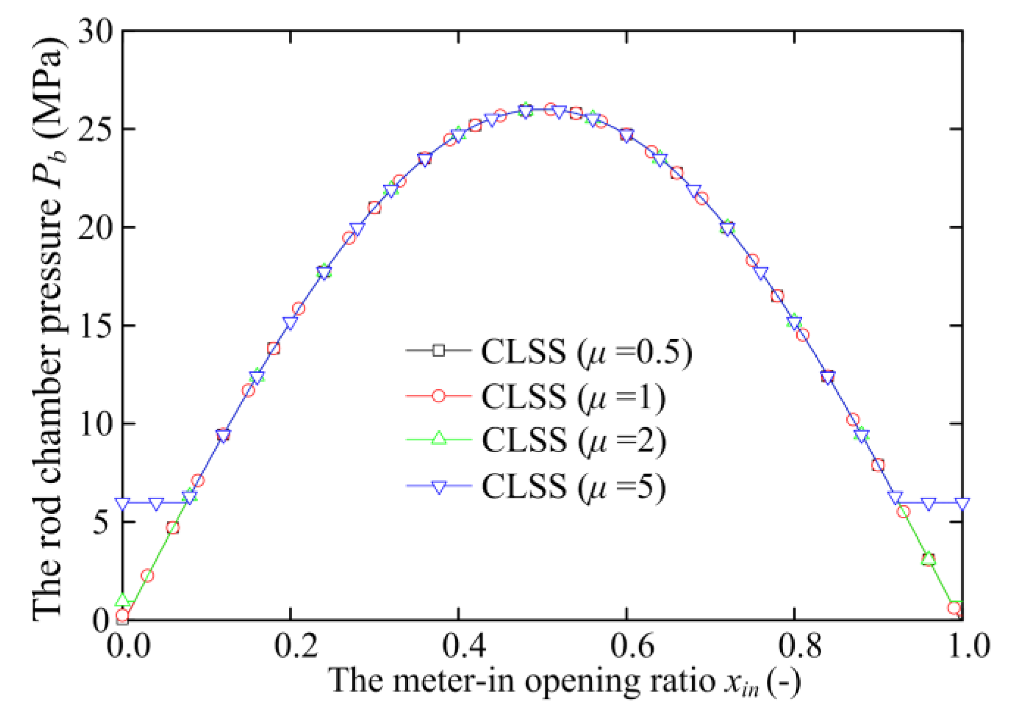
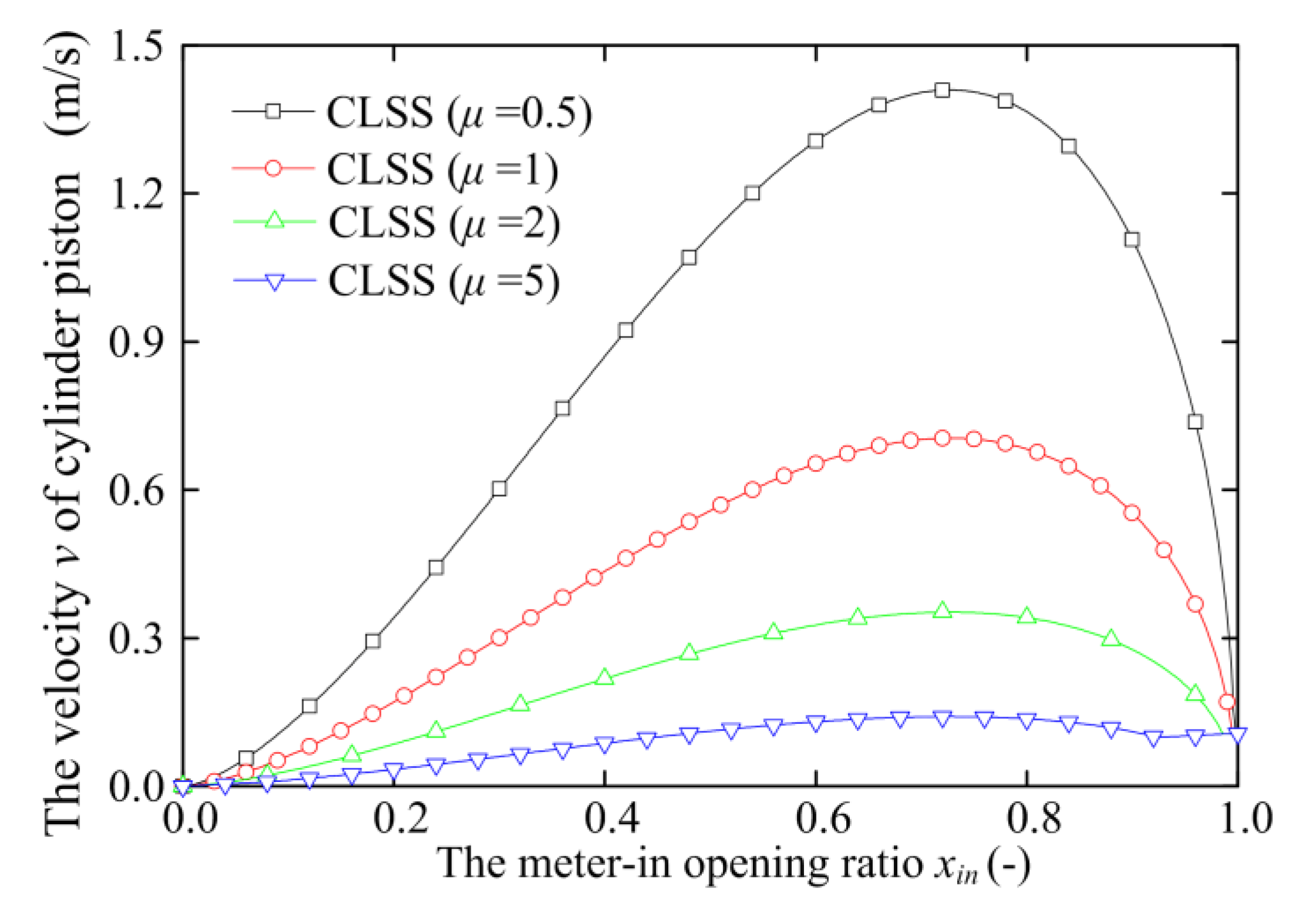
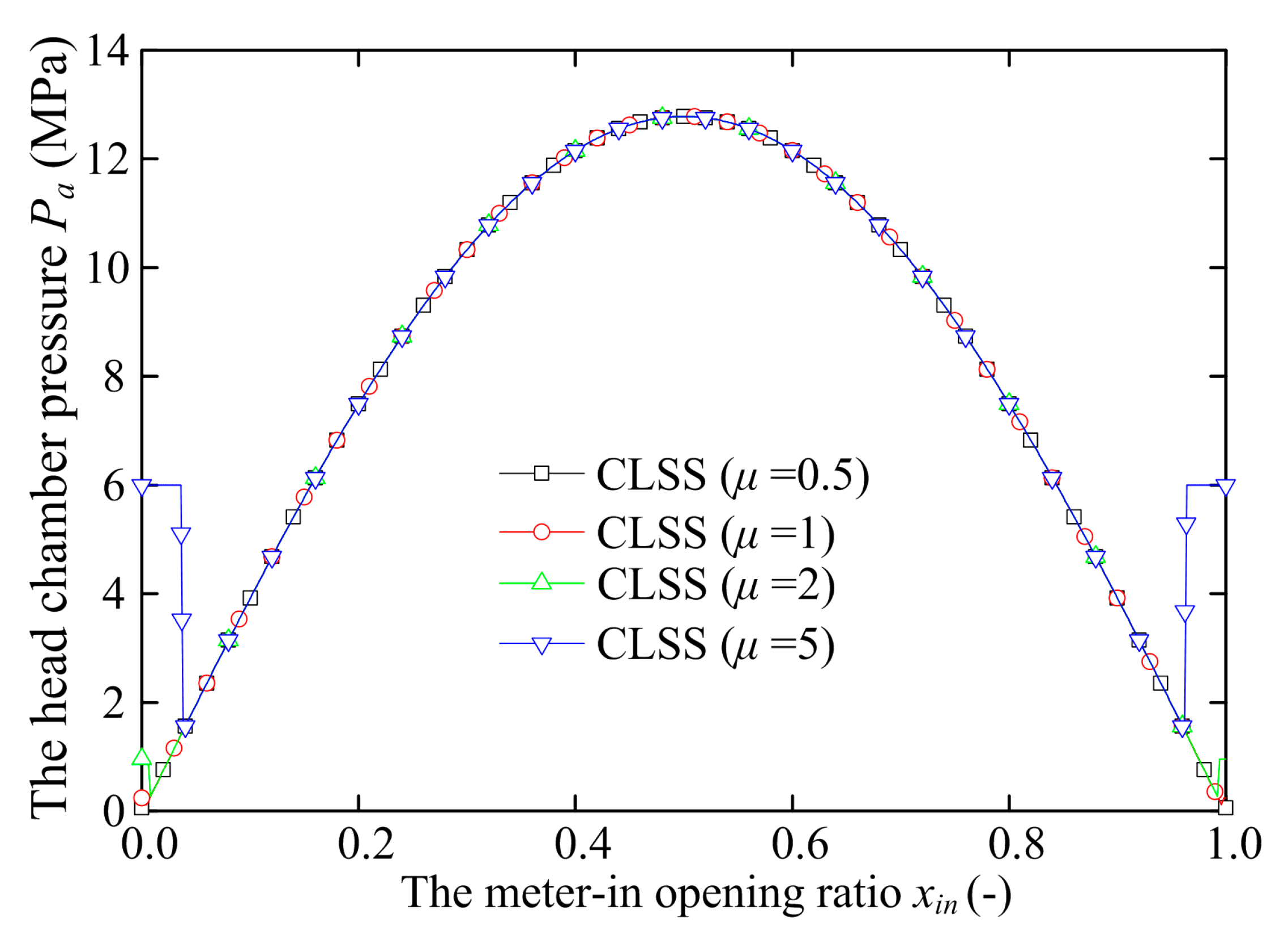
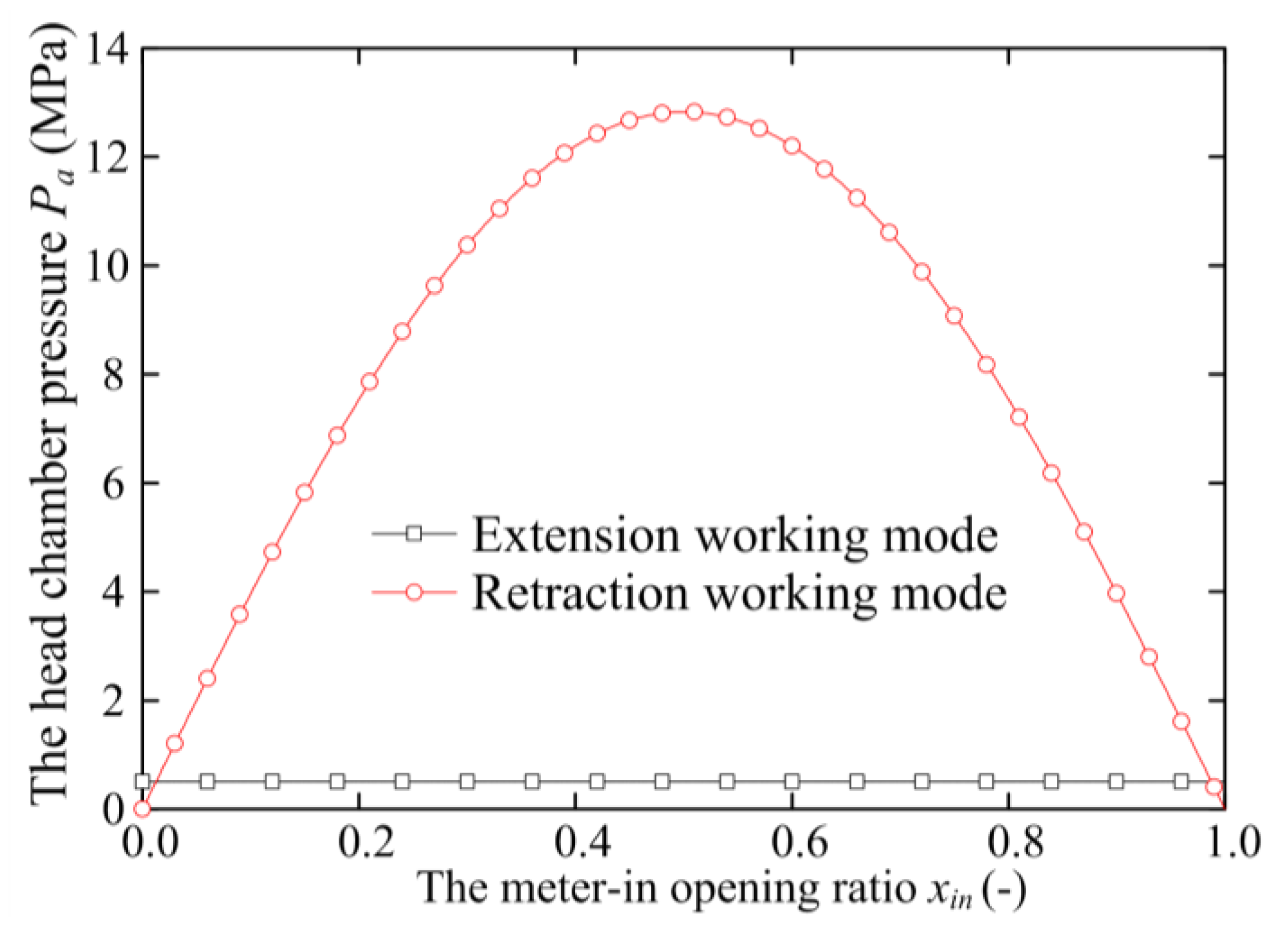
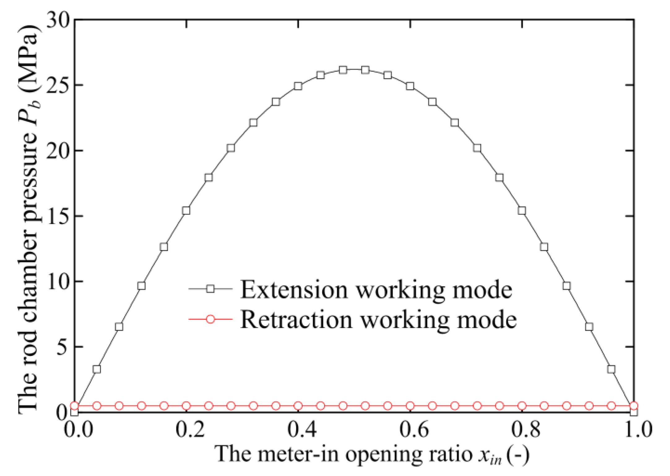
In the extension working mode, if the head chamber pressure Pa which is the meter-in pressure, is greater than the negative atmospheric pressure −Pat, the meter-in pressure Pa and the meter-out pressure Pb of the CLSS can be calculated by Equations (16) and (17). It is different from the HPCIMS; the ratio μ is fixed, which depends on the control valve. The velocity v of the cylinder piston rod can be calculated by Equation (13).
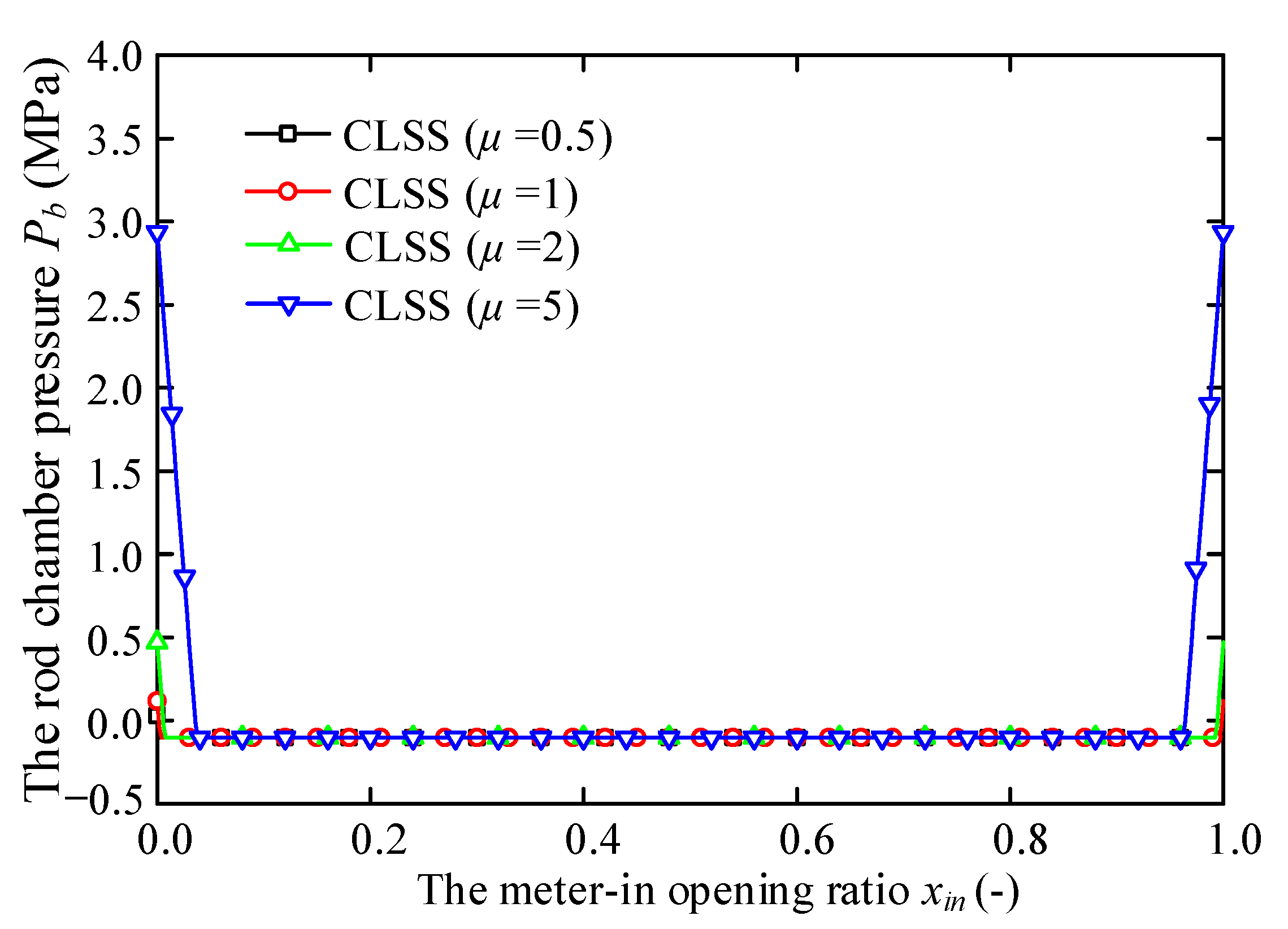
Moreover, if the head chamber pressure Pa is less than the negative atmospheric pressure −Pat, the pressure Pa equals −Pat, and Pb can also be calculated by Equation (18).
In the retraction working mode, if the rod chamber pressure Pb which is the meter-in pressure, is greater than the negative atmospheric pressure −Pat, the equations of the meter-out pressure Pa and the meter-in pressure Pb of the CLSS with retraction working mode can be calculated by Equations (20) and (21). It is different from the HPCIMS; the ratio μ is fixed, which is depending on the control valve. The velocity v of the cylinder piston rod can be calculated by Equation (12).
If the rod chamber pressure Pb is less than the negative atmospheric pressure −Pat, the pressure Pb equals −Pat, the pressure Pa can also be calculated by Equation (22).
The meter-in pressure Pa of extension working mode can be calculated by Equation (17). The meter-in pressure Pb of working retraction mode can be calculated by Equation (21). From the two equations, it is clear that the parameters μ, R, Aa, Ab, and ΔP are constant. Hence, the meter-in pressure Pa of extension working and the meter-in pressure Pb of retraction working mode are related to the external active load FL.
The meter-out pressure Pb with extension working mode can be calculated by Equations (16) and (18). From the two equations, it is clear that the pressure Pb is a constant when the meter-in pressure Pa is greater than the pressure −Pat, and the pressure Pb is related to the variable parameter FL when the meter-in pressure Pa is less than the pressure −Pat. The meter-out pressure Pa with retraction working mode can be calculated by Equations (20) and (22), it is clear that the pressure Pa is a constant when the meter-in pressure meter-in pressure Pb is greater than the pressure −Pat, and the pressure Pa is related to the variable parameter FL when the meter-in pressure meter-in pressure Pb is less than the pressure −Pat.

4. Cavitation Performance and Prevention Potential Analysis

4.1. Parameters Setting

In this section, the calculations are carried out using MATLAB software to preliminarily evaluate the cavitation performances of HPCIMS and CLSS. To secure the effective meter-in and meter-out valve opening ratios for preventing cavitation, it is necessary to compare the cavitation performance of HPCIMS and CLSS with extension working mode and retraction working mode. The parameters are setting as follows:
(1).
As listed in Table 1, all parameters of the two systems are standardized.
The head chamber area Aa and rod chamber area Ab are calculated by the cylinder-piston diameter and cylinder-rod diameter. The ratio R is calculated by the Aa and Ab. Assume that the vapor pressure Pc is 0.5 MPa, which is greater than the atmospheric pressure Pat.
(2).
The variable parameters of the two systems are listed in Table 2.
To obtain the general results, the external active load FL is increasing from 0 N to 40,000 N in a sine curve, as is shown in Figure 12. The ratio μ of HPCIMS is the μmin, which is calculated by the Equation (19) or (23). The ratio μ of CLSS is selected by four typical values 0.5, 1, 2 and 5. The meter-in valve opening ratio xin is increased proportionally from 0 to 1, and the meter-out valve opening ratio xout is calculated by the opening ratio xin and the ratio μ.

4.2. Analysis Results of CLSS

As is shown in Figure 7, the proportional directional spool 5/3-valve of the CLSS is the main control valve, which is symmetric or asymmetric. If the main control valve is symmetric, the ratio μ equals 1. In most cases, the main control valve is asymmetric, so assume that the ratio μ equals four typical values 0.5, 1, 2, and 5. To obtain the general results, the extension working mode and retraction working mode are analyzed in this section.
Taking the Equations (13), (16)–(18) into calculations of CLSS with extension working mode, the analysis results can be seen in Figure 13, Figure 14, Figure 15, Figure 16 and Figure 17.
Figure 13 shows that when the external active load FL is increasing at a certain value, the head chamber pressure Pa is below gauge pressure 0 MPa when the meter-in opening ratio xin is generally from 0.1 to 0.9 no matter what the ratio μ is 0.5, 1, 2 and 5, and the minimum value of the ratio μ is −0.101 MPa which is the negative atmosphere pressure. Hence, it will be produced the cavitation phenomenon in the head chamber. Figure 14 shows that the rod chamber pressure Pb is changing, which is depending on the external active load FL. Figure 15 shows that the flow rate Qa of the cylinder head chamber is proportional to the meter-in opening ratio xin because of the existence of the pressure compensator.
From Figure 16 and Figure 17, it is clear that the flow rate Qb of the cylinder rod chamber and the velocity v of the cylinder piston are changing nonlinearly with increasing of the meter-in opening ratio xin, and the values of the Qb and v are increasing-with-increasing of the ratio μ. Compared with Figure 15 and Figure 16, the flow rate Qa and Qb are not satisfied with the continuity equations. It is not desired that the velocity v of the cylinder piston of the CLSS with extension working mode is nonlinear.
Similarly, taking the Equations (13), (16)–(18) into calculations of CLSS with retraction working mode, the analysis results can be seen in Figure 18, Figure 19, Figure 20, Figure 21 and Figure 22.
It is different from the extension working mode, the cylinder head chamber is the meter-out chamber, and the cylinder rod chamber is the meter-in chamber in the retraction working mode. Figure 18 shows that in the retraction working mode, the head chamber pressure Pa is changing as the variations of external active load FL. Figure 19 shows that the rod chamber pressure Pb is below gauge pressure 0 MPa when the meter-in opening ratio xin is generally from 0.05 to 0.95 no matter what the ratio μ is 0.5, 1, 2 and 5, and the minimum value of the ratio μ is −0.101 MPa. Hence, it will produce the cavitation phenomenon in the rod chamber. Figure 21 shows that the flow rate Qb of the cylinder rod chamber is proportional to the meter-in opening ratio xin because of the existence of the pressure compensator. Figure 20 and Figure 22 show that the flow rate Qa of the cylinder head chamber and the velocity v of the cylinder piston are changing nonlinearly with an increase of the meter-in opening ratio xin. Compared with Figure 15 and Figure 16, the flow rate Qa and Qb are also not satisfied with the continuity equations. It is not desired that the velocity v of the cylinder piston of the CLSS with retraction working mode is nonlinear.
As a result, in the extension working mode or retraction working mode of CLSS, the meter-in chamber pressure of the cylinder will be below gauge pressure 0 MPa when the external active load FL is increasing at a certain value, so will be produced the cavitation phenomenon. The velocity v of the cylinder piston in the extension working mode or retraction working mode of CLSS is nonlinear to the meter-in opening ratio xin or the meter-out opening ratio xout when the meter-in chamber pressure is below gauge pressure 0 MPa, and it is not desired for the hydraulic system. Because the ratio μ is selected by four typical values 0.5, 1, 2, and 5, the meter-out opening ratio xout is proportional to the meter-in opening ratio xin.

4.3. Analysis Results of HPCIMS

In the HPCIMS, there are two control valves that can independently control the inflow rate and outflow rate of the cylinder chambers, so the ratio μ, which is the ratio of the meter-in opening ratio xin and the meter-out opening ratio xout is changed, and it can be calculated by the Equation (19) or (23) for preventing cavitation phenomenon. Taking the Equations (12)–(23) into calculations of HPCIMS (hydromechanical pressure compensation independent metering system) with extension working mode and retraction working mode, the analysis results can be seen in Figure 23, Figure 24, Figure 25, Figure 26, Figure 27 and Figure 28.
Figure 23 and Figure 24 show that the head chamber pressure Pa of HPCIMS with extension working mode and the rod chamber pressure Pb of HPCIMS with retraction working mode are stable nearby the vapor pressure Pc, which is setting as 0.5 MPa, and the head chamber pressure Pa of HPCIMS with retraction working mode and the rod chamber pressure Pb of HPCIMS with extension working mode is increasing by the external active load FL.
As is shown in Figure 25 and Figure 26, the flow rate Qa and Qb of HPCIMS with two working modes are proportional to the meter-in opening ratio xin. Compared with Figure 25 and Figure 26, the flow rate Qa and Qb are satisfied with the continuity equations.
In Figure 27, it is clear that the velocity v of the cylinder piston of HPCIMS with two working modes is proportional to the meter-in opening ratio xin. It is different from the CLSS, as is shown in Figure 28, the ratio μ of HPCIMS is changing with the meter-in opening ratio xin.
As a result, the cavitation phenomenon in the meter-in chamber of CLSS when the external active load is inevitable. However, in HPCIMS, it can be preventing the cavitation phenomenon by changing the ratio μ. To compare with the CLSS, the HPCIMS has a greater advantage for preventing cavitation phenomenon with external active load.

5. Conclusions

The working principle of HPCIMS and its cavitation performances was investigated in this paper. In the hydraulic system, the cavitation phenomenon occurs when the pressure falls below the vapor pressure. Compared with the CLSS, the meter-in opening ratio xin and meter-out opening ratio xout of the HPCIMS can be regulated independently. When changing the ratio μ of the meter-in opening ratio xin and meter-out opening ratio xout can prevent cavitation phenomenon according to the derived equations. The cavitation performances of the CLSS and HPCIMS are compared by the calculations of the above equations.
In the CLSS with two working modes, the meter-in pressure will fall below gauge pressure 0 MPa when the external active load FL is increasing at a certain value. In HPCIMS with two working modes, the meter-in pressure can be kept as a fixed value which is greater than or equal to vapor pressure Pc by changing the ratio μ.
When the external active load FL is increasing at a certain value, the meter-in flow rate of CLSS is linear, the meter-out flow rate of CLSS is nonlinear, both the meter-in flow rate and meter-out flow rate of CLSS are not satisfied with the continuity equations. In HPCIMS, both the meter-in flow rate and meter-out flow rate are linear and are satisfied with the continuity equations. The velocity v of the cylinder piston of the CLSS with two working modes are nonlinear. However, the velocity v of the cylinder piston of HPCIMS with two working modes is proportional to the meter-in opening ratio xin.
Hence, the cavitation phenomenon can be prevented in HPCIMS with the external active load by changing the ratio μ according to the derived equations. Moreover, it can be obtained the linear velocity v of the cylinder piston with the meter-in opening ratio xin.
In this study, the dynamic effects and system stability are ignored, so the analysis results have a certain limitation. The results are considered a reference for designing the software and hardware of HPCIMS. Moreover, the cavitation phenomenon preventing the control strategy of the HPCIMS yet requires further research.

Author Contributions

Investigation, K.L. and S.K.; methodology, S.K. and H.Q.; validation, K.L. and H.Q.; data curation, H.Q. and C.Y.; writing—original draft preparation, K.L.; writing—review and editing, S.K. and H.Q.; writing—analysis and conclusion, K.L., S.K. and H.Q.; supervision, S.K. and C.Y.; funding acquisition, K.L., S.K. and C.Y. All authors have read and agreed to the published version of the manuscript.

Funding

This research was supported by the Youth program of the National Natural Science Foundation of China (Grant No. 51805228), Natural Science Fund for Colleges and Universities in Jiangsu Province (Grant No. 20KJB580005) and the Social Development Project of Jiangsu Key Research and Development (Grant No. BE2018641).

Institutional Review Board Statement

Not applicable.

Informed Consent Statement

Not applicable.

Data Availability Statement

The data presented in this study are available on request from the corresponding author.

Conflicts of Interest

The authors declared no conflicts of interest.

References

  1. Ding, R.; Xu, B.; Zhang, J.; Cheng, M. Bumpless mode switch of independent metering fluid power system for mobile machinery. Autom. Constr. 2016, 68, 52–64. [Google Scholar] [CrossRef]
  2. Shi, J.; Quan, L.; Zhang, X.; Xiong, X. Electro-hydraulic velocity and position control based on independent metering valve control in mobile construction equipment. Autom. Constr. 2018, 94, 73–84. [Google Scholar] [CrossRef]
  3. Yuan, Q.; Lew, J.Y. Modeling and Control of Two Stage Twin Spool Servo-Valve for Energy-Saving. In Proceedings of the American Control Conference, Portland, OR, USA, 8–10 June 2005; pp. 4363–4368. [Google Scholar]
  4. Hu, H.; Zhang, Q. Realization of programmable control using a set of individually controlled electrohydraulic valves. Int. J. Fluid Power 2002, 3, 29–34. [Google Scholar] [CrossRef]
  5. Edge, K. The control of fluid power systems-responding to the challenges. Proc. Inst. Mech. Eng. Part I J. Syst. Control Eng. 1997, 211, 91–110. [Google Scholar] [CrossRef]
  6. Abuowdaa, K.; Okhotnikov, I.; Noroozi, S.; Godfrey, P.; Dupac, M. A review of electrohydraulic independent metering technology. ISA Trans. 2020, 98, 364–381. [Google Scholar] [CrossRef] [PubMed]
  7. Jansson, A.; Palmberg, J.O. Separate Controls of Meter-in and Meter-out Orifices in Mobile Hyraulic Systems. SAE Tech. Pap. 1990, 99, 377–383. [Google Scholar]
  8. Liu, K.; Gao, Y.; Tu, Z. Energy saving potential of load sensing system with hydro-mechanical pressure compensation and independent metering. Int. J. Fluid Power 2016, 17, 173–186. [Google Scholar] [CrossRef]
  9. Liu, S.; Yao, B. Energy-saving control of single-rod hydraulic cylinders with programmable valves and improved working mode selection. SAE Tech. Pap. 2002, 111, 51–61. [Google Scholar]
  10. Eriksson, B.; Palmberg, J.O. Individual metering fluid power systems: Challenges and opportunities. Proc. Inst. Mech. Eng. Part I J. Syst. Control Eng. 2011, 225, 196–211. [Google Scholar] [CrossRef]
  11. Yao, B.; DeBoer, C. Energy-saving Adaptive Robust Motion Control of Single-rod Hydraulic Cylinders with Programmable Valves. In Proceedings of the American Control Conference, Anchorage, AK, USA, 8–10 May 2002; pp. 4819–4824. [Google Scholar]
  12. Liu, S.; Yao, B. Automated onboard modeling of cartridge valve flow mapping. Mechatron. IEEE/ASME Trans. 2006, 11, 381–388. [Google Scholar]
  13. Liu, S.; Yao, B. Coordinate control of energy saving programmable valves. IEEE Trans. on Contr. Syst. Tech. 2008, 16, 34–45. [Google Scholar] [CrossRef]
  14. Hu, H.; Zhang, Q. Multi-function realization using an integrated programmable E/H control valve. Appl. Eng. Agric. 2003, 11, 283–290. [Google Scholar]
  15. Hu, H.; Zhang, Q. Development of a programmable E/H valve with a hybrid control algorithm. Applied SAE Tech. Pap. 2002, 111, 413–419. [Google Scholar]
  16. Choi, K.; Seo, J.; Nam, Y.; Kyeong, U.K. Energy-saving in excavators with application of independent metering valve. J. Mech. Sci. Technol. 2015, 29, 387–395. [Google Scholar] [CrossRef]
  17. Xu, B.; Ding, R.; Zhang, J.; Cheng, M.; Sun, T. Pump/valves coordinate control of the independent metering system for mobile machinery. Autom. Constr. 2015, 57, 98–111. [Google Scholar] [CrossRef]
  18. Ding, R.; Xu, B.; Zhang, J.; Cheng, M. Self-tuning pressure-feedback control by pole placement for vibration reduction of excavator with independent metering fluid power system. Mech. Syst. Signal Process. 2017, 92, 86–106. [Google Scholar] [CrossRef]
  19. Sitte, A.; Weber, J. Structural design of independent metering control systems. In 11th Scandinavian International Conference on Fluid Power; Linköping University Electronic Press: Linköping, Sweden, 2002; pp. 261–270. [Google Scholar]
  20. Liu, K.; Gao, Y.; Tu, Z.; Lin, P. Energy-saving analysis of the independent metering system with pressure compensation for excavator’s manipulator. Proc. Inst. Mech. Eng. Part I J. Syst. Control Eng. 2016, 230, 905–920. [Google Scholar] [CrossRef]
  21. Cucit, V.; Burlon, F.; Fenu, G.; Furlanetto, R.; Pellegrino, F.A.; Simonato, M. A control system for preventing cavitation of centrifugal pumps. Energy Procedia 2018, 148, 242–249. [Google Scholar] [CrossRef]
  22. Wang, W.; Li, Y.; Osman, M.K.; Yuan, S.; Zhang, B.; Liu, J. Multi-Condition Optimization of Cavitation Performance on a Double-Suction Centrifugal Pump Based on ANN and NSGA-II. Processes 2020, 8, 1124. [Google Scholar] [CrossRef]
  23. Kang, D.; Yokota, K. Analytical study of cavitation surge in a hydraulic system. J. Fluid Eng. 2014, 136, 101103-1–101103-10. [Google Scholar] [CrossRef]
  24. Zhang, J.; Duan, B.; Jiang, J.; Zhi, H. Study on the effect of the pressure characteristics of the cone throttle on the cavitation. J. Eng. 2019, 2019, 319–322. [Google Scholar] [CrossRef]
  25. Jiang, W.; Chang, J. Cavitation Performance of Hydraulic Turbines in the Three Gorges Reservoir with Consideration of Influence of Total Phosphorus Pollution. J. Fluid Eng. 2016, 138, 081301. [Google Scholar] [CrossRef]
  26. Merritt, H.E. Hydraulic Control Systems; John Wiley & Sons: New York, NY, USA, 1967; pp. 45–46. [Google Scholar]
Figure 1. Principle of a spool valve controls a cylinder.
Processes 09 00255 g001
Figure 2. Principle of an independent metering control system.
Processes 09 00255 g002
Figure 3. Two typical kinds of hydraulic system layouts. (a) Four 2/2-valves (b) two 3/3-valves.
Processes 09 00255 g003
Figure 4. Electro-hydraulic pressure compensation method.
Processes 09 00255 g004
Figure 5. Hydromechanical pressure compensation method.
Processes 09 00255 g005
Figure 6. Hydromechanical pressure compensation independent metering control block controls a cylinder.
Processes 09 00255 g006
Figure 7. Conventional load sensing control block controls a cylinder.
Processes 09 00255 g007
Figure 8. The hydraulic system pressure area division.
Processes 09 00255 g008
Figure 9. Two working modes with external active load.
Processes 09 00255 g009
Figure 10. Simplified schematic of hydromechanical pressure compensation independent metering system (HPCIMS) with two working modes. (a) Extension working mode, (b) retraction working mode.
Processes 09 00255 g010
Figure 11. Simplified schematic of conventional load sensing system (CLSS) with two working modes. (a) Extension working mode, (b) retraction working mode.
Processes 09 00255 g011
Figure 12. The external active load FL of the two systems.
Processes 09 00255 g012
Figure 13. The head chamber pressure Pa of CLSS with extension working mode.
Processes 09 00255 g013
Figure 14. The rod chamber pressure Pb of CLSS with extension working mode.
Processes 09 00255 g014
Figure 15. The flow rate Qa of the cylinder head chamber of CLSS with extension working mode.
Processes 09 00255 g015
Figure 16. The flow rate Qb of the cylinder rod chamber of CLSS with extension working mode.
Processes 09 00255 g016
Figure 17. The velocity v of the cylinder piston of CLSS with extension working mode.
Processes 09 00255 g017
Figure 18. The head chamber pressure Pa of CLSS with retraction working mode.
Processes 09 00255 g018
Figure 19. The rod chamber pressure Pb of CLSS with retraction working mode.
Processes 09 00255 g019
Figure 20. The flow rate Qa of the cylinder head chamber of CLSS with retraction working mode.
Processes 09 00255 g020
Figure 21. The flow rate Qb of the cylinder rod chamber of CLSS with retraction working mode.
Processes 09 00255 g021
Figure 22. The velocity v of the cylinder piston of CLSS with retraction working mode.
Processes 09 00255 g022
Figure 23. The variations of the head chamber pressure Pa of HPCIMS.
Processes 09 00255 g023
Figure 24. The variations of the rod chamber pressure Pb of HPCIMS.
Processes 09 00255 g024
Figure 25. The variations of the flow rate Qa of the cylinder head chamber of HPCIMS.
Processes 09 00255 g025
Figure 26. The variations of the flow rate Qb of the cylinder rod chamber of HPCIMS.
Processes 09 00255 g026
Figure 27. The variations of the velocity v of the cylinder piston of HPCIMS.
Processes 09 00255 g027
Figure 28. The variations of the ratio μ of HPCIMS.
Processes 09 00255 g028
Table 1. The constant parameters of the two systems.
Var.ValueUnits
Aa0.0031m2
Ab0.0015m2
Cd0.7-
W0.0023m
xmax0.005m
ρ850kg/m3
ΔP1MPa
Pat0.101MPa
Pc0.5MPa
Table 2. The variable parameters of the two systems.
Var.HPCIMSCLSSUnits
FL0 to 40,000,
Sine curve
0 to 40,000,
Sine curve
N
μμmin0.5, 1, 2 and 5-
xin0 to 10 to 1-
xoutxin/μxin/μ-
Publisher’s Note: MDPI stays neutral with regard to jurisdictional claims in published maps and institutional affiliations.

