Article

Enhanced Separation of Oil and Solids in Oily Sludge by Froth Flotation at Normal Temperature

1
School of Agricultural Engineering and Food Science, Shandong University of Technology, Zibo 255049, China
2
School of Resources and Environmental Engineering, Shandong University of Technology, Zibo 255049, China
3
School of Materials Science and Engineering, Shandong University of Technology, Zibo 255049, China
*
Authors to whom correspondence should be addressed.
Processes 2021, 9(12), 2163; https://doi.org/10.3390/pr9122163
Submission received: 28 October 2021 / Revised: 25 November 2021 / Accepted: 26 November 2021 / Published: 1 December 2021

Abstract

:
Oily sludge (OS) contains a large number of hazardous materials, and froth flotation can achieve oil recovery and non-hazardous disposal of OS simultaneously. The influence of flotation parameters on OS treatment and the flotation mechanism were studied. OS samples were taken from Shengli Oilfield in May 2017 (OSS) and May 2020 (OST), respectively. Results showed that Na2SiO3 was the suitable flotation reagent treating OSS and OST, which could reduce the viscosity between oil and solids. Increasing flotation time, impeller speed and the ratio of liquid to OS could enhance the pulp shear effect, facilitate the formation of bubble and reduce pulp viscosity, respectively. Under the optimized parameters, the oil content of OST residue could be reduced to 1.2%, and that of OSS could be reduced to 0.6% because of OSS with low heavy oil components and wide solid particle size distribution. Orthogonal experimental results showed that the impeller speed was the most significant factor of all parameters for OSS and OST, and it could produce shear force to decrease the intensity of C-H bonds and destabilize the OS. The oil content of residue could be reduced effectively in the temperature range of 24–45 °C under the action of high impeller speed.

1. Introduction

Oily sludge (OS), which contains a large number of carcinogenic, teratogenic and mutagenic petroleum hydrocarbons, is one of the hazardous wastes inevitably produced in the process of exploration, storage, transportation and refining of crude oil [1,2]. A large amount of OS storage not only occupies large space, but also pollutes the environment of soil, water and atmosphere [3]. At the same time, OS is one of energy resources for its’ high oil content [4]. The effective disposal of OS has become an urgent and worldwide task, considering the benefits for economy and environment.
There are many techniques to properly treat OS [5]. Among them, the combination of resource recovery and harmless disposal is the optimal technology for OS treatment, and the separation of oil from solid surface is the key step. The technologies of solvent extraction [6,7], ultrasonic treatment [8,9], pyrolysis [1,10], freeze-thaw method and hot washing technology with chemicals could achieve the goal of oil recovery from OS [11,12], while each technology had its limitations [3,7]. The freeze-thaw method could separate crude oil from solid surface in OS at low temperature of −20 °C, which was suitable for cold regions and showed poor effect on OS treatment with complex physicochemical properties [11,13,14]. The oil content of residue could be decreased to a very low level by employing pyrolysis or microwave method treating OS at high temperature of 300–600 °C, and the components of petroleum could be recovered [15,16,17]. Pyrolysis and microwave technologies treating OS needed high temperature with the complicated process and high treatment cost [3]. By comparison, the technologies of solvent extraction and hot washing treated OS at normal temperature of 30–70 °C, which required plenty of solvent and chemicals to improve the oil dissolution of OS and enhance the treatment efficiency [6,11].
Flotation is a method wherein valuable resources are recovered from the pulp [18]. In recent years, flotation had expanded its applications to oily wastewater treatment [19,20,21,22], oil sand cleaning [23,24], and OS separation [5,25,26]. Flotation was used to recover asphalt from tar sands with low-energy consumption at normal temperature of 25–50 °C, and the treatment efficiency was the same as that of using chemicals to clean the tar sands at 80 °C [27]. Studies of flotation reagents on treatment efficiency, such as light oil with multiple branches and short chains [24], inorganic salt [23], and surfactant [25], were conducted, while the comparison experiments of different reagents were few. More treatment time enhanced the combustible recovery of lignite by flotation and desorption of total petroleum hydrocarbons by washing contaminated soil, while it was difficult to enhance the efficiencies with longer treatment time especially for the soil with fine particle size range (less than 0.075 mm) [28,29]. Increasing the ratio of liquid to soil could improve pollutants removal efficiency within the specific range, but simply adding more solution to the soil did not necessarily enhance removal efficiency, which was related with soil texture, too [28,30,31]. Impeller speed is another parameter influencing flotation efficiency, while excessive impeller speed increased the ash content of foam products for coal flotation performance [32]. These results indicate controlling one parameter does not necessarily enhance treatment efficiency. Overall, the parameters of flotation time, temperature, reagents, impeller speed, solid texture of OS and the ratio of liquid to OS may affect the OS treatment efficiency, and which is the result of combined effect of the above-mentioned factors.
Few studies have been conducted to treat OS using flotation with comprehensive analysis of flotation parameters. OS samples were taken from Shengli Oilfield in May 2017 (OSS) and May 2020 (OST), respectively. The objectives of the study were: (1) to find the combined effect of flotation reagent, flotation time, flotation temperature, impeller speed, and the ratio of liquid to OS (single factor and orthogonal experiments) on the oil content of OSS and OST after oil-solid separation; and (2) to determine the key parameter affecting OS treatment by orthogonal experiment results; and (3) to investigate the change of microstructure and functional groups of OS and residue by scanning electron microscopy (SEM) and fourier transform infrared spectrometer (FTIR).

2. Materials and Methods

2.1. Oil Sludge Sampling

The OSS and OST for the experiments were collected from the bottom of oil storage tank. The elemental composition and four components (saturates, aromatics, resins and asphaltenes) of oil in OSS (composed of water 24.3%, oil 25.5%, solids 50.2%) and OST (composed of water 28.5%, oil 27.4%, solids 44.1%) by Soxhlet extraction are given in Table 1, while the composition and particle size distribution of the solids in OSS and OST are shown in Table 2. The elemental composition of the oil was measured with elemental analyzer (VARIO EL CUBE, Elementar, Hanau, Germany). Determination of four components of oil was conducted following the Chinese standard method SY/T 5119-2008 [33]. The solids were obtained by calcining OSS and OST at 800 °C for 4 h, and the compositions and particle size distribution of the solids were determined by X-ray fluorescent spectrometry (XRF) (ZSX100e, JEOL, Tokyo, Japan) and laser particle size analyzer (RISE-2002, Lixian Instrument Scientific Co., Ltd., Dongguan, China).

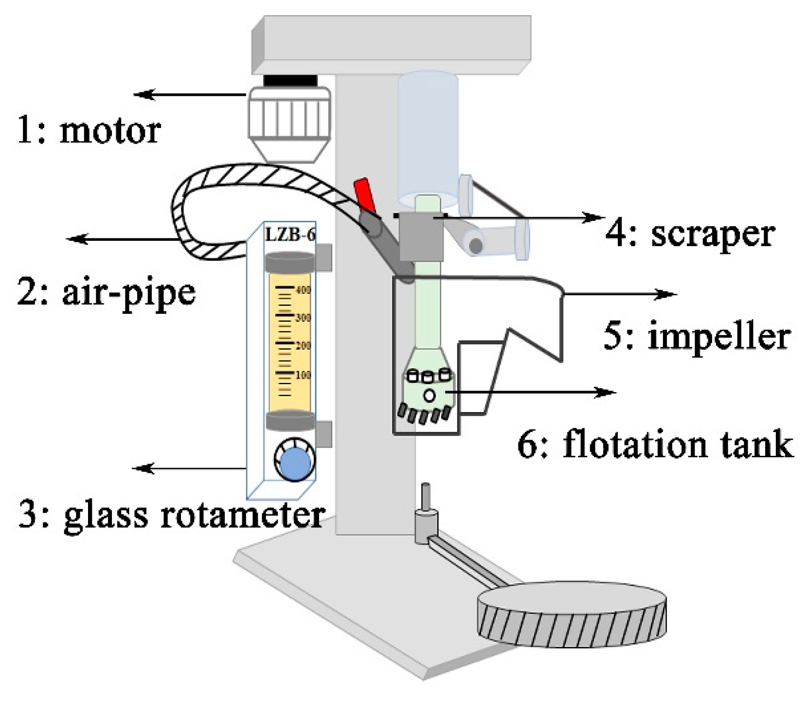
2.2. Experimental Setup and Procedures

2.2.1. Flotation Process

The OSS and OST were treated by a flotation machine (HLXFD-0.5L, Jiangxi Victor International Mining Equipment Co., Ltd., Ganzhou, China), and the schematic diagram of the flotation machine is shown in Figure 1. For each batch experiment, OS and flotation liquid were poured into the tank of the flotation machine to obtain a total volume of 600 mL, and the impeller agitated for 1 min to get well-mixed OS pulp. After the conditioning process, air was introduced into the tank at a flow rate of 60 L/h, and the pulp was floated for fixed flotation time. The upper floating material was collected by the scraper at a rotation speed of 20 r/min, which was named oil phase. The flotation liquid was added to the tank for maintaining a total volume of 600 mL when it was necessary. After flotation, the liquid in the tank was poured off and the residue settling to the tank bottom was collected for further analysis. The flotation liquid was the flotation reagent solution prepared with tap water or only tap water.
The effects of flotation reagent, flotation time, flotation temperature, impeller speed, and the ratio of liquid to OS on OS treatment were evaluated in the batch experiments.
Toluene (AR) and petroleum ether (AR, 60–90 °C) were used to extract oil from OS. Flotation reagents included sodium dodecyl benzene sulfonate (SDBS, CP), polyoxypropylene propylene glycol ether (SP169, CP), and inorganic salts. The inorganic salts of sodium silicate (Na2SiO3, AR), sodium carbonate (Na2CO3, AR), sodium hexametaphosphate ((NaPO3)6, AR), and sodium hydroxide (NaOH, AR) were used in the flotation experiments. The above chemical additives were purchased from Yantai Far East Fine Chemical Co., Ltd., Yantai, China, Guangzhou Detian New Material Co., Ltd., Guangzhou, China, Tianjin Damao Chemical Reagent Factory and Tianjin Zhiyuan Chemical Reagent Co., Ltd., Tianjin, China.

2.2.2. Orthogonal Experimental Design

To explore the key parameters of OS treatment performance, the experiments based on an orthogonal experimental design (OA18 matrix) were conducted, and the following five variables were analyzed: flotation time (parameter Tt), Na2SiO3 concentration (parameter Cc), flotation temperature (parameter Tp), impeller speed (parameter Rs), and the ratio of liquid to OS (parameter L/OS). An OA18 (35) matrix, which is an orthogonal array of five parameters, each with three levels, was employed to assign the considered parameters and levels as shown in Table 3. Eighteen trials were carried out according to the OA18 matrix to complete the exploration process. Each row of orthogonal array represents a run, which is a specific set of parameter levels to be tested. One column can be assigned to a parameter. Data analysis was carried out through the range and correlation analysis to reflect the main influence parameters and their significances. Statistical product and service solutions (24.0) software was used to analyze the correlation between the five parameters and the oil content of residue.
Range analysis has two important parameters: Kji and Rj. Kji is defined as the sum of the oil content of residue of all levels (i, i = 1, 2, 3) in each parameter (j, j = Tt, Cc, Tp, Rs, L/OS) and K ji ¯ is the mean value of Kji. The range value (Rj) indicates the difference between the maximum and minimum value of K ji ¯ . The Rj calculation processes for the OA18 matrix are shown below: for the parameter of Tt in OSS:
K T t 1 = Y 1 + Y 2 + Y 3 + Y 10 + Y 11 + Y 12
K T t 2 = Y 4 + Y 5 + Y 6 + Y 13 + Y 14 + Y 15
K T t 3 = Y 7 + Y 8 + Y 9 + Y 16 + Y 17 + Y 18
K T t 1 ¯ = K T t 1 6 ;   K T t 2 ¯ = K T t 2 6 ;   K T t 3 ¯ = K T t 3 6
R j = max ( K T t i ¯ ) - min ( K T t i ¯ )
where K T t i is defined as the K value of the i level of the parameter of Tt, and Yi is the value of the oil content of residue of the trial No. i for OSS. R values of the OSS or OST parameters can be determined by the same calculation steps.

2.2.3. Analytical Methods

The residue collected from the flotation process was centrifuged in a centrifuge machine (TDZ5-WS, Cence, Changsha, China) at 4000 r/min for 5 min to dehydrate. The oil content of residue was detected by ultraviolet spectrophotometer (UV-5100B, Shanghai Leewen Scientific Instrument Co., Ltd., Shanghai, China) [15].
The surface morphologies of OS and residue were observed by scanning electron microscopy (SEM quanta 250, Fei, Shanghai, China). OS and residue were dried with the air-drying oven (FCD-3000serials, Jiangsu XCH Biomedical Technology Co., Ltd., Taizhou, China) at 105 °C for 4 h, FTIR spectra of OS and residue were obtained on a Nicolet5700 (Thermo Fisher Scientific, Waltham, MA, USA) at a resolution of 0.4 cm−1.

3. Results and Discussion

3.1. Effect of Flotation Parameters on Separation of Oil and Solids in OS

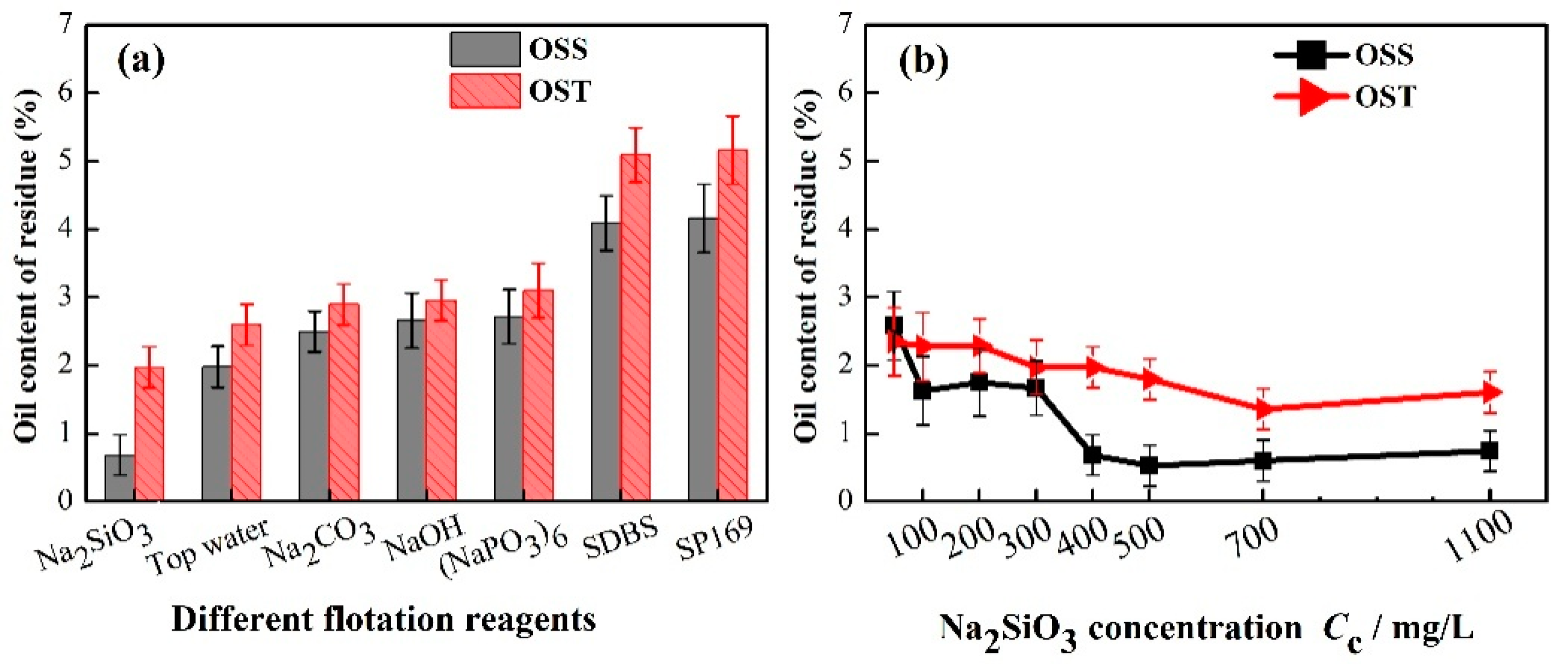
3.1.1. Flotation Reagents Screening

The effect of inorganic salts and surfactants as flotation reagents on the oil content of residue is shown in Figure 2a. The oil content of OSS residue was lower than that of OST residue under the same experimental conditions. Compared with OSS, the H/C atomic ratio was higher, and the O/C atomic ratio was lower for oil in OST, which further proved that the heavy oil component of OST was higher than that of OSS (Table 1). In addition, the solids in OS affect the OS treatment to some degree [29]. The range of size distribution of solids in OSS was wider than that in OST (Table 2), while the particles were concentrated in 10–30 μm of solids of OST, accounting for 79.5%. Gautam et al. found that the collision probability of particles with different diameters was greater than that particles with similar diameters in oil-contaminated soils washing [29].
For the selected flotation reagents, inorganic salts were the better choice than surfactants according to the oil content of residue. The oil contents of OSS and OST residue were both higher using SDBS and SP169 as flotation regents compared with tap water in this study. Bao et al. found the similar trend that the oil content of residue was higher with nonionic surfactant than tap water to treat OS by thermochemical stirring cleaning [3]. Surfactants were selected to increase the solubilization of oil in OS and decrease the oil content of residue, but the OS treatment using flotation did not get the expected results. It is speculated the solubilization of surfactants resulted in many smaller oil droplets in flotation liquid, and it was difficult for bubbles entraining smaller oil droplets to float up; meanwhile, the oil, surfactant solution and solids of pulp tended to return to emulsion state at high-speed shearing condition [3]. However, Ramaswamy et al. discovered the oil recovery increased with the increasing of SDBS dose when the froth flotation was applied to treat artificial OS with Mobil oil contaminating pulverized soil [25]. There was difference between artificial and industrial OS. For industrial OS, the compositions of the oil and solid in OS are more complex, and the network structure is more stable. Thus, it was more difficult to sperate oil from the solid surface in aged OS collected from oilfield, and the solubilization effect of surfactant was limited and might promote further emulsion of oil at high-speed shearing. Hence, surfactants were not the ideal reagents for OS samples treatment with flotation in this study.
Na2SiO3 was chosen acted as a dispersant during the flotation treatment for the next experiments [23,34]. When the Na2SiO3 concentration increased from 50 to 400 mg/L, the oil content of OSS residue decreased from 2.6% to 0.7%, and the downward trend slowed down after 400 mg/L (Figure 2b). The oil content of OST residue changing with the Na2SiO3 concentration were similar to that of OSS residue. The lipophilicity of solids in OS hindered the desorption of oil adhering on the solid surface [6]. The Na2SiO3 added as flotation reagent absorbed on the oil droplets and enhanced the hydrophilicity of oil droplets, which induced the affinity between oil droplets and solids to decrease. The result was that it is easier for the separation of oil from the solid surface. At the same time, the addition of Na2SiO3 could prevent bubbles from coalescing to improve bubble stability and increase their residence time in the pulp [20]. The bubbles diameter decreased, and the number of bubbles increased with the increasing of Na2SiO3 concentration, and the floating speed of bubbles decreased [35]. This increased the collision probability between bubbles and oil droplets and reduced the detachment probability of oil droplets [35,36,37], hereby reducing the oil contents of OSS and OST residue. The Na2SiO3 concentration of 400 mg/L was chosen for the subsequent experiments, considering the efficiency and cost of treating OS.

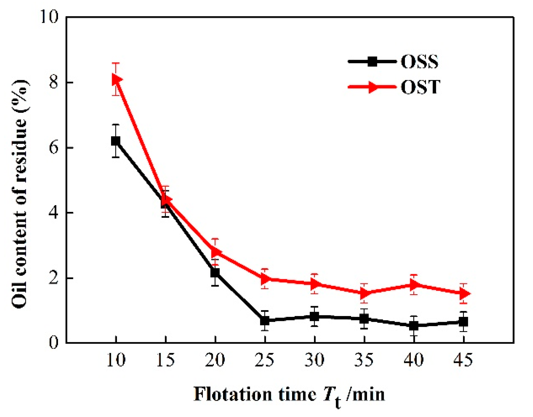
3.1.2. Flotation Time

Data from the flotation time experiments are illustrated graphically in Figure 3. The collected oil phase was increasing with the increasing of flotation time, and the oil content of residue would decrease. As the flotation time was further extended, the shear effect of the impeller became more significant [20], which facilitated the separation of oil from solid surface and decreased the oil content of residue. When the flotation time was 25 min, the oil contents of OSS and OST residue reached 0.7% and 1.9%, respectively. After that, the oil contents of OSS and OST residue reduced to a small extent with flotation time. The easily separable oil had essentially been removed in 25 min. Less residual oil on solids could be separated from solid surface increasing flotation time, while the energy consumption increased. Therefore, flotation time of 25 min was found to be optimal.

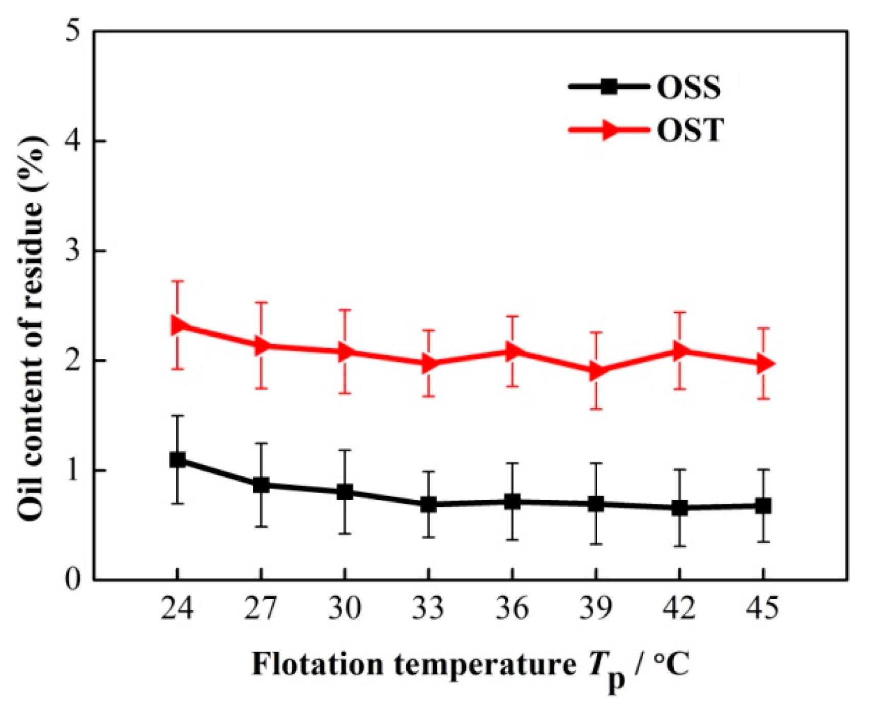
3.1.3. Flotation Temperature

As shown in Figure 4, the oil content of residue changed mildly with flotation temperature. It can be seen that the oil contents of OSS and OST residue decreased slightly at first with the flotation temperature below 33 °C and then remained at around 0.7% and 1.9% over 33 °C, respectively. Increasing the temperature of OS pulp could reduce the viscosity of OS, and it was easier to separate oil from the solid surface [38]. Flotation temperature had no significant effect on OS treatment in this study, and which was consistent with the experimental results of treating Jordanian tar sands with flotation [24,27]. Awni et al. found that the bitumen recovery of Jordanian tar sands reached 78.0% at 25 °C, and it only increased by 8.0% at 80 °C [24]. High-speed shearing of flotation machine could also reduce the viscosity of pulp [18], and the effect of increasing flotation temperature to reduce pulp viscosity was less by comparison. Moreover, solution temperature of more than 77 °C caused evaporation of water and organic substances, such as olefins and aromatics [39]. Hence, OS treatment using flotation not only reduced the oil content of residue to less than 2% at temperature of 24–45 °C, but also reduced the volatilization of hydrocarbons.

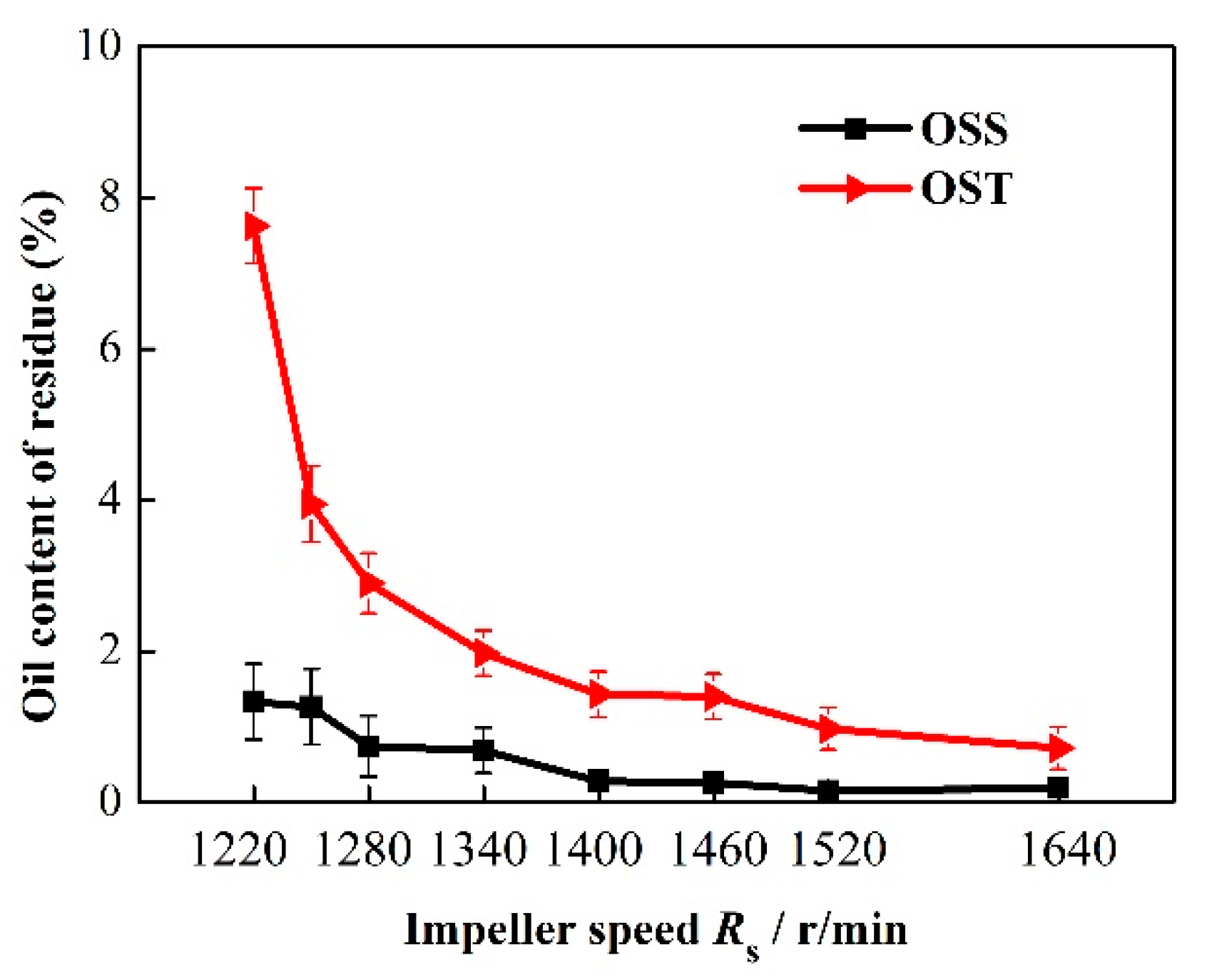
3.1.4. Impeller Speed

Data from the impeller speed experiment are illustrated graphically in Figure 5. The oil contents of OSS and OST residue were high when the impeller speed was low. When the impeller speed increased from 1220 to 1640 r/min, the oil contents of OSS and OST residue decreased from 1.3% to 0.2%, and from 7.6% to 0.7%, respectively. The unique turbulent flow field could be formed, all solid particles in OS pulp were dispersed, and the oil was separated from the surface of solid particles by high shear force generated at high impeller speed. In addition, the high impeller speed generated a vacuum region, which sucked in air to form air flotation [37]. Meanwhile, the bubble size decreased with the increasing of impeller speed and tended to be stable [40]. Due to air flotation, the oil droplets separated from the solid surface were carried by the bubbles to the upper surface in time to prevent the oil droplets from being reabsorbed by the solids. The dispersion of oil on the bubble surface reduced the density of oil droplets and increased the aggregates diameter, which expanded the density difference between oil aggregates and water. The final result was that the rising rate of oil aggregates was increased. However, high impeller speed exceeding a critical value might induce the increasing of bubble size and then the flotation recovery decreased [41]. In addition, higher impeller speed disturbed the upper liquid level of the flotation tank, which was the adverse factor to the formation of a stable foam layer. The shorter the contact time between the oil droplets and bubbles, the more the oil content of residue increased. Therefore, there was a critical value of the impeller speed for OS treatment using flotation.

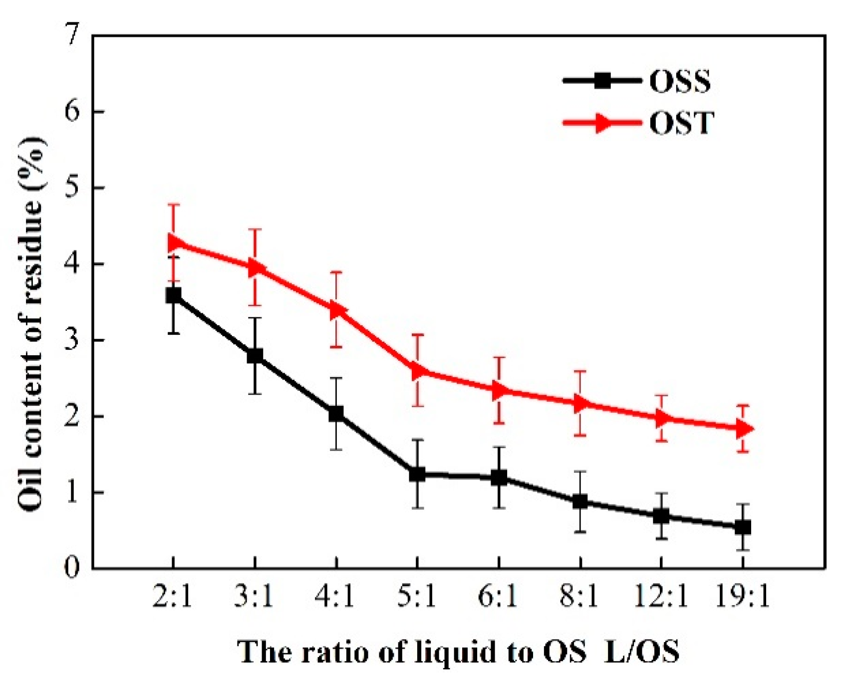
3.1.5. The Ratio of Liquid to OS

The plots of the oil content of residue against the ratio of liquid to OS decreased initially but remained almost constant at higher ratio of liquid to OS, as shown in Figure 6. When the ratio of liquid to OS increased from 12:1 to 19:1, the oil content of OSS residue decreased from 0.7% to 0.5%, and the reduction for OST residue was only 0.1%. For a constant total volume of flotation tank, the viscosity of pulp increased with the decreasing of the ratio of liquid to OS, which prevented the bubbles from rising. The higher proportion of liquid in the flotation tank not only contributed to shear the OS completely, but also facilitated the formation of air bubbles. The result was the increase of the effective contact area between bubbles and OS promoted the further separation of oil phase from solid surface. Hence, the ratio of liquid to OS had effect on OS treatment using flotation.

3.2. Analysis of Orthogonal Experimental Results

Based on the single factor experiments, the orthogonal experiment was used to further explore the main parameters of OS flotation performance. According to the OA18 matrix, eighteen experiments were carried out and the results of the oil content of residue are presented in Table 4. It can be seen from Table 4 that the range of the oil content of OSS residue varied from 0.6% to 7.7%, and that of OST residue varied from 1.2% and 17.5%, which were the original data and used in the range and correlation analysis. The mean values of K ( K ji ¯ ) for different parameters at different levels in the range analysis are shown in Table 5. The range value (Rj) indicated the significance of the parameter’s effect and a larger Rj meant the parameter had a bigger impact on the maximum biodiesel production yield [42]. Therefore, compared with the range values of different parameters (Rj), the parameters’ levels of significance for OSS were as follows: impeller speed > the ratio of liquid to OS > flotation temperature > Na2SiO3 concentration > flotation time; for OST: impeller speed > the ratio of liquid to OS > flotation time > flotation temperature > Na2SiO3 concentration. The influencing parameters of OSS and OST had slightly different orders, which could be due to the difference in physicochemical properties of OSS and OST. The range value of impeller speed (RRs) for OSS and OST was the largest, which indicated that impeller speed was the main parameter affecting OSS and OST flotation. The range values of the Na2SiO3 concentration (RCc) and flotation temperature (RTp) were small, and both factors had little effect on the oil contents of OSS and OST residue as shown in Figure 2 and Figure 4. The results of correlation analysis in Table 6 also showed that the correlation between impeller speed and the oil contents of OSS and OST residue was very significant, while the other parameters were insignificant. This demonstrated that a small change of impeller speed had a significant influence on the OS flotation treatment.

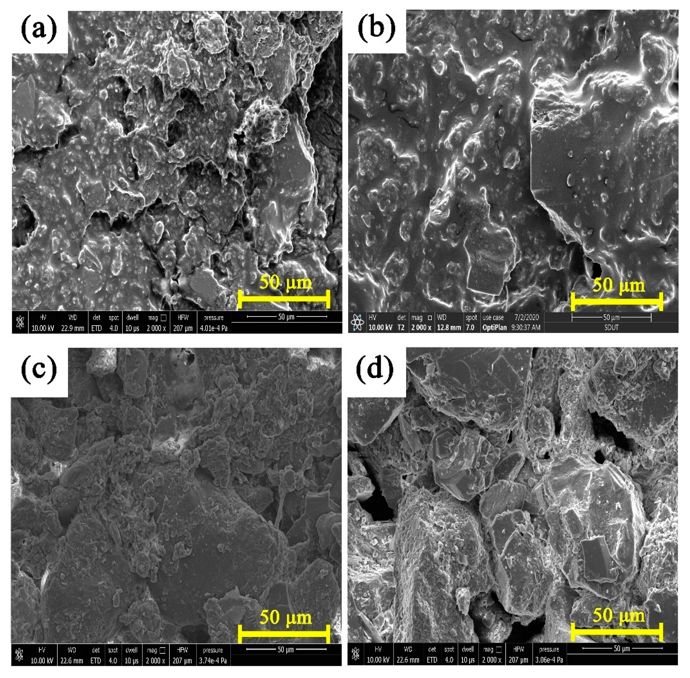
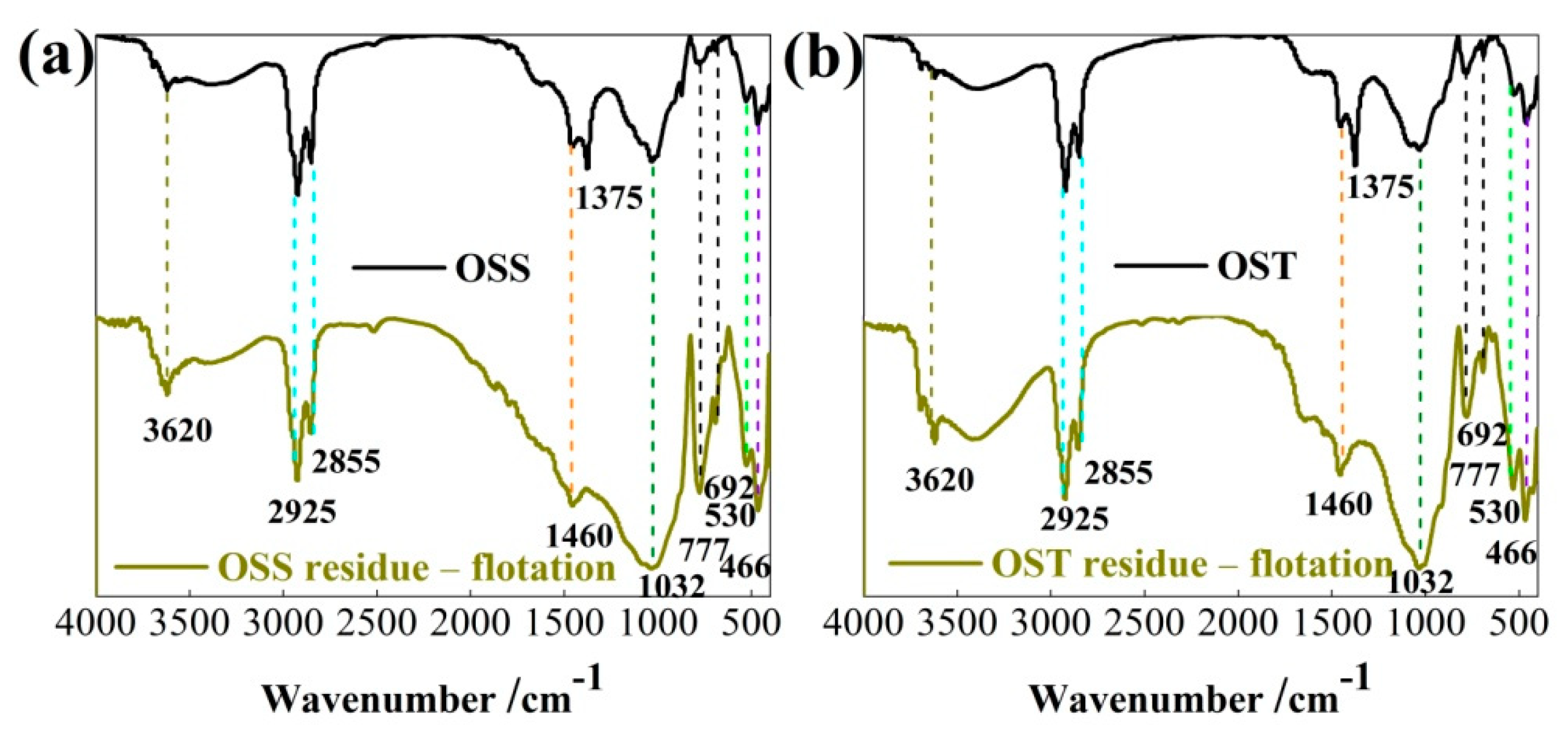
3.3. SEM Image and FTIR Analysis of OS and Residue

SEM image (Figure 7) shows that OS samples were water-in-oil (W/O) type emulsion, and the solid particles dispersed in the oil, or absorbed on the W/O interface, forming a dense network structure. Stony granular materials can be seen on the solid surface of OSS and OST after flotation. The surface of residue has loose open space structures, rich porous structure, and clear voids. This illustrates that the black viscous oil adhering on the solid surface disappeared after flotation. The similar surface phenomena of OS and residue were found in OS treatment by pyrolysis [15] or water-enhanced CO2 extraction [43].
To further explore the chemical properties effect of flotation on the OS, the chemical bonds of OS and residue are analyzed by FTIR spectra, as shown in Figure 8. Compared with OSS and OST, OSS and OST residue did not form new bonds after flotation treatment. The absorption peaks of FTIR spectra in the range from 466 to 777 cm−1 could be attributed to the asymmetric bending vibrations of Si-O-Si, the stretching vibrations of Si-O-Al in hematite, and the symmetric bending and stretching vibrations of Si-O in quartz. The broad absorption peak at 1032 cm−1 corresponds to the stretching vibrations of Si-O in kaolinite, while the intensity of 1032 cm−1 in the residue increased after flotation, which indicated that the oil was removed. The 1375 cm−1 peak ascribing to symmetrical bending vibration of C-H in methyl disappeared in residue, which was attributed to the removal of alkanes by flotation. The asymmetric bending vibrations, symmetric and asymmetric stretching vibrations of C-H in aliphatic groups methyl and methylene of asphaltene appear at 1460, 2855, and 2925 cm1, respectively. Compared with the FTIR spectra of OS and residue, the peaks at 1460, 2855 and 2925 cm−1 in the residue were weakened, but the strength still existed, which indicates that there were still some asphaltene aliphatic groups in the residue. This illustrated that it was difficult to crack the branched or side chains of asphaltene aliphatic group by flotation. The peak at 3620 cm−1 corresponds to the stretching vibrations of O-H in kaolinite.

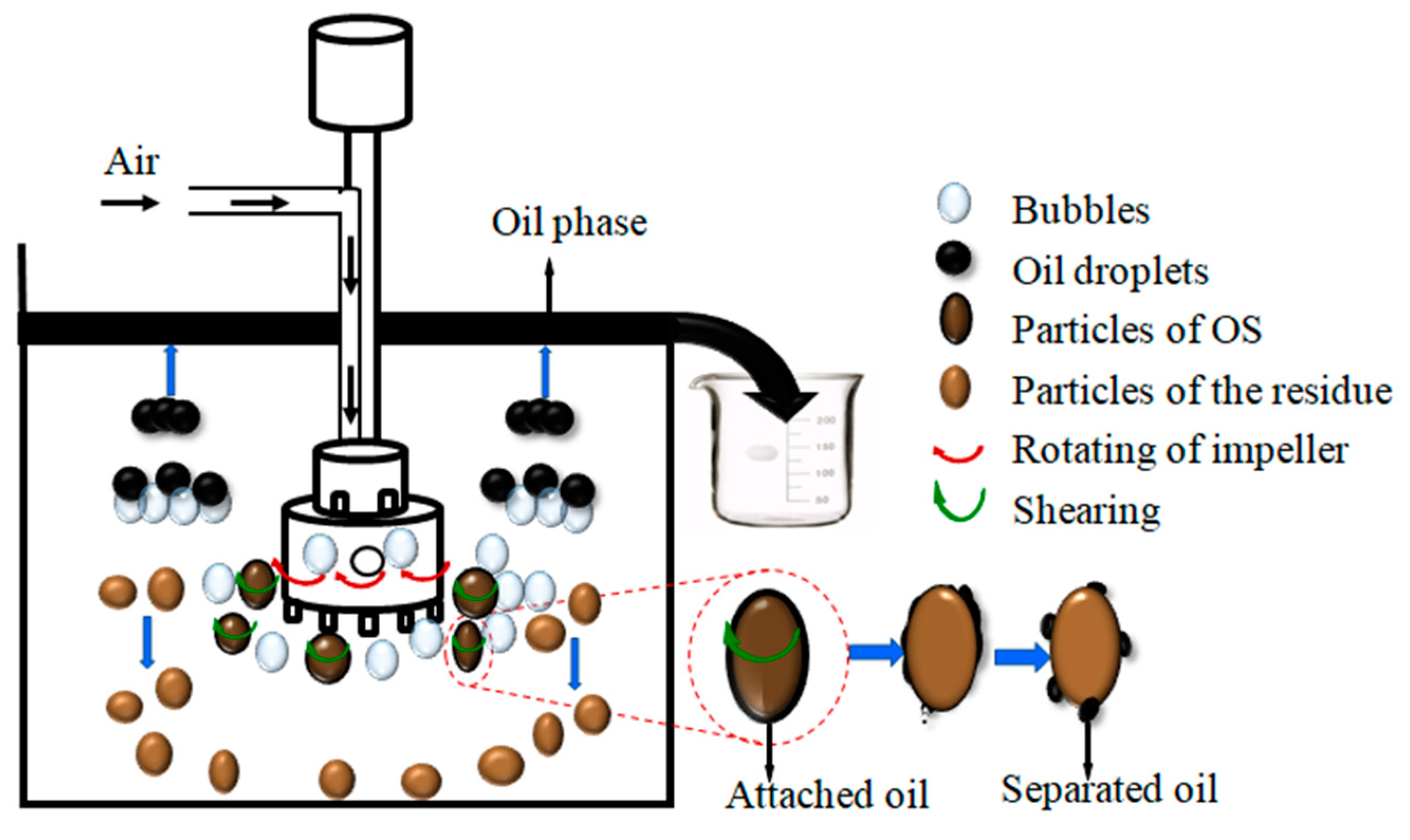
3.4. Mechanism of Froth Flotation Treating OS

The mechanism of froth flotation treating OS was showed in Figure 9. The impeller could stir the mixture of OS and flotation liquid evenly at high speed, and generated shear force to separate the oil from the surface of solid particles. In addition, the impeller rotating at a high-speed generated a vacuum region and sucked the air to create bubbles. The bubbles carried the oil droplets liberated from solid particles to upper surface in time preventing the oil droplets from attaching to the solid particles again. Oil droplets carried by bubbles mainly included the following processes [19,20,25]. Firstly, a film was formed on the surfaces of the droplets and bubbles when the oil droplets and bubbles approached under hydrodynamic action. Secondly, the film drained away, and dimples appeared on the surfaces of oil droplets and bubbles. Thirdly, molecular forces further broke the film, and the oil diffused to the surface of bubbles to form oil aggregates. Finally, the oil aggregates rose to the surface.

4. Conclusions

The treatment efficiency of OS was related to heavy components of oil and particle size distribution of solids in OS. The oil content of OSS residue was lower than that of OST under the same flotation conditions. The suitable flotation reagent Na2SiO3 was found from the selected inorganic salts and surfactants for treating OS. The shear effect increased with increasing flotation time, which facilitated oil-solid separation. Increasing impeller speed can produce stronger shear strength and air flotation that results in improved oil separation from a solid surface. However, excessive impeller speed hindered the formation of stable foam layer and further shortened the contact time between the oil droplets and bubbles. Increasing the ratio of liquid to OS promoted the formation of bubbles and increased the effective area between the bubble and the OS, which facilitated the oil separation from solid surface. In addition, Na2SiO3 concentration and flotation temperature had limited effect on the oil content of residue under the condition of high impeller speed.
Based on orthogonal experimental results and ranges analysis, the final ranking of the significance of parameters in the oil content of OSS residue was determined to be as follows: impeller speed > the ratio of liquid to OS > flotation temperature > Na2SiO3 concentration > flotation time. As for OST treatment by flotation, the order of the significance of parameters was the same, except that the flotation time was ahead of the Na2SiO3 concentration. Based on the SEM image of OS and residue, the structure of residue was loose, and rocks can be seen clearly after flotation. For the residue, it was found the intensity of the C-H bonds decreased and the Si-O bonds increased through FTIR analysis, most of the oil phase was separated from solid surface. Residue contained oil under the optimized flotation parameters, which attributed to cracking the branched or side chains of asphaltene aliphatic group was difficult by flotation.
These results indicated that the separation of oil from solids can be achieved under high shear force with conventional technology of froth flotation, provided suitable optimization and an inorganic salt were used. The oil content of OST and OSS residue could be reduced to 1.2% and 0.6%, which indicated froth flotation was the future potential technology in low-cost, largescale treatment of OS.

Author Contributions

Conceptualization, W.L. and Y.M.; methodology, Q.L.; software, W.L.; validation, H.L.; formal analysis, W.L.; investigation, Y.Y.; resources, Y.M.; data curation, A.L.; writing—original draft preparation, A.L.; writing—review and editing, Z.S.; visualization, Z.S.; supervision, W.L.; project administration, M.J. and Y.M.; funding acquisition, M.J. and Y.M. All authors have read and agreed to the published version of the manuscript.

Funding

This research was funded by the Shandong Provincial Natural Science Foundation (ZR2020MD108, ZR2020ZD19), the Yellow River Delta Research Institute Innovation Research Foundation Program (118171), the National Natural Science Foundation of China (51804188), and Ph.D. Program of Shandong Provincial Natural Science Foundation (ZR2018BEE015).

Institutional Review Board Statement

Not applicable.

Informed Consent Statement

Not applicable.

Data Availability Statement

All data are available and can be shared upon request.

Conflicts of Interest

The authors declare no conflict of interest.

References

  1. Li, J.; Lin, F.; Li, K.; Zheng, F.; Yan, B.; Che, L.; Tian, W.; Chen, G.; Yoshikawa, K. A critical review on energy recovery and non-hazardous disposal of oily sludge from petroleum industry by pyrolysis. J. Hazard. Mater. 2021, 406, 124706. [Google Scholar] [CrossRef] [PubMed]
  2. Gao, N.; Duan, Y.; Li, Z.; Quan, C.; Yoshikawa, K. Hydrothermal treatment combined with in-situ mechanical compression for floated oily sludge dewatering. J. Hazard. Mater. 2021, 402, 124173. [Google Scholar] [CrossRef] [PubMed]
  3. Bao, Q.; Huang, L.; Xiu, J.; Yi, L.; Ma, Y. Study on the treatment of oily sludge in oil fields with lipopeptide/sophorolipid complex bio-surfactant. Ecotoxicol. Environ. Saf. 2021, 212, 111964. [Google Scholar] [CrossRef]
  4. Hui, K.; Tang, J.; Lu, H.; Xi, B.; Qu, C.; Li, J. Status and prospect of oil recovery from oily sludge: A review. Arab. J. Chem. 2020, 13, 6523–6543. [Google Scholar] [CrossRef]
  5. Hu, G.; Li, J.; Zeng, G. Recent development in the treatment of oily sludge from petroleum industry: A review. J. Hazard. Mater. 2013, 261, 470–490. [Google Scholar] [CrossRef]
  6. Zhao, M.; Wang, X.; Liu, D.; Li, Z.; Guo, S.; Zhu, W.; Shi, N.; Wen, F.; Dong, J. Insight into essential channel effect of pore structures and hydrogen bonds on the solvent extraction of oily sludge. J. Hazard. Mater. 2020, 389, 121826. [Google Scholar] [CrossRef]
  7. Hamidi, Y.; Ataei, S.A.; Sarrafi, A. A simple, fast and low-cost method for the efficient separation of hydrocarbons from oily sludge. J. Hazard. Mater. 2021, 413, 125328. [Google Scholar] [CrossRef] [PubMed]
  8. Luo, X.; Gong, H.; He, Z.; Zhang, P.; He, L. Research on mechanism and characteristics of oil recovery from oily sludge in ultrasonic fields. J. Hazard. Mater. 2020, 399, 123137. [Google Scholar] [CrossRef]
  9. Gao, Y.-X.; Ding, R.; Chen, X.; Gong, Z.-B.; Zhang, Y.; Yang, M. Ultrasonic washing for oily sludge treatment in pilot scale. Ultrasonics 2018, 90, 1–4. [Google Scholar] [CrossRef] [PubMed]
  10. Li, J.; Lin, F.; Xiang, L.; Zheng, F.; Che, L.; Tian, W.; Guo, X.; Yan, B.; Song, Y.; Chen, G. Hazardous elements flow during pyrolysis of oily sludge. J. Hazard. Mater. 2021, 409, 124986. [Google Scholar] [CrossRef]
  11. Hu, G.; Li, J.; Hou, H. A combination of solvent extraction and freeze thaw for oil recovery from petroleum refinery wastewater treatment pond sludge. J. Hazard. Mater. 2015, 283, 832–840. [Google Scholar] [CrossRef]
  12. Duan, M.; Wang, X.; Fang, S.; Zhao, B.; Li, C.; Xiong, Y. Treatment of Daqing oily sludge by thermochemical cleaning method. Colloids Surf. A Physicochem. Eng. Asp. 2018, 554, 272–278. [Google Scholar] [CrossRef]
  13. Zhang, J.; Li, J.; Thring, R.W.; Hu, X.; Song, X. Oil recovery from refinery oily sludge via ultrasound and freeze/thaw. J. Hazard. Mater. 2012, 203–204, 195–203. [Google Scholar] [CrossRef] [PubMed]
  14. Jean, D.; Lee, D.; Wu, J.C.S. Separation of oil from oily sludge by freezing and thawing. Water Res. 1999, 33, 1756–1759. [Google Scholar] [CrossRef]
  15. Liu, Y.; Zhang, Q.; Wu, B.; Li, X.; Ma, F.; Li, F.; Gu, Q. Hematite-facilitated pyrolysis: An innovative method for remediating soils contaminated with heavy hydrocarbons. J. Hazard. Mater. 2020, 383, 121165. [Google Scholar] [CrossRef]
  16. Lin, B.; Huang, Q.; Chi, Y. Co-pyrolysis of oily sludge and rice husk for improving pyrolysis oil quality. Fuel Process. Technol. 2018, 177, 275–282. [Google Scholar] [CrossRef]
  17. Lee, T.; Nam, I.-H.; Kim, J.-H.; Zhang, M.; Jeong, T.Y.; Baek, K.; Kwon, E.E. The enhanced thermolysis of heavy oil contaminated soil using CO2 for soil remediation and energy recovery. J. CO2 Util. 2018, 28, 367–373. [Google Scholar] [CrossRef]
  18. Forbes, E. Shear, selective and temperature responsive flocculation: A comparison of fine particle flotation techniques. Int. J. Miner. Process. 2011, 99, 1–10. [Google Scholar] [CrossRef]
  19. Saththasivam, J.; Loganathan, K.; Sarp, S. An overview of oil–water separation using gas flotation systems. Chemosphere 2016, 144, 671–680. [Google Scholar] [CrossRef]
  20. Moosai, R.; Dawe, R.A. Gas attachment of oil droplets for gas flotation for oily wastewater cleanup. Sep. Purif. Technol. 2003, 33, 303–314. [Google Scholar] [CrossRef]
  21. Etchepare, R.; Oliveira, H.; Azevedo, A.; Rubio, J. Separation of emulsified crude oil in saline water by dissolved air flotation with micro and nanobubbles. Sep. Purif. Technol. 2017, 186, 326–332. [Google Scholar] [CrossRef]
  22. Yu, L.; Han, M.; He, F. A review of treating oily wastewater. Arab. J. Chem. 2017, 10, S1913–S1922. [Google Scholar] [CrossRef] [Green Version]
  23. Stasiuk, E.N.; Schramm, L.L. The influence of solvent and demulsifier additions on nascent froth formation during flotation recovery of Bitumen from Athabasca oil sands. Fuel Process. Technol. 2001, 73, 95–110. [Google Scholar] [CrossRef]
  24. Al-Otoom, A.; Allawzi, M.; Al-Omari, N.; Al-Hsienat, E. Bitumen recovery from Jordanian oil sand by froth flotation using petroleum cycles oil cuts. Energy 2010, 35, 4217–4225. [Google Scholar] [CrossRef]
  25. Ramaswamy, B.; Kar, D.D.; De, S. A study on recovery of oil from sludge containing oil using froth flotation. J. Environ. Manag. 2007, 85, 150–154. [Google Scholar] [CrossRef]
  26. Guo, S.; Li, G.; Qu, J.; Liu, X. Improvement of acidification on dewaterability of oily sludge from flotation. Chem. Eng. J. 2011, 168, 746–751. [Google Scholar] [CrossRef]
  27. Li, H.; Zhou, Z.A.; Xu, Z.; Masliyah, J.H. Role of Acidified Sodium Silicate in Low Temperature Bitumen Extraction from Poor-Processing Oil Sand Ores. Ind. Eng. Chem. Res. 2005, 44, 4753–4761. [Google Scholar] [CrossRef]
  28. Zhang, H.; Liu, J.; Cao, Y.; Wang, Y. Effects of particle size on lignite reverse flotation kinetics in the presence of sodium chloride. Powder Technol. 2013, 246, 658–663. [Google Scholar] [CrossRef]
  29. Gautam, P.; Bajagain, R.; Jeong, S.-W. Combined effects of soil particle size with washing time and soil-to-water ratio on removal of total petroleum hydrocarbon from fuel contaminated soil. Chemosphere 2020, 250, 126206. [Google Scholar] [CrossRef] [PubMed]
  30. Mousset, E.; Oturan, M.A.; van Hullebusch, E.D.; Guibaud, G.; Esposito, G. Soil Washing/Flushing Treatments of Organic Pollutants Enhanced by Cyclodextrins and Integrated Treatments: State of the Art. Crit. Rev. Environ. Sci. Technol. 2014, 44, 705–795. [Google Scholar] [CrossRef]
  31. Ni, C.; Xie, G.; Jin, M.; Peng, Y.; Xia, W. The difference in flotation kinetics of various size fractions of bituminous coal between rougher and cleaner flotation processes. Powder Technol. 2016, 292, 210–216. [Google Scholar] [CrossRef]
  32. Anzoom, S.J.; Tripathy, S.K.; Sahu, L.; Bhattacharya, S.; Mukherjee, A. Influence of impeller speed and cell volume on coal flotation performance in a self-aerating flotation machine. Adv. Powder Technol. 2020, 31, 4053–4063. [Google Scholar] [CrossRef]
  33. Mu, B.; Zhu, W.; Zhong, J.; Chen, L.; Lin, N.; Wang, C.; Chen, S.; Li, Z. Mechanism of separation and removal of water from oily sludge using liquid dimethyl ether to dissolve hydrocarbons. Chemosphere 2021, 279, 130452. [Google Scholar] [CrossRef] [PubMed]
  34. Tao, X.; Liu, Y.; Jiang, H.; Chen, R. Microbubble generation with shear flow on large-area membrane for fine particle flotation. Chem. Eng. Process.-Process Intensif. 2019, 145, 107671. [Google Scholar] [CrossRef]
  35. Fan, M.; Tao, D.; Honaker, R.; Luo, Z. Nanobubble generation and its application in froth flotation (part I): Nanobubble generation and its effects on properties of microbubble and millimeter scale bubble solutions. Min. Sci. Technol. 2010, 20, 1–19. [Google Scholar] [CrossRef]
  36. Girgin, E.; Do, S.; Gomez, C.O.; Finch, J. Bubble size as a function of impeller speed in a self-aeration laboratory flotation cell. Miner. Eng. 2006, 19, 201–203. [Google Scholar] [CrossRef]
  37. Koh, P.T.L.; Schwarz, M.P. CFD model of a self-aerating flotation cell. Int. J. Miner. Process. 2007, 85, 16–24. [Google Scholar] [CrossRef] [Green Version]
  38. Lu, Z.; Liu, W.; Bao, M.; Zhao, L.; Sun, X.; Lu, J.; Li, Y. Oil recovery from polymer-containing oil sludge in oilfield by thermochemical cleaning treatment. Colloids Surf. A Physicochem. Eng. Asp. 2021, 611, 125887. [Google Scholar] [CrossRef]
  39. Lv, X.; Song, Z.; Yu, J.; Su, Y.; Zhao, X.; Sun, J.; Mao, Y.; Wang, W. Study on the demulsification of refinery oily sludge enhanced by microwave irradiation. Fuel 2020, 279, 118417. [Google Scholar] [CrossRef]
  40. Amini, E.; Bradshaw, D.J.; Finch, J.; Brennan, M. Influence of turbulence kinetic energy on bubble size in different scale flotation cells. Miner. Eng. 2013, 45, 146–150. [Google Scholar] [CrossRef]
  41. Shahbazi, B.; Rezai, B.; Javad Koleini, S.M. The effect of hydrodynamic parameters on probability of bubble–particle collision and attachment. Miner. Eng. 2009, 22, 57–63. [Google Scholar] [CrossRef]
  42. Wu, X.; Leung, D.Y.C. Optimization of biodiesel production from camelina oil using orthogonal experiment. Appl. Energy 2011, 88, 3615–3624. [Google Scholar] [CrossRef]
  43. Wu, X.-F.; Qin, H.-B.; Zheng, Y.-X.; Zhang, Y.; Chen, W.; Zuo, J.Y.; Sun, C.-Y.; Chen, G.-J. A novel method for recovering oil from oily sludge via water-enhanced CO2 extraction. J. CO2 Util. 2019, 33, 513–520. [Google Scholar] [CrossRef]
Figure 1. Schematic diagram of the flotation machine.
Processes 09 02163 g001
Figure 2. The oil content of residue changing with (a) flotation reagents and (b) Na2SiO3 concentrations. Data plotted as mean of duplicates and the error bars indicate data reproducibility. Flotation conditions: Cc = 400 mg/L, Tt = 25 min, Tp = 33 °C, Rs = 1340 r/min, L/OS = 12:1.
Processes 09 02163 g002
Figure 3. The oil content of residue changing with flotation time. Flotation conditions: Cc = 400 mg/L, Tp = 33 °C, Rs = 1340 r/min, L/OS = 12:1.
Processes 09 02163 g003
Figure 4. Influence of flotation temperature on the oil content of residue. Flotation conditions: Cc = 400 mg/L, Tt = 25 min, Rs = 1340 r/min, L/OS = 12:1.
Processes 09 02163 g004
Figure 5. Influence of impeller speed on the oil content of residue. Flotation conditions: Cc = 400 mg/L, Tt = 25 min, Tp = 33 °C, L/OS = 12:1.
Processes 09 02163 g005
Figure 6. Influence of the ratio of liquid to OS on the oil content of residue. Flotation conditions: Cc = 400 mg/L, Tt = 25 min, Tp = 33 °C, Rs = 1340 r/min.
Processes 09 02163 g006
Figure 7. SEM images of (a) OSS, (b) OST, (c) OSS residue, and (d) OST residue. Flotation conditions: Tt = 25 min, Cc = 400 mg/L, Tp = 33 °C, Rs = 1340 r/min, L/OS = 12:1.
Processes 09 02163 g007
Figure 8. (a) FTIR spectra of the OSS and OSS residue from flotation treatment; (b) FTIR spectra of the OST and OST residue from flotation treatment; Flotation conditions: Tt = 25 min, without chemical additive, Tp = room temperature (24 °C), Rs = 1340 r/min, L/OS = 12:1.
Processes 09 02163 g008
Figure 9. Mechanism of oil separation from solid particles by froth flotation.
Processes 09 02163 g009
Table 1. Elemental composition and four components of oil in OS.
OS SampleElemental Composition (wt%)Four Components (wt%)
CHSNOSaturatesAromaticsResinsAsphaltenes
OSS74.59.62.60.512.857.530.56.85.2
OST81.610.62.40.45.055.328.89.36.6
Table 2. Composition and particle size distribution of the solids in OS.
OS SampleMineral Composition (%)Particle Size Distribution (%)
SiO2Al2O3CaOFe2O3SO3K2OMgOOthers a0–10 μm10–30 μm30–100 μm
OSS49.014.011.67.77.32.72.45.362.424.513.1
OST55.415.06.16.95.32.92.55.93.079.517.5
a Others refer to the other minerals not mentioned in the table.
Table 3. Levels and parameters affecting the oil content of residue.
LevelParameters
Flotation Time (min)Concentration (mg/L)Temperature (°C)Impeller Speed (r/min)The Ratio of Liquid to OS
TtCcTpRsL/OS
11010024122019:1
22540033134012:1
3407004214605:1
Table 4. Oil content of residue in OA18 matrix.
Trial No.ParametersOil Content of
OSS ResidueOST Residue
TtCcTpRsL/OSYiGi
11010024122019:11.815.7
21040033134012:11.47.7
3107004214605:11.42.2
42510024134012:11.12.4
52540033146019:10.61.2
6257004212205:14.810.0
7401003312205:15.715.1
84040042134019:11.01.8
94070024146012:10.71.3
101010042146012:11.22.7
11104002412205:14.017.5
121070042134019:11.83.4
132510033146019:11.11.2
142540042122012:13.910.4
15257002413405:10.73.0
16401004213405:10.72.3
174040024146019:10.81.4
184070033122012:17.713.5
Table 5. Range analysis data of the oil content of residue.
Value NameOil Content of OSS ResidueOil Content of OST Residue
TtCcTpRsL/OSTtCcTpRsL/OS
K 1 ¯ 1.91.91.54.71.28.26.66.913.74.1
K 2 ¯ 2.01.83.01.12.74.76.67.03.46.3
K 3 ¯ 2.82.92.21.02.95.95.64.91.78.3
Rj0.81.01.53.71.73.51.12.112.04.2
Ranking of influencing parametersRs > L/OS > Tp > Cc > TtRs > L/OS > Tt > Tp > Cc
Table 6. Results of statistical product and service solutions correlation analysis.
Correlation
TtCcTpRsL/OSOil Content of OSS ResidueOil Content of OST Residue
TtPearson Correlation10.0000.0000.0000.0000.169−0.166
Sig. (2-tailed) 1.0001.0001.0001.0000.5030.511
N18181818181818
CcPearson Correlation0.00010.0000.000−0.1670.186−0.072
Sig. (2-tailed)1.000 1.0001.0000.5090.4610.776
N18181818181818
TpPearson Correlation0.0000.00010.000−0.1670.132−0.143
Sig. (2-tailed)1.0001.000 1.0000.5090.6020.571
N18181818181818
RsPearson Correlation0.0000.0000.00010.333−0.746 **−0.868 **
Sig. (2-tailed)1.0001.0001.000 0.1770.0000.000
N18181818181818
L/OSPearson Correlation0.000−0.167−0.1670.3331−0.350−0.305
Sig. (2-tailed)1.0000.5090.5090.177 0.1550.218
N18181818181818
Oil content of OSS residuePearson Correlation0.1690.1860.132−0.746 **−0.35010.775 **
Sig. (2-tailed)0.5030.4610.6020.0000.155 0.000
N18181818181818
Oil content of OST residuePearson Correlation−0.166−0.072−0.143−0.868 **−0.3050.775 **1
Sig. (2-tailed)0.5110.7760.5710.0000.2180.000
N18181818181818
**. Correlation is significant at the 0.01 level (2-tailed).
Publisher’s Note: MDPI stays neutral with regard to jurisdictional claims in published maps and institutional affiliations.

