1. Introduction
Contemporary dentistry requires extensive engineering support consisting of the synergistic use of extensive knowledge in the field of material engineering, manufacturing engineering, and tissue engineering covered by the current stage of Industry 4.0 of the industrial revolution [
1,
2,
3,
4,
5,
6,
7]. Stadium Industry 4.0 is associated with systematically implemented cyber-physical systems. An essential element of those activities is to achieve the Materials 4.0 stage of material design [
1,
8,
9] as part of a complex engineering design process also involving structural and technological design. The Industry 4.0 model, resulting directly from the original reports introducing this approach [
2,
3,
4,
5], however, proved to be incomplete. Criticism of this model led to the development of the authors’ extended holistic model Industry 4.0 [
1,
6,
7,
10]. This model is located in the current one appropriately extended as one of the four components of the technological plane. This technological plane also contains materials, technological machines and devices, as well as technological processes together with additive methods that cannot be considered as the only ones needed in modern industry. As part of this approach, digitisation and computerisation in dentistry are described as Dentistry 4.0 [
1,
10,
11,
12,
13].
Figure 1 is a schematic diagram illustrating the synergistic interaction of the three pillars of the Dentistry 4.0 model, including dentistry, dental engineering and material engineering.
In modern dentistry, as well as in medicine in general, various engineering devices are often used [
1,
9,
12,
13,
14]. In many cases, these devices replace the components of the human body removed due to illness or, for example, during an accident and fulfill its natural functions. It applies to, among others, teeth removed due to disease or lost for other reasons, as well as those resulting from malformations. Such medical devices, including dental implants and other prosthetic restorations, are manufactured artificially and are placed under the epithelial surface in full or in part and remain in the body for a long time performing their intended functions [
1,
9,
15,
16,
17,
18]. They are made of biomaterials, also called bioengineering materials, and surface layers with such properties are applied to substrates from other, more common materials used on those devices. The most important properties of biomaterials include biocompatibility, and in the case of anticipated contact with blood, also resistance to haemolysis [
1,
12,
13,
14]. A new class of implantable devices are implant-scaffolds. They are many reasons why implant-scaffolds are desirable over other methods in dental implantology. Implant-scaffolds allow the living cells to grow into the pores of the implanted elements, not just the culturing of live cells on their surface [
12,
13,
14,
19,
20,
21,
22]. Among the dentistry specialisations in the Dentistry 4.0 model, dental and maxillofacial surgery with implantology and periodontology as well as prosthetics and implant prosthetics are of particular importance. Other specialisations of general dentistry and orthodontics have a slightly smaller relationship with this concept, although they cannot be excluded.
The dental engineering model, as an important manufacturing department, fits into the general Industry 4.0 model. However, minor adjustments were made in the technological plane of the model, as manufacturing technologies and technological machines were combined into one component and engineering design was excluded as a computer-aided design constituting a separate component of this model. The role of computer-aided design/manufacturing (CAD/CAM) in dental engineering has steadily increased in the last decade [
1,
9,
23,
24,
25,
26,
27]. Usually, the appropriate prosthetic restoration is individually designed [
1,
9] using assessments of the condition of patients’ teeth damage based on diagnosis using the cone-beam computed tomography (CBCT) method. The authors participated with representatives of other centres in the work and research on the dissemination of this diagnostic method and the development of digitization of dental diagnostics [
1,
9,
28,
29,
30,
31,
32,
33,
34,
35,
36,
37,
38,
39,
40]. At the same time, the concept of designing and manufacturing individual dental implants corresponds either to the shape of the root of the removed tooth, or is designed taking into account their final position in the patient’s oral cavity, with a representation of the root of the removed tooth and in a standardized shape, so that it is possible to embed a prosthetic restoration. [
1,
9,
12,
21,
24,
28,
29]. Thanks to the use of technology combining data obtained from a CBCT scanner, intraoral conditions scan and computer-aided design, it is possible to integrate individual components and produce them using additive technologies, reducing the number of potential bacterial residues, reducing mass and reducing the number of connecting elements [
1,
9,
28,
29].
For the computational simulation of implants, prosthetic restorations and their combinations, and prediction of their behaviour in application conditions, the finite element method (FEM) is commonly used [
41,
42,
43,
44]. Computer-aided design and manufacturing (CAD/CAM) methods are widely applied in the field of additive manufacturing technologies, among which selective laser sintering (SLS) and stereolithography (SLA) have gained the highest importance in dental prosthetics [
1,
9,
45,
46,
47,
48,
49]. To assess the suitability of individual technologies in the process of producing materials that can be used in dentistry, the value of technology was analysed using the procedural benchmarking method and the weighted scoring method and dendrological matrix [
14,
50]. In this way, usefulness of technologies of additive manufacturing (TAM) with coordinates of potential and attractiveness (8.6, 6.6), which place this technology in the quarter of the dendrological matrix oak, has been confirmed. They turn out to be much larger than those corresponding to other technologies, including technologies of powder metallurgy (TPM) (6.5, 4.3), technologies of casting (TC) (4.9, 4.4) and technologies of metallic foam (TMF) manufacturing (3.3, 5.0). The results of foresight studies [
51,
52] also confirm the very high development prospects of selective laser sintering (SLS) of metal powders and ceramics with very high potential and attractiveness. It justifies the excellent research interest in this issue concerning dental prosthetics. Surface engineering technologies [
52,
53], such as atomic layers deposition (ALD), and less preferably, physical vapor deposition (PVD), are very modern technologies used in the production of implants and other prosthetic restorations. The particular benefits of using these technologies in dental prosthetics include barrier prevention of the re-diffusion of titanium and other metal atoms to the ceramic surfaces of crowns and bridges and prevention of greying and cracking of the porcelain facing layer. Inside the pores of the selective sintered laser porous skeletal structure, thin ALD layers can be applied to improve the proliferation and growth of living cells inside the pores [
21].
Frameworks made of metal alloys, zirconium oxides and aluminium oxides, as well as poly (methyl methacrylate) (PMMA) can be manufactured by milling in computer numerically controlled (CNC) machining centres. Frameworks made of metal alloys are increasingly produced by additive methods. Among metals, titanium and its alloys play the most crucial role in the production of implants, including dental ones and scaffolds. It also belongs to engineering materials that are particularly suitable for use in additive technologies, including (and mainly for) selective laser sintering as a technology for the manufacture of microporous materials, like the aforementioned products and medical devices, and especially when it is necessary to colonize the manufactured pores by natural human cells.
The material intended for implants and prosthetic restorations should be characterized by: a relatively low mass, most preferably as close as possible to the mass of the element it replaces; biocompatibility understood as the lack of an allergic response of the organism to elements made of this material even in a long period of use; and strength higher than bone strength so that it can carry at least the same forces as those transmitted by the tooth/teeth it replaces. In addition, it should have flexible forming possibilities using technology, in particular additive, preferably selective laser sintering or computer numerically controlled milling, to be able to obtain shapes that match the anatomical and physiological features of the patient’s mouth the best. In particular, the strength properties of the material used to manufacture implants and prosthetic restorations are essential. Firstly, the material should possess properties higher than a healthly tooth, in particular higher compressive strength and bending strength. It also needs to consider the maximum forces that the bone base can transfer when restoring the patient’s teeth. Maximum voluntary bite force (MVBF) or maximum bite force (MBF) is an essential indication of the functional state of the masticatory organ, which is taken into account when designing implants and prosthetic restorations. The methods and quality of measuring these forces significantly advanced thanks to the development of signal analysis techniques which improve the value of information obtained in this way. However, measurements remain complicated, and care should be taken when analysing the obtained research results in this respect. Regardless of the diversity of research methodology, MVBF depends on many factors. Maximum voluntary bite force (MVBF) is associated with the state of health of the masticatory system and the state of the teeth [
54,
55]. It also depends on the degree of jaw opening resulting from muscle length [
56], on the strength of the muscles closing the jaw and on the pain threshold of the patient [
57]. MVBF varies in different areas of the oral cavity, and the largest is in the first molar area [
57], although there are significant differences in the first molar area [
58,
59,
60,
61]. MVBF is higher in adults with a rectangular facial morphology and deep skeletal bite than in people with a long face and open bite [
62], although this is not identical with children [
63]. Temporomandibular dysfunctions affect this strength in adults [
64], as well as children [
65]. Obtained test results and their reliability depend on factors, including ethnicity, sex, age, skull and face morphology, occlusal factors, such as the strength of jaw closure, degree of jaw opening, and thus muscle length, pain condition and threshold or pain of the temporomandibular region [
57,
66] including bruxism [
67] and even diet [
68]. It has been established that in the Western population the average maximum occlusal force usually occurs between molars and is in the range of 600–750 N [
69]. However, it was indicated [
67] that for men it can be about 587 N, and for women, it is less (i.e., about 425 N [
67]); between incisors it is in the range of 140–200 N [
70] and between the canines in the range of 120–350 N [
71]. The average MBF strength depends on age, for example, those 16–18 years old with intact teeth averaged 532 N teeth or 516 N when they had small additions in the lateral teeth [
54]. It was found that the maximum bite force (MBF) is not affected by oral submucous fibrosis (OSMF) because the mean MBF value is between 628 and 635 N [
72]. It is also worth noting that the forces transferred by prosthetic restorations can be much higher than the forces transferred by the natural dentition of the same patient. Regardless of the number of dental implants, they increase MBF in toothless patients by an average of 64 ± 10 years, with malocclusion being higher in men, while the patient’s age and type of implantation do not play a significant role [
73]. In the case of all-ceramic restorations, they range between about 84 N to 1643 N, with a statistical average of approximately 430 N [
74] Analogous measurements in the case of fixed partial dentures showed that the mean MBF was 596.2 ± 76.3 N at the dentate side and 580.9 ± 74.3 N at the fixed partial denture side [
75]. This is because prosthetic reconstruction cannot be innervated, and nerve signals are received by the central nervous system only by the periosteum. For this reason, it is crucial to ensure the highest possible strength properties of prosthetic components. In addition, the complicated structure of both implants and prosthetic elements often necessitates the use of items with diameters below 4 mm, which means that the individual walls of those elements are a minimum of 0.3 mm long. Such technological conditions also require the use of materials having the highest possible strength properties. It is also crucial that both implants and prosthetic restorations are used in an aggressive oral environment, which also requires the use of materials resistant to it. It is preferable to use the same material to manufacture the implant, implant elements and prosthetic restorations in order to avoid the formation of galvanic cells at the joints of individual items [
76], which promote the formation of inflammation and significantly reduce the life of the entire prosthetic restoration in extreme cases. Titanium and its alloys, in particular Ti6Al4V alloy, fits well with the requirements described above.
Titanium alloys with Al, V, Nb and Ta, in particular the alloy Ti6Al4V, are among the materials that meet the indicated strength requirements for use in dentistry, as well as treatment of bone fractures. Titanium and its alloys are well tolerated by the human body and increasingly used in medicine, both in prosthetics (e.g., prostheses and various implants, including intramedullary wires), as well as in dentistry and dental prosthetics. Using the above-mentioned additive technologies and materials, manufacturing of implants, abutments, crown-root inlays, bridges, crowns and skeletal dentures is possible. The biological and physicochemical properties of titanium and its alloys caused a significant breakthrough in biomedicine. It shows prosthetic materials’ thermal conductivity, high hardness, mechanical strength and durability several times lower than traditional materials. In addition, it does not cause allergic reactions and is resistant to corrosion [
77]. Since titanium is not ferromagnetic, patients with titanium implants can be safely examined by magnetic resonance imaging (MRI). When preparing titanium for implantation, it should be cleaned in a plasma stream, which, after the process undergoes immediate oxidation [
77].
Titanium and its alloys belong to metals and alloys of relatively low density, for which additive technologies, especially selective laser sintering, have been successfully used for prosthetic restorations used in dentistry [
14]. Porous Ti can also be used on non-biodegradable diving scaffolds and implant-scaffolds, including after surface treatment of pores [
14]; it is primarily used because of its relatively high compressive strength and fatigue strength. A significant disadvantage is the reaction of porcelain with titanium oxide, causing bruising and darkening of the colour. However, this does not exclude the use of titanium and its alloys for the production of implants, also with integrated abutments [
31]. For aesthetic reasons, it could practically eliminate such prosthetic restorations, if not for coating titanium and its alloys with thin nanostructured surface layers, most preferably in ALD processes [
21,
52,
53]. Titanium-based alloys are corrosion resistant, which after implantation into the body do not show an allergic reaction. They are characterized by high strength and hardness and possess a thermal conductivity several times lower than traditional prosthetic materials. Titanium is a very thrombogenic material, and alloying elements added to titanium alloys improve the overall thrombotic compatibility and biocompatibility [
77]. It was found that if V presents in pure form, it can be considered a potentially toxic element [
78,
79]. Vanadium ions bind to proteins released from its surface only when its concentration is high in the soft tissues of the body. This reaction leads to an intensification of the adverse immune response [
80,
81]. There are reports that V can cause aseptic abscesses, and Al can cause scars, while Ti, Zr, Nb and Ta show excellent biocompatibility [
82]. Some publications [
83] contain limited information on the toxic activity of V as an alloying element in the Ti6Al4V alloy. Some cellular studies point to information about the potential for cytotoxicity of the Ti6Al4V alloy [
82,
84,
85,
86]. It does not seem to matter if vanadium is an additive in alloys of other metals, for example, titanium. Regardless, in those reports, alloys with a dominant share of these elements or pure components are mentioned. Some publications present research results that indicate that the adverse effects of V on titanium alloys can be eliminated by replacing this element with Nb. The use of Ti24Nb4Zr8Sn alloy or other alloys above 7% Nb may be more beneficial, because they can use selective laser sintering technologies and their elastic modulus is more similar to the bone than Ti6Al4V alloy. This, in turn, prevents the implant from loosening in the body because it prevents bone resorption [
87]. Although the porous Ti6Al4V was thoroughly investigated, the potential release of toxic ions led to the search for alternative Ti alloys; in addition to the Ti24Nb4Zr8Sn alloy, these include Ti7.5Mo and Ti40Nb alloys with comparable mechanical properties as their traditionally produced counterparts [
87,
88,
89,
90]. Instead of the Ti6Al4V alloy, a Ti6Al7Nb alloy with supposedly better bioavailability and better corrosion resistance can be used [
77,
91,
92,
93]. The differences between the properties of both alloys in a direct comparison under the same test conditions were not too significant [
91], and it was even shown that the Ti6Al4V alloy showed better properties than the Ti6Al7Nb alloy [
91,
94,
95,
96] in the form of higher antibacterial activity and resistance to Gram-positive bacteria and thrombotic compatibility, although the opposite is true for Gram-negative bacteria [
91]. It is also essential that both implants and prosthetic restorations are used in an aggressive oral environment.
Foci of corrosion, especially electrochemical corrosion associated with the formation of galvanic cells at the joints of individual elements [
75], encourage the formation of inflammation and in extreme cases significantly reduce the life of the entire prosthetic restoration. Prevention of electrochemical corrosion requires the use of identical alloys for one patient, including pure titanium or its alloys for various components, including dental implants and dental prosthetic restorations. It is worth noting that due to the avoidance of sources of electrochemical corrosion, the use of pure titanium or its single-phase alloys, which are always more advantageous than multi-phase alloys due to the different electrochemical potential, different phases may locally develop corrosion [
75]. Ti6Al4V alloy, especially after selective laser sintering, has a single-phase α/α′ supersaturated structure [
14,
21,
22]. This alloy is approved for medical purposes in the European Union, the USA and many other countries [
14]. It is the widespread opinion among dentists that this alloy, which is known as titanium Grade 5, can be used for implants and prosthetic restorations. Despite the numerous reports of the possibility of using this alloy in dentistry, there is relatively little research evidence for the objective characterization of this alloy, and especially selectively laser sintered.
This paper presents the results of comparative studies of the structure and properties of the Ti6Al4V alloy used for dental implants and dental prosthetic restorations made alternatively using the subtractive manufacturing methods by milling from cast discs on computer numerically controlled (CNC) milling centres and the additive selective laser sintering (SLS) method for manufacturing solid elements, using techniques of computer-aided design/manufacturing (CAD/CAM). Additionally, an original technology of component manufacturing used in dental prosthetics and implantology from Ti6Al4V alloy powders through selective laser sintering (SLS) was developed.
3. Course of Research
Specimens for metallographic, structural and physicochemical tests were in the shape of a cuboid with dimensions of 3 × 10 × 20 mm. The purpose of metallographic and structural tests is to determine the impact of materials’ technology and manufacturing conditions of selective laser sintering on the examined alloys’ structure. In order to prepare, a line for automated grinding and polishing of Struers specimens was used, initially on an automatic grinder-polisher Tegramin-25 using SiC abrasive papers with a grain size of 120–1200 μm/mm2, and then on polishing cloths using polycrystalline diamond suspensions with granulation of 9, 6, and 1 μm. Finishing polishing was carried out in a colloidal silica slurry with a grain size of 0.04 μm OP-S oxide.
The tests were carried out using the Nikon SMZ1270i stereoscopic and LeicaDMi8A light microscope equipped with computer image analysis systems. The Zeiss Supra 35 scanning electron microscope (SEM) was also used with the application of secondary electron (SE) detection at an accelerating voltage of 5 to 20 kV and a maximum magnification of 50,000 times. The qualitative and quantitative analysis of the chemical composition of the examined materials, including powders, was made using the EDS scattered X-ray energy spectroscopy method of the EDAX company in a scanning electron microscope (SEM).
The X’Pert PRO X-ray diffractometer from PANalytical in the Bragg–Brentano system was used for qualitative analysis of the phase composition of the tested materials using a θ/θ goniometer as well as a copper and cobalt lamp with filtered X-ray Kα1 with wavelength λ = 0.154056 nm and λ = 0.1789010 nm, at 40 kV voltage and 30 mA filament current. The angular range of the reflected radiation intensity was 5°−120° every 0.05°, and the pulse counting time was 10 s. Phase identification was performed using X’Pert Pro software with the coupled International Centre for Diffraction Data (ICCD) powder diffraction file (PDF)-4+ 2012 diffraction database.
Tests were carried out on the as-manufactured condition as well as after mechanical properties tests. which were carried out on a static universal testing machine ZwickRoell Z020 in standardized conditions for static tests with the use of individually designed micro specimens that meet internally applicable standards for testing materials produced by additive methods. Micro specimens were manufactured by milling from discs and laser sintering from powders. The specimens for tensile strength tests had the typical shape of oars with dimensions of 40 × 10 mm which were used in this test. The measuring part of the sample was 3 × 3 × 15 mm. Bending strength tests were carried out on flat micro specimens with dimensions of 35 × 10 × 3 mm. All tests were performed each time for a series of five micro specimens.
Figure 6 shows the shape and dimensions of the micro specimens.
The characteristic quantities, namely, tensile strength , yield strength and bending strength Rg were calculated in the following way applying the formulas given below.
During the tensile strength test, the tensile force was measured as a function of specimen elongation. The tensile strength
corresponds to the normal stress calculated as the ratio of the largest tensile force
to the area of the initial cross-section of the specimen
.
where:
—maximal tensile force;
—cross-sectional area of the specimen;
—tensile strength;
—sample width.
The yield stress
is the value of the tensile stress in the specimen when it is reaches a clear increase in the elongation of the specimen at the constant tensile force
.
where:
—force defining yield point.
Bending strength tests were carried out using the three-point bending method (where the force is applied to the centre of the specimen) with a preliminary force of 1 N, module speed E 1 mm/min and test speed 1 mm/min. Based on the results obtained, the bending strength was calculated as the bending strength
which is the basic value characterising the bending stress of the specimen and was calculated as the quotient of the bending moment
and the section index
according to the formula:
When the force is applied to the centre of the specimen, the bending moment was calculated according to the formula:
where:
—force applied in the center of the specimen;
—distance between supports (30 mm).
While the section index for a specimen of rectangular section with width
b and height
h was calculated on the basis of the formula:
where:
—bending strength index for rectangular cross-section specimens.
Using the above formulas, the bending strength was calculated according to the formula:
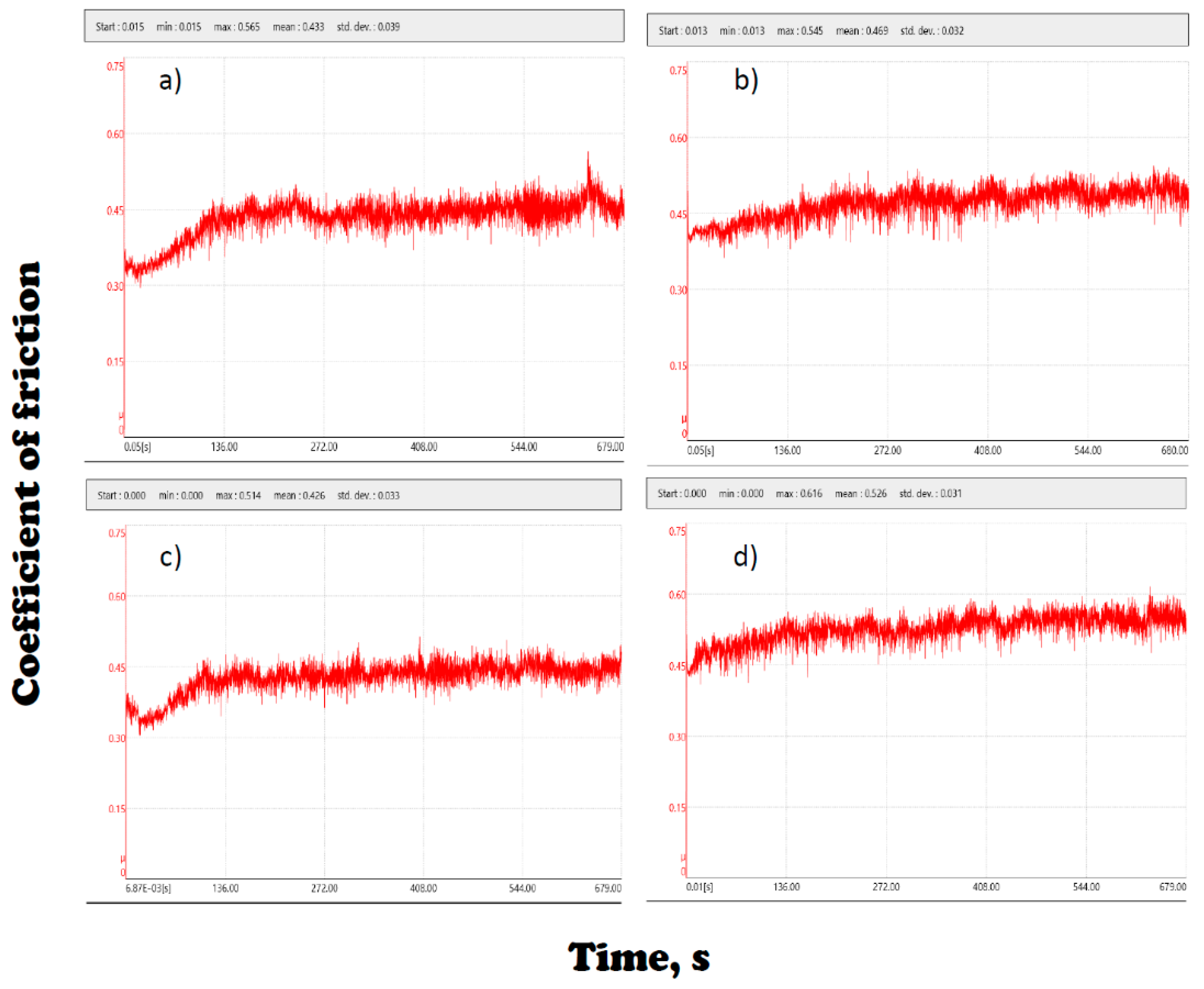
Tribological tests were carried out on samples of selected materials selectively laser sintered on both the lateral surface and the frontal surface on which the laser beam acted. The tests were performed using the ball-on-disc method, as a counter specimen using a tungsten carbide ball with a diameter of 6 mm. The atmosphere of Ringer’s solution was used at 100% humidity and 25 °C. The linear speed was 15 cm/s and the measuring distance was 100 m.
Tests of corrosion resistance of the Ti6Al4V alloy were carried out on specimens gridded on paper with granulation up to 500, and then degreased in acetone. A potentiostat and a glass electrolyte cell were used for corrosion tests.
The measuring system consisted of three electrodes:
working electrode—tested material;
chlor-silver chloride reference electrode with potential 207 mV (at 25 °C);
auxiliary electrode—platinum wire.
Corrosion tests were carried out in two stages:
determination of open circuit potential (Eocp) for 1 h;
recording of anode polarization curves from the potential of Estart = Eocp - 100 mV until the potential reaches 2 V or reaches a current of 1 mA/cm2, with a potential increase of 1 mV/s, followed by registration of the return curve in the Estart potential.
The results were recorded as curves. Then, using the Tafel method, the characteristic electrochemical values of materials were determined:
ikor—anode current density;
Ekor—corrosion potential;
Rpol—polarizing resistance.
The tests were carried out at an ambient temperature in various aquatic solutions given in
Table 4:
saline solution (artificial saliva prepared according to Fusayama’s recipe);
Ringer’s solution with the addition of 30% H2O2;
Ringer’s solution with 1% concentrated acetic acid;
Tyrod’s solution.
The biological research was realised using human osteoblast cells from the hFOB 1.19 (Human ATCC-CRL-11372) culture line according to the authors’ own work [
21]. Cell culture was made in a six-well polystyrene standard plate from Thermo Scientific Nunc Cell Culture Plastics (Roskilde, Denmark). The polystyrene bottles were incubated at 33.5 °C in an atmosphere containing 95% air and 5% CO
2. The cells were etched using trypsin for their separation from the surface. The medium consisted of one part Dulbecco’s modified Eagle’s medium (DMEM) without phenol red and one part Hanks F12 medium. The medium was mixed with L-glutamine (2.5 mM), sodium pyruvate (0.5 mM), gentamicin sulfate (0.3 mg/mL), foetal bovine serum FBS (10%) and 4-(2-hydroxyethyl)-1-piperazineethanesulfonic acid (HEPES, 15 mM). The obtained cells were rinsed and mixed with the medium receiving working suspensions with 2.5 × 10⁵ osteoblasts/mL. Then, 3 mL of the cell working suspension were added to one well with a flat bottom plate. Plates with cells and test materials were incubated for 72 h controlling cells growth after 24, 48 and 72 h. After 72 h of culture, 300 µL of MTT (3-(4.5-dimethylthiazol-2-yl)-2.5-diphenyltera-zolium bromide) solution (5 mg/mL) were added to the medium and incubated for 4 h. NAD(P)H-dependent cellular oxidoreductase enzymes reflected the number of viable cells present. Those enzymes reduced the tetrazolium dye MTT (3-(4.5-dimethylthiazol-2-yl)-2.5-diphenyltera-zolium bromide) to its insoluble formazan with a purple colour. The formazan was dissolved in dimethyl sulfoxide (DMSO) added to the well in a volume of 3 mL after removing culture medium. The flasks were shaken for 10 min. The portion of 150 µL for absorbance measuring was placed in the wells with a flat bottom of a 96-well microplate made of polypropylene. During the culture, photos of the bottoms of the plate at the edge of the material with the cells examined were made in the inverted microscope Olympus IX51 (Tokyo, Japan) with ColorView II Soft Imaging System Cell F (Muenster, Germany) using a magnification of 100×. Absorbance was measured at a wavelength of 550 nm using the Eon High-Performance Microplate Spectrophotometer (BioTek Instruments, Inc., Winooski, VT, USA). Eon’s monochromator-based optics allowed for flexible, filter-free 200–999 nm wavelength selection in 1 nm increments. Eon was aided by Gen5 2.0 Data Analysis Software.
From the obtained absorbance results, the value obtained for pure DMSO was subtracted and the percentage of cell viability was calculated for cells cultured without the materials tested using the following formula:
The results were analysed statistically on the basis of eight specimens in each case. In each case, the standard deviation was calculated, Snedecor’s F-test and Student’s t-test were used, and the significances of differences between means were determined.
4. Test Results of Mechanical Properties Solid Laser-Sintered or Machined Ti6Al4V Alloy
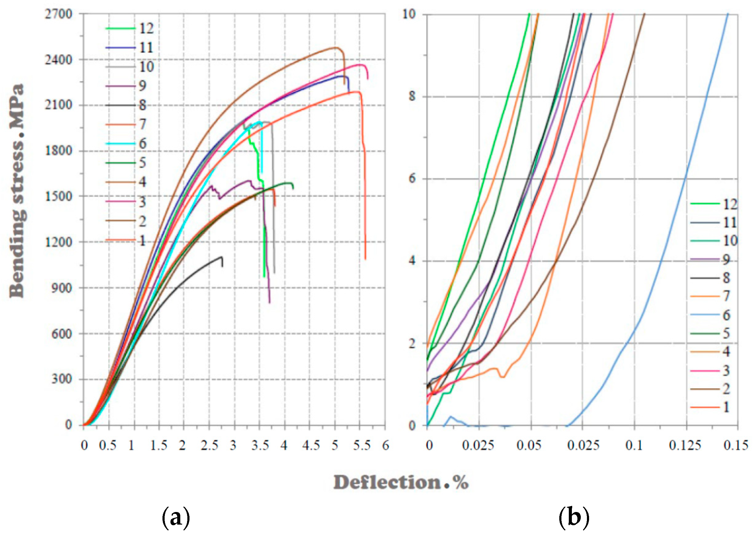
The results of tests on the mechanical properties of solid laser sintered Ti6Al4V alloy, taking into account the various manufacturing conditions, are shown in
Figure 7.
Figure 7a illustrates the full course of the tensile curves in full range, while
Figure 7b shows the initial fragment of these charts at a significant magnification.
The laser power that was used to manufacture the specimens had the highest impact on increasing the tensile strength
. The higher the laser power used, the higher the tensile strength results. The most significant increase in tensile strength occurs when using a 120 µm laser beam width, where an increase in power from 60 to 110 W caused more than a two-fold increase in tensile strength (
Figure 7a).
For a laser beam width of 80 µm, the increase in laser power from 80 to 110 W no longer gives such a spectacular increase in tensile strength, because it is about 150 MPa (
Figure 8a). Changing the laser path width with the same laser power no longer significantly affects the tensile strength. However, with the right laser beam width for each laser power it is possible to achieve the maximum tensile strength for given production conditions from 830 MPa for 60 W to over 1150 MPa for 110 W, which corresponds to an increase in tensile strength by approx. 350 MPa (
Figure 8b).
Table 5 summarizes the statistically averaged results of the tensile strength test depending on different manufacturing conditions, as well as compares them with the results of the bending strength test. The confidence interval in each case is not higher than 5%. The table shows the blue variant solid Ti 4 providing the highest tensile and bending strength values, while the red solid Ti 8 variant providing the lowest amounts of those strengths is given in red.
The value of bending strength of Ti6Al4V micro specimens manufactured at different laser path widths of 40, 60, 80 and 120 μm is strongly dependent on the power of the laser acting on the powder (
Figure 9 and
Figure 10).
Figure 10a presents graphs of the dependence of bending strength on the laser power of specimens manufactured at different laser path widths of 60, 80 and 120 μm. At 60 W laser power, the bending strengths obtained are the lowest compared to other laser powers. Bending strength above 2000 MPa can be purchased for the remaining laser powers.
Increasing laser power is the most crucial factor in improving bending strength. For a laser beam width of 120 µm, increasing the laser power from 60 to 110 W increases the strength by almost 1400 MPa. Another important factor influencing the improvement of bending strength is the width of the laser beam. Within the same laser power, it is possible to select the width of the laser beam, enabling an improvement in bending strength in the range of 336–599 MPa (
Figure 10b).
With a laser power of 60 W and a beam width of 120 μm, the energy emitted by the laser is not sufficient to properly sinter the powder on which the laser acts; therefore, under these conditions, the bending strength of the manufactured specimen is the lowest. At the same laser power of 60 W, narrowing the laser beam width to 60 µm generates energy with a higher energy density, which consequently increases the degree of powder remelting and increases bending strength. The use of a smaller width of the laser beam to the operating energy at a given power also means that the strength of the specimen decreases, however, not as much as when using a larger width of the laser path. For each of the selected laser powers, other manufacturing conditions (mainly the laser beam width) can be chosen in such a way to obtain a sufficiently high bending strength.
Taking into account the different conditions for producing solid specimens from Ti6Al4V alloy by SLS, it is possible to select the required set of strength properties. By changing the diameter of the laser spot, the width of the laser path, the allowance associated with the overlap of individual laser paths, and above all the laser power, it is possible to obtain a material with almost twice the strength compared to material manufactured under other conditions. These results were compared with the tensile and bending strength of the Ti6Al4V alloy machined at the FANUC CNC milling centre (Robodrill S), because such a technology is still most commonly used in implant prosthetics for the production of dental implants and dental abutments. Tensile strength values of 858 MPa were obtained for the Ti6Al4V casting alloy and 1959 MPa for bending. In the case of tensile strength, it is 300 MPa less than in the case of a selective laser sintered alloy, while in the case of bending strength it is even smaller by more than 500 MPa. Using SLS technologies and ensuring appropriate manufacturing conditions, solid material with significantly better strength properties than the casting alloy can be obtained (
Figure 11). Although it dealt with the same material only manufactured differently, the characteristics of both the tensile and bending curves are definitely different. The material manufactured conventionally (i.e., casting) and processed on a CNC milling machine has the characteristics of plastic material; this type of bending and the tensile curve are characteristic for materials with plastic properties. In contrast, sintered material exhibits the properties of brittle materials. The bending stress for the sintered material in the first phase of the test increases strongly with a small deflection to drop sharply when the maximum value is reached; in the case of the tensile curve when the maximum amount is reached, the specimen breaks and the force drops to zero. In the case of plastic materials, when a certain force is reached, the force increases rapidly with a small degree of deformation of the specimen. There is a small increase in force with a large increase in deflection in the case of bending and elongation in the case of tensile.
5. The Structure of the Ti6Al4V Alloy Machined at the CNC Centre and Manufactured by the Selective Laser Sintering Method
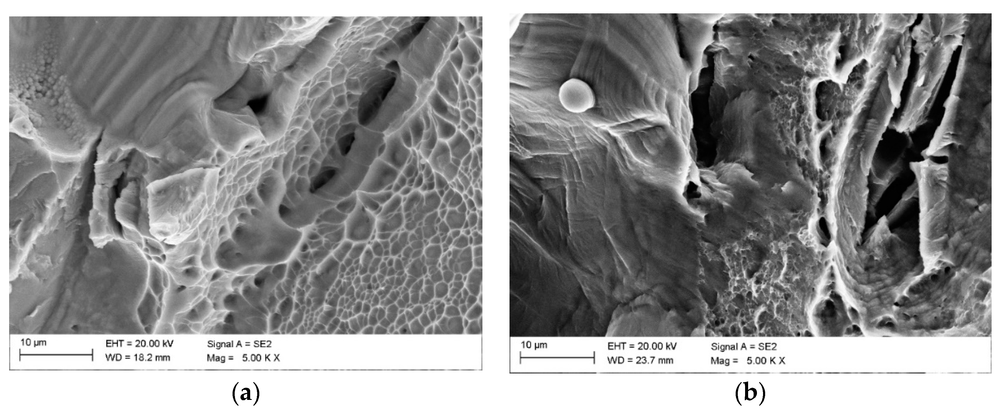
Figure 12 shows the morphology of fractures observed in the scanning electron microscope of the Ti6Al4V casting alloy in the form of cast discs intended for milling in the CNC milling centre and sintered alloy using the SLS method after static bending tests. A breakthrough in casting alloy is plastic and sintered alloy brittle.
Furthermore, the fracture analysis does not indicate significant pores or gas bubbles resulting from the casting process. It can, therefore, be concluded that the share of pores in casting alloys is relatively small.
For comparison, the share of pores in the casting material was also examined (
Figure 13) and compared with a selective laser sintered alloy (
Figure 14). The percentage of pores on the surface of the casting alloy is 0.03%. This type of material is considered solid. Therefore, it can be stated that by using SLS technology, it is possible to manufacture solid materials that are qualitatively comparable to those manufactured by casting technologies.
Metallographic tests on non-etched specimens to assess roughness were carried out by quantitative metallographic methods using Leica’s DMI8A automated light microscope software. The surface share of pores on non-etched metallographic specimens at 100× magnification corresponds to the percentage of the total area occupied by the dark spots that represent the free spaces inside the material. Performing such tests, it can be stated that by using appropriately selected production conditions by the SLS method, one can obtain a material with excellent strength properties but also with inferior properties.
Figure 15 gives examples of porosity assessment in selectively sintered laser specimens according to the options given in
Table 3.
The porosity of the specimen with the most strength is in the range of 0.1%, and that of the least strength is over 10%. Increasing the porosity to more than 10% caused over a two-fold decrease in both tensile and bending strength, and the surface of the specimen has evenly spaced, large-sized pores. In the case of the Ti solid 4 specimen, the porosity is very low (
Figure 14).
In the image of the surface, pores appear in a minimal amount, and the surface is almost uniformly smooth (pores in the material occur sporadically and are low). Increasing the pores’ density to 0.2% of the surface area for the Ti solid 1 sample reduces the bending strength by about 250 MPa; the pores are still very small, but evenly distributed in the material. The surface of the material is no longer as homogeneous as in the case of the Ti solid 4 specimen. Along with the decrease in the strength of the specimens, much larger pores begin to appear in the material. Still, their share in relation to the volume of the entire specimen is small (
Figure 15), and the surface of the specimen is relatively uniform with small places of larger pores.
The appearance of such pores in the material and increasing their share relative to the solid surface to a value of about 1.5% gives a reduction in strength relative to the specimen Ti solid 4 by almost 450 MPa. The measurement of porosity was made for subsequent specimens and Ti solid 5, 7, and 9 showed bending strength at a similar level; the difference in strength between these three specimens was only 80 MPa. In addition, the measured porosity does not differ much—by about 1.5%—and ranges from about 5% to over 6%. In those specimens, a much more significant number of large pores begins to appear, and the surface of the specimen is very heterogeneous, which results in a decrease in the strength of those specimens relative to those with the most strength by up to 800–900 MPa.
Detailed tests on the light microscope and in the scanning electron microscope indicate that the main reason for such significant porosity in the SLS Ti solid 8 variant, with the highest porosity in all the analysed cases, is incomplete sintering and the presence of fine non-sintered particles in individual pores (
Figure 16).
It significantly affects the deterioration of the strength properties of such specimens. In other cases of porosity more significant than 4%, no such effects were found. It was confirmed that sintering takes place with the participation of the liquid phase and has the characteristics of liquid phase sintering (LPS), as in the case of 90% of sintered materials [
97,
98,
99,
100].
Materialographic tests of the selectively sintered material enabled the assessment of the quality of the specimens manufactured by assessing the additive laser transition paths manufactured on the surface and by assessing free spaces in fracture structures and the presence of loose powder particles. It turned out that the set of conditions for SLS recommended by the machine manufacturer defaults do not guarantee satisfactory results with minimal porosity, which justified the need for the detailed structural analysis described below.
Comparing the surface structure of the Ti6Al4V alloy manufactured using different SLS manufacturing conditions after passing the laser, a significant difference can be seen in the surface structure between particular specimens.
Specimens with a homogeneous surface included clearly marked laser paths; where it is possible to measure them (the paths are straight), the specimens are from sets with numbers Ti solid 1 and 4 (
Figure 17 and
Figure 18). The structure described ensures the highest possible values of tensile and bending strength. Specimens’ surface from sets with numbers Ti solid 8 and 5 (
Figure 19 and
Figure 20) are characterized by the presence of free, empty spaces between the laser paths. The laser paths do not overlap, which is consequently reflected in the lowest properties among all tested variants.
Compared to the previously described specimens with the correct structure, this ensures significantly lower strength properties.
A detailed fractography analysis of fractures of specimens destroyed in the results of static tensile and bending tests was also carried out. Specimens with high strength are characterized by a homogeneous structure, and there are no closed pores and no visible grains of sintered powder particles (
Figure 21 and
Figure 22), which of course would reduce the strength. For specimens with much lower strength, the fracture structure is heterogeneous, and between the sintered material fragments, there are free spaces that form closed pores. In many places, there are particles of powder which are not sintered (
Figure 23 and
Figure 24). All this directly affects the density and strength of those samples.
7. Final Remarks
The purpose of this paper is to compare in repeatable conditions the effects of manufacturing prosthetic restorations by the method of milling solid discs with those manufactured using SLS, as the most commonly used method in dentistry additive manufacturing technology. According to the manufacturing conditions recommended by the manufacturer of the SLS device, the so-called defaults do not ensure optimal properties of manufactured products. The authors’ own technological practice also indicates that depending on the technological conditions used during the process, it is possible to obtain a very diverse range of materialographic structures of manufactured products, from entirely correct ones characterized by a practical lack of porosity to those in which the proportion of pores resulting from manufacturing errors exceeds even 10%, which significantly reduces strength properties by up to several dozen percent compared to those manufactured correctly. Positive results of these activities are aimed at convincing dentists about the lack of danger resulting from the use of modern additive technologies, and even the benefits. An unquestionable advantage is the full possibilities of making personalized prosthetic restorations adapted to the anatomical conditions and the condition of each patient’s dental defects. The application of such a modern approach in conjunction with techniques for imaging the patient’s dentition using cone-beam computed tomography (CBCT) and computer-aided design (CAD) is the basis for digitisation at the Dentistry 4.0 stage following the assumptions of the extended holistic Industry 4.0 model. It ensures very high standards of dental care for patients, and in the engineering aspect, maintaining very high-quality standards and tight dimensional tolerances of manufactured prosthetic restorations. It alleviates the anxiety of dentists, who are invariably responsible for the effects of treatment and relationships with patients.
Among metals, titanium and its alloys play the most crucial role in the production of implants, including dental ones and scaffolds. Titanium is particularly suitable for the production of additive methods, especially SLS. Titanium is also used in dental prosthetics, among others due to relatively low density. The disadvantage is the reaction of porcelain with titanium oxide, which causes bruising and darkening of the colour, which can be effectively counteracted by applying appropriate surface layers, most preferably using the atomic layer deposition (ALD) method. This issue is the subject of further own research and is not covered in this paper. While this problem is significant when manufacturing bridges and crowns, it does not exclude the use of titanium and its alloys for the production of implants replacing parts of the root of teeth and abutments.
Titanium alloys have the most significant practical significance, and among them, the Ti6Al4V alloy is the most commonly used. This alloy, known as titanium Grade 5, has a positive reputation among dentists due to its high usefulness in prosthetics and dental implantology. The paper presents the authors’ own examples of using this alloy on various devices used in prosthetics and dental implantology. It includes comparative studies of the structure and properties of the Ti6Al4V alloy used for dental prosthetic restorations made alternatively using the loss method by milling on numerically controlled milling machines and the SLS method.
Selective laser sintering technology commonly called three-dimensional (3D) printing uses a powder with appropriate properties (i.e., grain sizes up to 45 μm, with the spherical particles form), obtained as a result of gas atomisation, as the input material. Such a powder treated with an appropriate set of technological conditions characteristic of SLS technology is transformed into a suitably designed shape. It requires the prior diagnosis of the condition of the patient’s dentition using cone-beam computed tomography (CBCT) methods, as well as intraoral or less often extraoral scanning of properly made impressions and individual design of the required implant-prosthetic components. It is necessary to use highly specialised computer-aided design/manufacturing (CAD/CAM) software. The methodology of this action is described in detail in the authors’ other publications.
The research results contained in this paper indicate that obtaining the right structure, especially a negligible share of pores below 0.1%, requires the selection of numerous selective laser sintering factors that determine the proper choice of technological conditions. In the case of classic sintering, it is necessary to correctly select the appropriate temperature, pressure and sintering time in quite narrow ranges for a powder with specific chemical composition and size. It ensures an optimal structure with minimal porosity providing the most favourable strength properties. In the case of selective laser sintering, the number of these factors is much more. The obtained test results confirm that sintering occurs with the participation of the liquid phase and has the characteristics of liquid phase sintering (LPS). From this statement and the theoretical premises of powder engineering, it is clear that it is not justified to distinguish selective laser sintering (SLS) and selective laser melting (SLM) as separate processes. Sintering is an essential stage of powder engineering with powder metallurgy as its part. In 90% of sintered materials, the LPS decides on the connection of individual powder particles during sintering and in this sense is the essence of sintering. Melting is, therefore, an essential element of sintering processes, and thus distinguishing it from them has no justification; it only introduces terminological confusion and information chaos. Many factors determine the provision of the desired structure and the expected mechanical and functional properties of selective laser sintered materials. The diameter of the laser spot, the width of the laser path, the allowance related to the overlap of individual laser paths, and above all the laser power, as well as the scanning speed, powder layer thickness, statistical size distribution and its bulk characteristics, determine the possibility of obtaining different structure and product properties made this way. SLS technology, while ensuring the right manufacturing conditions, allows for manufacturing solid material with strength properties significantly better than the cast alloy. Despite the identical chemical composition and significantly limited admixture concentrations, both materials behave differently undergoing plastic deformation under static tensile and bending tests. It is also confirmed by the results of fractography analysis of breakthroughs. The conventionally cast material has characteristics specific to plastic materials, with a lower maximum stress value on the tensile and bending curves, respectively, while the elongation or deflection is significantly higher. In the case of material produced by selective laser sintering, the opposite is the case; because the breakthrough is brittle, the maximum stress is significantly higher, and the maximum deformation is much lower. Tensile strength values of 858 MPa were obtained for the Ti6Al4V cast alloy and 1959 MPa for bending. In the case of tensile strength, it is 300 MPa less than in the case of a selective laser sintered alloy, while in the case of bending strength it is even lower by more than 500 MPa. The analysis of the relationship between the production conditions by selective laser sintering and porosity and morphology indicates that the proper selection of those conditions and a sharp technological regime of compliance with them throughout the whole process may lead to the manufacturing of a material with strength almost twice as high as material manufactured under extremely improper conditions. In the case of tensile strength, the maximum value for a correctly carried out process exceeds 1150 MPa, and bending is around 2465 MPa; improperly manufactured material may have a tensile strength that is over twice lower and bending strength that is almost 2.5 times lower. A similar situation is in the tensile case. The main reason is the improper sintering process, especially the local lack of LPS processes visible at the breakthroughs and the occurrence of sintered powder particles and associated local emptiness. It significantly affects the unacceptable increase in porosity, which varies almost 100 times depending on the technological variant. In the variant of obtaining a solid material, the porosity is less than 0.1%, and in the worst variants, it exceeds even 10% of the surface area of the pores. Materials manufactured by this method may ultimately differ significantly in their properties, despite the fact that in each of the discussed cases it is possible to solidify the material. Changing the laser power is crucial. If the power or actually the sintering energy density, which is related to the simultaneous selection of the diameter of the laser spot and the width of the laser path, is reduced, this leads to a situation in which the powder is either “burned” when the power and density of the laser power are too high or the powder is “unburned” when the power is too low compared to optimal standards. It is important to correctly select the technological conditions of the process so as to guarantee the best strength properties. Any change in those conditions is significant. One should be aware that failure to comply with the assumed technological regime even with respect to one or several layers of powder with thickness of 25 μm of each one may cause a discontinuity in the structure and failure to achieve the expected properties. Furthermore, it cannot be assumed that the device can operate in the plug-and-play standard using the settings indicated by the manufacturer, because the research reported in this paper, as well as the authors’ own experiences obtained using other selective laser sintered materials, do not confirm this possibility. The properties of elements manufactured in this way are characterised by properties reduced by up to several dozen percent. Each time the shape and technological process of the manufactured product should be properly designed to ensure proper quality, the required tight dimensional tolerances and maintain high standards. At the same time, depending on the size of the manufactured element’s desired surface structure and the range of permissible porosity, individual process conditions depend. The operator’s experience and the assumptions originally adopted are decisive in this respect.
The tests carried out in the framework of this paper also confirm that it is possible to obtain high abrasion resistance and high corrosion resistance in solutions simulating body fluids, which has also been confirmed to depend on porosity. High properties characterise materials made under conditions preventing porosity higher than 0.1%. The biological properties of the selective laser sintered Ti6Al4V alloy were also checked. It is a good material for implanting osteoblast cells, better than pure titanium, which provides the possibility of using this alloy made with the use of additive technology for implants and implant-scaffolds used in dentistry.
This paper compares the results of testing the structure and tensile and bending strength of the Ti6Al4V selective laser sintered and casting machined in the CNC milling centre of the company FANUC (Robodrill S) because this technology is still most commonly used in implant prosthetics for the manufacturing of implants and dental abutments. The use of the additive manufacturing methods for the manufacturing of prosthetic elements of the Ti6Al4V alloy in combination with the digitisation of dental diagnostics and computer-aided design/manufacturing (CAD/CAM) in accordance with the idea of Dentistry 4.0 is the best choice of technology for the manufacturing of implant and prosthetic devices used in dentistry with the best strength, repeatable in shape and shape compliant with the project and requiring practically no additional post-production operations.


