Article

Thermal and Torrefaction Characteristics of a Small-Scale Rotating Drum Reactor

by
Nitipong Soponpongpipat
*,
Suwat Nanetoe
and
Paisan Comsawang
Department of Mechanical Engineering, Faculty of Engineering and Industrial Technology, Silpakorn University, Nakhon Pathom 73000, Thailand
*
Author to whom correspondence should be addressed.
Processes 2020, 8(4), 489; https://doi.org/10.3390/pr8040489
Submission received: 18 March 2020 / Revised: 16 April 2020 / Accepted: 18 April 2020 / Published: 22 April 2020
(This article belongs to the Special Issue Biomass Processing and Conversion Systems)

Abstract

:
The small-scale rotating drum reactor (SS-RDR) was designed and constructed without using purge gas for the purpose of household application. The thermal and torrefaction characteristics of SS-RDR were studied and compared with other reactor types. It was found that the heat loss at the reactor wall and heat loss from exhaust gas of the SS-RDR were in the range of 6.3–12.4% and 27.9–42.8%, respectively. The increase of flue gas temperature resulted in the decrease of heat loss at the reactor wall and the increase of heat loss from exhaust gas. The heating rate of the SS-RDR was in the range of 7.3–21.4 °C/min. The higher heating value (HHV) ratio, mass yield, and energy yield ofthe SS-RDR were in the range of 1.2–1.6, 35.0–81.0%, and 56.2–96.5%, respectively. A comparison of torrefaction characteristics of various reactor types on HHV ratio-mass yield-iso-energy yield diagram indicated that the torrefaction characteristics of the SS-RDR were better than that of the rotating drum reactor with purge gas.

Graphical Abstract

1. Introduction

At the present time, biomass has a high potentiality as a renewable energy source. However, raw biomass has some drawbacks: high moisture content, low heating value, low density and a high degree of biodegradation. The torrefaction process, a thermochemical reaction for an improvement of raw biomass, is a reliable technology for upgrading the properties of biomass fuel. The temperature for the torrefaction process is controlled in the range of 200–300 °C under an inert atmosphere [1,2,3]. There are many types of torrefaction reactor such as fixed bed, moving bed, fluidized bed, and rotating drum reactor. Based on the heat transfer mechanism from heat source to biomass, these reactors can be divided into two groups including direct and indirect heating [4]. For the direct heating reactor, a heating medium with either a small amount or no oxygen is used to avoid biomass combustion. Examples of heating mediums are superheat steam, flue gas, inert gas, and hot solid particles. The outstanding advantages of the direct heating reactor are a high heat transfer rate and uniform heat transfer. Its drawbacks are the difficulty controlling the amount of oxygen content in the case of flue gas, and the high cost of the gas generator and heat recovery system in the case of superheat steam and inert gas. For the indirect heating reactor, heat transfers through the reactor wall to biomass. Thus, it is not necessary to control the amount of oxygen in the heating medium. The heat transfer rate of the indirect heating reactor is lower compared to that of the direct heating one. The rotating drum reactor is a proven technology applied in a wide range of uses, from biomass drying [5] to torrefaction. The rotating drum torrefaction reactor can be used in both direct [6] and indirect heating [7,8,9]. The direct heating rotating drum with N2 as purge gas is usually found at a laboratory scale. Pawlak-Kruczek et al. [10] investigated the process characteristic of the batch-wise isothermal rotary reactor with palm kernel shells, olive waste, wood chips, and rapeseed straw as feedstock. N2 was used as purge gas. The obtained mass and energy yield were in the range of 50–87% and 65–95%, respectively. Dhungana et al. [4] compared the mass and energy yield obtained from three types of reactor including the convective bed, fluidized bed, and rotating drum. The rotating drum gave the lowest mass and energy yield compared to other reactors. Soponpongpipat et al. [11] compared various reactor types on Higher Heating Value (HHV) ratio–mass yield–iso-energy yield diagram. The HHV ratio of torrefied char produced by the rotating drum reactor was the lowest compared to that of other reactors at a similar energy yield. In addition, the difference in properties of torrefied char obtained from different atmospheres (N2 and without N2) was also reported. Torrefaction without N2 resulted in a higher HHV ratio at the same energy yield. Mok et al. [12] conducted biomass pyrolysis in a sealed reactor. The water vapor, produced from biomass pyrolysis, was an autocatalyst for cellulose degradation reaction and conducted the decrease of reaction onset temperature resulting in a higher charcoal yield. These results indicate the effect of pyrolysis atmosphere on char properties. In terms of the energy balance of the reactor, there were studies on the energy balance of the torrefaction reactor. Kuzmina et al. [13] analyzed the energy efficiency of the direct heating torrefaction reactor. Director et al. [14] conducted the numerical analysis of a reactor with recirculation of the heat carrier. However, studies on the energy balance of the rotating drum reactor are rarely found. According to a literature survey, studies on energy balance of the rotating drum were found in other applications, i.e., the cement rotary kiln [15,16]. The rotating drum reactor had a capacity in the ranges of 1–10 kg/h, 100–500 kg/h [10], and 1.5–4.5 Mg/h [7] for laboratory, pilot and large-scale production, respectively. In commercial, the rotating drum forrefaction reactor with continuous feed was usually used. Although batch-wise torrefaction using the rotating drum reactor was not suitable at a commercial scale, it was useful for torrefied char production at a household scale in rural areas. In this case, a simple structure design and free using of N2 were required.
Although there were many reports on the effect of torrefaction atmospheres on the properties of torrefied char, most of these works were conducted by a laboratory-scale reactor. Torrefaction of oil palm kernel shells in the presence of oxygen and carbon dioxide was reported. The presence of these gases resulted in a slight decrease of solid yield [17]. Non-oxidative and oxidative torrefaction of fibrous and ligneous biomass were also conducted. The increase of O2 concentration resulted in the decrease of solid yield. The non-oxidative torrefaction had a better performance than oxidative torrefaction [18]. The opposite result was reported for torrefaction of sawdust with purge gas containing 3–6% O2. The presence of O2 had no effect on the properties of torrefied char [19]. Previous studies at the pilot scale, i.e., the thermosyphon-fixed bed reactor (TSFR) indicated the better properties of torrefied char obtained from torrefaction in a purge gas (N2)-free atmosphere. However, the biomass particle arrangement inside the TSFR was in the form of compact bulk. For the rotating drum reactor, the biomass particle arrangement was in the form of hollow bulk and there is no certainty of evidence on the comparison of torrefied char’s properties obtained from different atmospheres (N2 and without N2). The literature survey revealed the gap in characteristics of torrefied char obtained from rotating drum reactor without using N2 as purge gas. Moreover, the report on the energy balance and range of the heat loss percentage of the rotating drum as torrefaction reactor was insufficient. Although the range of the heat loss percentage can be estimated from a previous report on cement kiln applications, the effect of heat source temperature on heat loss was not reported. For torrefaction applications, variation of heat source temperature was necessary to achieve the desired heating rate. Understanding of heat balance and heat loss in the rotating drum torrefaction reactor at various heat source temperatures (in other words, flue gas temperature) led to a reactor design and process operation with high thermal efficiency. In this work, the batch-wise rotating drum reactor (SS-RDR) was constructed without using N2 as purge gas. The heat loss and heating rate of the SS-RDR at various flue gas temperatures were investigated. In addition, the properties of torrefied char obtained from the SS-RDR were investigated and compared with those obtained from the other reactor types using a HHV ratio–mass yield–iso-energy yield diagram.

2. Materials and Methods

2.1. Biomass Sample

Sawdust was used in this experiment. It was gathered from Nonthaburi (13°55′38.4″ N 100°23′40.2″ E). The particle size distribution of the sample was determined by sieve analysis according to the ASTM E11 (1989) standard. The average particle size of the sawdust was 5 mm. The moisture content of the raw sawdust was controlled in the range of 5 ± 1% (w.b.). It can be determined by the method of ASTM D3173-87.

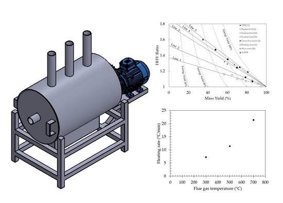
2.2. Small-Scale Rotating Drum Reactor

Figure 1 shows the small-scale rotating drum reactor (SS-RDR) constructed in this work. This reactor was divided into two parts; rotating drum and shell. The rotating drum installed inside the shell was made from ASTM A-36 steel with a diameter of 0.35 m and a length of 0.80 m. There was a vent tube at the lid of the drum to ventilate volatile produced from torrefaction. The steel shell had a diameter of 0.60 m and a length of 0.90 m. Ceramic fiber with a thickness of 0.05 m was used as a thermal insulator. It was installed on the inner surface of the shell. The gap between the rotating drum and the insulator was used as flow channel of flue gas produced from combustion of the heat source. There was an opening of 0.15 m × 0.75 m at the bottom side of shell wall to receive flue gas. To investigate the heat loss and heat transfer mechanism between flue gas and the reactor clearly, flue gas had to be produced with uniform temperature and composition. In this case, biomass combustion to produce flue gas was unsuitable. Thus, a liquid petroleum gas (LPG) burner was used as the heat source. Flue gas produced from LPG combustion flowed through the opening to the flue gas flow channel and left the reactor at three stacks located at the top side of the shell. This flow configuration resulted in heat transfer from the flue gas to the rotating drum wall and, consequently, heat was transferred from the wall to the biomass inside the drum.

2.3. Experimental Procedure

The procedure for the investigation of the thermal characteristics of the reactor was as follows. Firstly, the 4 kg of raw sawdust were loaded into the rotating drum. The volume of filled sawdust was approximately 50% of the drum volume. Then, the drum lid was closed to prevent the sawdust from mixing with the outside air. Later, the shell lid was closed to force the flue gas to leave the shell at the three stacks. Then, the drive motor was started in order to rotate the drum. The rotating speed of the drum was controlled at 3.75 revolutions per minute (RPM). After the drum rotation was steady, the LPG burner was ignited. The flue gas temperature was monitored by three K-type thermocouples (K1, K2, K3) installed between LPG burner and the shell wall opening (Figure 2). The flue gas temperature was controlled at a set point by adjusting the LPG flow rate. It was noted that heat source in real applications can be obtained from biomass combustion. Its flue gas temperature was in the range of 300–700 °C. Thus, the flue gas temperature was varied at 300, 500 and 700 °C in this work. The sawdust temperatures inside the drum were measured by three thermocouples (K4, K5, K6) to determine the heating rate of the reactor. When the sawdust temperature reached 270 °C, the experiment was over. The outside shell wall temperature was recorded (K7, K8, K9, K10, K11, K12) to calculate heat loss at the shell wall. Flue gas temperatures were recorded (K13, K14, K15, K16, K17, K18) to determine heat loss from exhaust gas. The details of thermocouple installation are shown in Figure 2. The flow rate and chemical composition of the flue gas were measured with a portable gas analyzer. During measurement, the gas analyzer probe was inserted at the middle of the three stacks (P1, P2, P3). Heat loss at the shell wall (Q1) was composed of convection heat loss (Qconv) and radiation heat loss (Qrad), as shown in Equation (1).
Q 1 = Q c o n v + Q r a d
The convection heat loss can be determined by the following equation:
Q c o n v = h A w ( T w T a )
where h represents the convection heat transfer coefficient (W/m2-K) which can be determined by Hilbert’s equation [20], Aw denotes the shell wall surface area (m2), and (Tw − Ta) displays the temperature difference between the shell wall and the ambient air (K).
The radiation heat loss can be calculated by the following equation:
Q r a d = σ ε A w ( T w 4 T a 4 )
where σ denotes the Stefan-Boltzmann constant (5.67 × 10⁻⁸ W/K4m2) and ε represents the emissivity of the shell wall (0.77).
Heat loss from exhaust gas can be determined by the following equation:
Q 2 = ρ A s v f C p ( T g T a )
where ρ displays flue gas density (kg/m3), As represents the cross section area of the stack (m2), vf denotes flue gas velocity (m/s), Cp represents flue gas heat capacity (kJ/kg-K), and Tg denotes flue gas temperature (K).
Heat input (Qin) to the rotating drum reactor can be calculated by the following equation:
Q i n = m f L H V
where mf represents the mass of combusted LPG (kg) and LHV denotes the lower heating value of LPG (45.80 MJ/kg).
To investigate the characteristics of torrefied char obtained from the reactor, the flue gas temperature was controlled at 500 °C to heat 4 kg of sawdust inside the rotating drum. When the sawdust temperature reached the set torrefied temperature, the LPG flow rate was adjusted to maintain the sawdust temperature at this set point. The preliminary experiment indicated that there was a slight change at low torrefaction temperature (220 °C). To clearly investigate the effect of torrefied temperature on torrefied char’s properties, the torrefied temperature was selected at the medium and high temperature. Thus, the torrefied temperature was varied at 260, 300, 340 °C. For each torrefied temperature, the torrefaction time was set at 30 min. After torrafaction was over, torrefied sawdust was left to cool inside the drum until it reached room temperature. The mass of torrefied sawdust inside the drum was weighted and kept in an air-tight plastic bag to determine the HHV. The HHV was measured using a bomb calorimeter in accordance with the ASTM D 5865-07a method. The HHV ratio, mass yield, and energy yield of the process were also calculated by the following equations:
HHV ratio = HHV torrefied   char HHV raw   biomass
Y mass = m torrefied   char m raw   biomass
Y energy = Y mass ×   ( HHV torrefied   char HHV raw   biomass )
where Ymass and Yenergy denote the mass yield and energy yield, respectively. mtorrefied char and mraw biomass represent the mass of torrefied char and the mass of raw biomass at the initial time (kg), respectively; and HHVtorrefied char and HHVraw biomass signify the higher heating value of torrefied char and raw biomass (MJ/kg), respectively.

3. Results and Discussion

3.1. Thermal Characteristics of SS-RDR

The relationship between heat loss and flue gas temperature is shown in Figure 3. The fraction of heat loss at the reactor wall (Q1/Qin) tended to decrease from 12.4% to 6.3% when the flue gas temperature was increased from 300 °C to 700 °C. Compared to previous reports on total heat loss from radiation and convection of the cement rotary kiln surface (5.1%) [15], the value of Q1/Qin was rather high. It indicates insufficient thermal insulation around the reactor shell surface. The decrease of Q1/Qin with the increase of flue gas temperature resulted from the increase of heat loss from exhaust gas. The fraction of heat loss from exhaust gas (Q2/Qin) increased from 27.9% to 42.8% when the flue gas temperature was increased. When the flue gas temperature was increased, the stack draft increased resulting in the increase of flue gas velocity and flow rate. Consequently, a large amount of heat was carried out by exhaust gas through the stacks. Thus, the opposite trend was found between heat loss at the reactor wall and heat loss from exhaust gas. In addition, previous works on cement rotary kiln reported that the exhaust gas heat loss was 25.2% [15] and 19.2% [16] which was dramatically low compared to that of the SS-RDR. It indicates the low heat transfer rate from flue gas to surface area of the rotating drum. For total heat loss, it rapidly increased from 40.3% to 47.7% when the flue gas temperature was increased from 300 °C to 500 °C. This rapid increase displays the low value of useful heat resulting in the slight increase of biomass’s heating rate during the heating period of the torrefaction process (Figure 4). The slight increase of total heat loss from 47.7% to 49.1% was found when the flue gas temperature was varied from 500 °C to 700 °C. In this temperature range, the heat transfer rate to the rotating drum (useful heat) increased due to the increase of flue gas velocity and convection heat transfer coefficient. It was confirmed by the dramatic increase of heating rate from 11.4–21.4 °C/min. Thus, the flue gas temperature range of 500–700 °C is suitable for operating the SS-RDR to maintain a high value of useful heat.
The heating rate of the SS-RDR was in the range of 7.3–21.4 °C/min, which was higher than that of the thermosyphon-fixed bed torrefaction reactor (TSFR) [11] and the laboratory fixed bed reactor [11,21]. Usually, the flue gas temperature of biomass combustion in an ordinary stove or burner is in the range of 300–700 °C. Thus, only slow pyrolysis of biomass (< 30 °C/min [22]) can be conducted by the SS-RDR. To increase the heating rate of the SS-RDR, the heat transfer enhancement between flue gas and rotating drum (in other words the exhaust gas heat loss reduction) is necessary. It can be conducted by the use of an extended surface (fin) at the surface of the rotating drum or the increase of the flow channel length before the flue gas travels to the stacks. Sufficient insulation on the reactor’s shell is also needed to reduce the heat loss at the reactor wall.

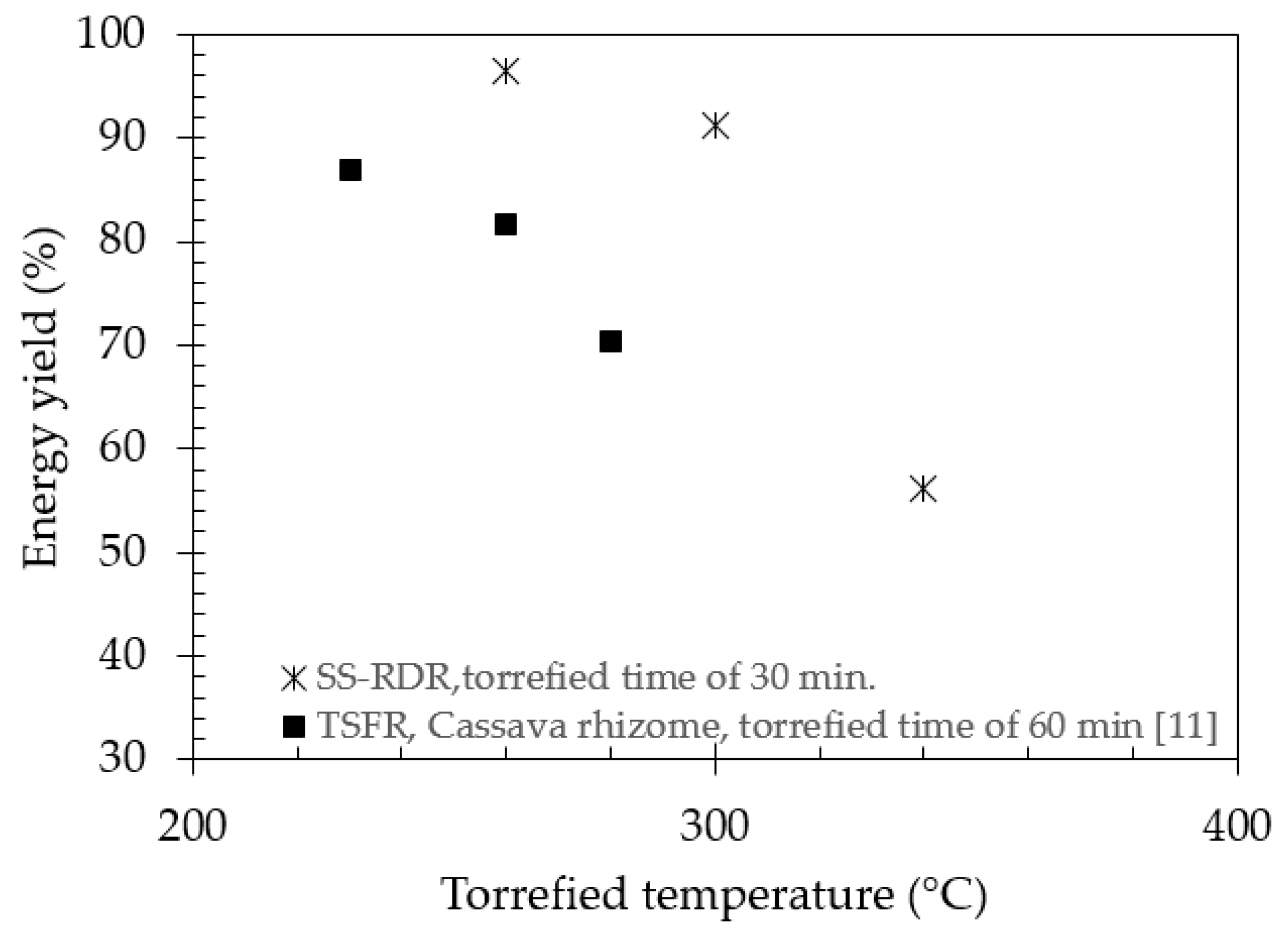
3.2. HHV Ratio, Mass Yield, and Energy Yield

The variation of HHV ratio, mass yield, and energy yield at various torrefaction temperatures is shown in Figure 5. When torrefaction temperature was increased from 260 °C to 340 °C, the HHV ratio of torrefied char obtained from SS-RDR increased from 1.2 to 1.6. This trend is similar to one reported by previous work [11,23]. The increase of HHV indicates a higher degree of biomass degradation during the torrefaction process. The SEM images of previous work [23] displayed a higher degree of biomass decomposition when torrefied temperature was increased. As seen in Figure 5, the increase of torrefied temperature inside the SS-RDR conducted a higher degree of thermal decomposition and HHV ratio. For mass yield, it decreased from 81.0% to 35.0% when torrefied temperature was increased from 260 °C to 340 °C (Figure 6). In fact, the decrease of mass yield has two meanings. The first meaning is mass loss from thermal degradation and the second one is mass loss from biomass drying. The decrease of mass yield together with the increase of HHV ratio indicates biomass thermal degradation. In contrast, the decrease of mass yield without the change of HHV ratio points to biomass drying. The result in Figure 6 indicates that torrefaction can be conducted inside the SS-RDR. For energy yield, it decreased from 96.5% to 56.2% when the torrefied temperature was increased from 260 °C to 340 °C (Figure 7). This trend is similar to one found in the TSFR [11].
To specify a suitable torrefied time and temperature, the highest energy yield and HHV ratio are important criteria. For reactor comparison, energy yield and HHV ratio are still important. As seen in Figure 5 and Figure 7, there is an opposite trend between HHV ratio and energy yield. This was also reported by previous works [4,24,25,26]. Thus, it is difficult to compare the torrefied characteristics of different reactor types by considering energy yield and HHV ratio separately. In addition, the differences in the torrefied condition of each reactor type found in the literature resulted in greater difficulties when comparing the reactor’s performance. To eliminate these difficulties, the HHV ratio-mass yield-iso-energy yield diagram was proposed [11]. Comparison of the SS-RDR and other reactor types is shown in Figure 8. At the equal HHV ratio, the SS-RDR produced torrefied char with the highest energy yield while the other rotating drum reactors [4] produced torrefied char with the lowest one. In the case of the SS-RDR, torrefaction was done without purge gas while the rotating drum reactor in the other study was operated by using N2 as purge gas. This result indicates the effect of purge gas on torrefaction characteristics (HHV ratio, mass yield, and energy yield). For torrefaction without purge gas, volatile produced from biomass degradation during torrefaction had sufficient time to play a role as autocatalyst. In contrast, purge gas suppressed the autocatalyst effect of the volatile [11]. Thus, the different decomposition pathways were obtained when torrefaction was done with different atmospheres.
It is noted that data of biomass torrefaction at the different torrefied temperature rests on the same solid line when biomass is torrefied by the same reactor type (Figure 8). Each solid line displays the different decomposition pathways of biomass [11]. Thus, the torrefaction characteristics of each reactor can be observed clearly by considering each solid line. Solid line 1 and 2 represent the torrefaction characteristics of the rotating drum reactor with purge gas [4], the convective reactor [4], and the fluidized bed reactor [4,24,25]. These reactors had similar torrefaction characteristics because the autocatalyze effect from torrefied volatile was suppressed by purge gas. The solid lines 3–5 display the characteristics of the SS-RDR, TSFR [11], and microwave reactors [26]. The autocatalyze effect contributed to the similar torrefaction characteristics of these reactors. Although the HHV ratio–mass yield–iso-energy yield diagram has a potentiality to identify the torrefaction characteristics of each reactor and to select the best conditions for the torrefaction process, this diagram is a preliminary study. It is necessary to study the effects of torrefied temperature, heating rate, biomass type, and its moisture content on this diagram.

4. Conclusions

The thermal and torrefaction characteristics of a batch-wise rotating drum reactor not using purge gas (SS-RDR) was studied in this work. It was found that the heat loss at the reactor wall and heat loss from the exhaust gas of the SS-RDR were in the range of 6.3–12.4% and 27.9–42.8%, respectively. The increase of flue gas temperature resulted in the decrease of heat loss at the reactor wall and the increase of heat loss from exhaust gas. The heating rate of the SS-RDR was in the range of 7.3–21.4 °C/min which was in the range of the slow pyrolysis of biomass. The heat loss from exhaust gas had a strong effect on heating rate of the SS-RDR. The suitable flue gas temperature for operating the SS-RDR was in the range of 500–700 °C. The HHV ratio, mass yield, and energy yield of the SS-RDR were in the range of 1.2% to 1.6%, 35.0% to 81.0%, and 56.2% to 96.5%, respectively. When torrefaction temperature was increased, the HHV ratio increased while mass yield and energy yield decreased. Comparison with the HHV ratio-mass yield-iso-energy yield diagram indicate that the SS-RDR has better torrefaction characteristics compared to the rotating drum reactor with purge gas. Although this preliminary study of SS-RDR characteristics gave a satisfying result to some extent, the development of the SS-RDR is still necessary. The heat transfer enhancement of the rotating drum surface should be improved. In addition, further studies on the effect of torrefied temperature, heating rate, biomass type, and its moisture content on the torrefaction characteristics of the SS-RDR are needed.

Author Contributions

Conceptualization, N.S. and S.N.; Methodology, N.S., S.N. and P.C.; Software, N.S.; Validation, N.S., S.N. and P.C.; Formal Analysis, N.S.; Investigation, N.S., S.N. and P.C.; Resources, N.S., S.N. and P.C.; Data Curation, N.S., S.N. and P.C.; Writing—Original Draft Preparation, N.S., S.N. and P.C.; Writing—Review and Editing, N.S., S.N. and P.C.; Visualization, N.S. and S.N.; Supervision, S.N. and P.C.; Project Administration, N.S., S.N. and P.C.; Funding Acquisition, S.N. and P.C. All authors have read and agreed to the published version of the manuscript.

Funding

This research was funded by Silpakorn University Research, Innovation and Creative Fund, grant number RD60M2-14.

Acknowledgments

The authors gratefully acknowledge Silpakorn University Research, Innovation and Creative Fund and Department of Mechanical Engineering, Faculty of Engineering and Industrial Technology, Silpakorn University, Sanam Chandra Palace Campus for all support.

Conflicts of Interest

The authors declare no conflict of interest.

References

  1. Bridgeman, T.G.; Jones, J.M.; Shield, I.; Williams, P.T. Torrefaction of reed canary grass, wheat straw and willow to enhance solid fuel qualities and combustion properties. Fuel 2008, 87, 844–856. [Google Scholar] [CrossRef]
  2. Medic, D.; Darr, M.; Shah, A.; Potter, B.; Zimmerman, J. Effects of torrefaction process parameters on biomass feedstock upgrading. Fuel 2012, 91, 147–154. [Google Scholar] [CrossRef]
  3. Deng, J.; Wang, G.; Kuang, J.; Zhang, Y.; Luo, Y. Pretreatment of agricultural residues for co-gasification via torrefaction. J. Anal. Appl. Pyrolysis 2009, 86, 331–337. [Google Scholar] [CrossRef]
  4. Dhungana, A.; Basu, P.; Dutta, A. Effects of Reactor Design on the Torrefaction of Biomass. J. Energy Resour. Technol. 2012, 134, 041801. [Google Scholar] [CrossRef]
  5. Thararux, C.; Kiatsiriroat, T. Drying Strategy of a Rotary Drum Longan Dryer. Int. Energy J. 2003, 4, 105–118. [Google Scholar]
  6. Ribeiro, J.M.C.; Godina, R.; Matias, J.C.O.; Nunes, L.J.R. Future Perspectives of Biomass Torrefaction: Review of the Current State-Of-The-Art and Research Development. Sustainability 2018, 10, 2323. [Google Scholar] [CrossRef] [Green Version]
  7. Nhuchhen, D.R.; Basu, P.; Acharya, B. A comprehensive review on biomass torrefaction. Int. J. Renew. Energy Biofuels 2014, 2014, 1–56. [Google Scholar] [CrossRef]
  8. Teal, W.B.; Gobel, R.J.; Johnson, A. Biomass torrefaction system and method. Patent number 0085023 A1, 21 August 2012. [Google Scholar]
  9. Libingson, A.D.; Thomas, B.J. High energy efficiency biomass conversion process. Patent number 8388813 B1, 5 March 2013. [Google Scholar]
  10. Pawlak-Kruczek, H.; Krochmalny, K.; Mościcki, K.; Zgóra, J.; Czerep, M.; Ostrycharczyk, M.; Niedźwiecki, Ł. Torrefaction of various types of biomass in laboratory scale, batch-wise isothermal rotary reactor and pilot scale, continuous multi-stage tape reactor. Inżynieria i Ochrona Środowiska 2017, 20, 457–472. [Google Scholar] [CrossRef]
  11. Soponpongpipat, N.; Nanetoe, N.; Comsawang, P. Thermal Degradation of Cassava Rhizome in Thermosyphon-Fixed Bed Torrefaction Reactor. Processes 2020, 8, 267. [Google Scholar] [CrossRef] [Green Version]
  12. Mok, W.S.L.; Antal, M.J.; Szabo, P.; Varhegyi, G.; Zelei, B. Formation of charcoal from biomass in a sealed reactor. Ind. Eng. Chem. Res. 1992, 31, 1162–1166. [Google Scholar] [CrossRef]
  13. Kuzmina, J.S.; Director, L.B.; Shevchenko, A.L.; Zaichenko, V.M. Energy efficiency analysis of reactor for torrefaction of biomass with direct heating. J. Phys. Conf. Ser. 2016, 774, 012138. [Google Scholar] [CrossRef]
  14. Director, L.B.; Ivanin, O.A.; Sinelshchikov, V.A. Numerical analysis of biomass torrefaction reactor with recirculation of heat carrier. J. Phys. Conf. Ser. 2018, 946, 012037. [Google Scholar] [CrossRef] [Green Version]
  15. Ayu, T.T.; Hailu, M.H.; Hagos, F.Y.; Atnaw, S.M. Energy audit and waste heat recovery system design for a cement rotary kiln in Ethiopia: A case study. Int. J. Automot. Mech. Eng. (IJAME) 2015, 12, 2983–3002. [Google Scholar] [CrossRef]
  16. Engin, T.; Ari, V. Energy auditing and recovery for dry type cement rotary kiln systems––A case study. Energy Convers. Manag. 2005, 46, 551–562. [Google Scholar] [CrossRef]
  17. Saadon, S.; Uemura, Y.; Mansor, N. Torrefaction in the Presence of Oxygen and Carbon Dioxide: The Effect on Yield of Oil Palm Kernel Shell. Procedia Chem. 2014, 9, 194–201. [Google Scholar] [CrossRef] [Green Version]
  18. Chen, W.-H.; Lu, K.-M.; Lee, W.-J.; Liu, S.-H.; Lin, T.-C. Non-oxidative and oxidative torrefaction characterization and SEM observations of fibrous and ligneous biomass. Appl. Energy 2014, 114, 104–113. [Google Scholar] [CrossRef]
  19. Wang, C.; Peng, J.; Li, H.; Bi, X.T.; Legros, R.; Lim, C.J. Oxidative torrefaction of biomass residues and densification of torrefied sawdust to pellets. Bioresour. Technol. 2013, 127, 318–325. [Google Scholar] [CrossRef]
  20. Cengel, Y.A. Heat Transfer—A Practical Approach, 2nd ed.; McGraw-Hill: New York, NY, USA, 2003. [Google Scholar]
  21. Budde, K.P.; Megha, R.; Patel, R.; Pandey, J. Investigating effects of temperature on fuel properties of torrefied biomass for bio-energy systems. Energy Sources Part. A Recovery Util. Environ. Eff. 2018, 41, 1140–1148. [Google Scholar] [CrossRef]
  22. Chen, D.; Zhou, J.; Zhang, Q. Effects of heating rate on slow pyrolysis behavior, kinetic parameters and products properties of moso bamboo. Bioresour. Technol. 2014, 169, 313–319. [Google Scholar] [CrossRef]
  23. Soponpongpipat, N.; Sae-Ueng, U. The effect of biomass bulk arrangements on the decomposition pathways in the torrefaction process. Renew. Energy 2015, 81, 679–684. [Google Scholar] [CrossRef]
  24. Li, H.; Liu, X.; Legros, R.; Bi, X.T.; Lim, C.J.; Sokhansanj, S. Torrefaction of sawdust in a fluidized bed reactor. Bioresour. Technol. 2012, 103, 453–458. [Google Scholar] [CrossRef] [PubMed]
  25. Atienza-Martínez, M.; Fonts, I.; Ábrego, J.; Ceamanos, J.; Gea, G. Sewage sludge torrefaction in a fluidized bed reactor. Chem. Eng. J. 2013, 222, 534–545. [Google Scholar] [CrossRef]
  26. Lin, Y.L. Effects of Microwave-Induced Torrefaction on Waste Straw Upgrading. Int. J. Chem. Eng. Appl. 2015, 6, 401–404. [Google Scholar] [CrossRef] [Green Version]
Figure 1. Structure of small-scale rotary drum reactor (SS-RDR).
Processes 08 00489 g001
Figure 2. Detail of thermocouple installation.
Processes 08 00489 g002
Figure 3. Heat loss at various flue gas temperatures.
Processes 08 00489 g003
Figure 4. Relationship between flue gas temperature and heating rate.
Processes 08 00489 g004
Figure 5. Relationship between torrefied temperature and higher heating value (HHV) ratio.
Processes 08 00489 g005
Figure 6. Relationship between torrefied temperature and mass yield.
Processes 08 00489 g006
Figure 7. Relationship between torrefied temperature and energy yield.
Processes 08 00489 g007
Figure 8. Comparison of the SS-RDR and other reactor types.
Processes 08 00489 g008

