Review

Methodologies for the Design of Solar Receiver/Reactors for Thermochemical Hydrogen Production

Dipartimento di Ingegneria Chimica Materiali Ambiente, Sapienza Università Di Roma, Via Eudossiana 18, 00184 Roma, Italy
*
Author to whom correspondence should be addressed.
Processes 2020, 8(3), 308; https://doi.org/10.3390/pr8030308
Submission received: 4 February 2020 / Revised: 18 February 2020 / Accepted: 4 March 2020 / Published: 7 March 2020
(This article belongs to the Special Issue Modelling and Optimization of Chemical Reactors)

Abstract

:
Thermochemical hydrogen production is of great interest due to the potential for significantly reducing the dependence on fossil fuels as energy carriers. In a solar plant, the solar receiver is the unit in which solar energy is absorbed by a fluid and/or solid particles and converted into thermal energy. When the solar energy is used to drive a reaction, the receiver is also a reactor. The wide variety of thermochemical processes, and therefore of operating conditions, along with the technical requirements of coupling the receiver with the concentrating system have led to the development of numerous reactor configurations. The scope of this work is to identify general guidelines for the design of solar reactors/receivers. To do so, an overview is initially presented of solar receiver/reactor designs proposed in the literature for different applications. The main challenges of modeling these systems are then outlined. Finally, selected examples are discussed in greater detail to highlight the methodology through which the design of solar reactors can be optimized. It is found that the parameters most commonly employed to describe the performance of such a reactor are (i) energy conversion efficiency, (ii) energy losses associated with process irreversibilities, and (iii) thermo-mechanical stresses. The general choice of reactor design depends mainly on the type of reaction. The optimization procedure can then be carried out by acting on (i) the receiver shape and dimensions, (ii) the mode of reactant feed, and (iii) the particle morphology, in the case of solid reactants.

1. Introduction

Hydrogen production through solar-driven processes is of great interest due to the potential for significantly reducing the dependence on fossil fuels as energy carriers. Thermochemical routes for hydrogen production include: solar water thermolysis, water-splitting redox cycles, reforming, cracking, and gasification. The hydrogen source is water for the solar thermolysis and water-splitting redox cycles, fossil fuels for cracking, and a combination of water and fossil fuels for solar reforming and gasification [1]. One of the challenges in the design of solar plants is linked to the simultaneous identification of favorable configurations of both the reactor and the solar concentrating facility. These may be broadly classified as solar furnaces, solar towers, linear Fresnel reflectors, and parabolic trough facilities [2,3]. A solar furnace consists of a heliostat equipped with an automatic Sun tracking system, which reflects the solar radiation on a stationary concentrating mirror. The receiver, which is the unit in which solar energy is converted into thermal energy, is placed at the focal point of the concentrator. These systems are designed to provide highly concentrated radiation in very controlled environments and are ideal for small-scale systems. Solar tower facilities are instead utilized on the industrial scale. Here, a field of heliostats concentrate solar radiation onto a receiver located on top of the tower. An alternative plant design, known as beam down configuration, consists of placing the receiver on the ground rather than on the tower, on top of which a secondary concentrator is instead installed. The main advantages of the beam down configuration are reducing the weight and complexity of the equipment installed on top of the tower [2]. Parabolic trough and linear Fresnel facilities consist of 2D concentrating systems that direct the solar radiation on a receiver installed along their focal line. They are mainly suitable for heat fluids up to 500 °C [3].
The wide variety of thermochemical processes, and therefore of operating conditions, along with the technical requirements of coupling the receiver with the concentrating system have led to the development of numerous reactor configurations. In addition, some groups have found that the receiver may be responsible for most of the energy losses in a hydrogen production process, including the auxiliary units and separation steps, and that these losses can be significantly reduced by improving the design of the reactor [4]. Some reviews may be found in the literature summarizing the proposed reactor configurations for each application. For example, Kodama et al. [5] reviewed particle reactors for solar two-step water splitting with metal oxides and solar gasification. On the other hand, it is often difficult to discern the reason for which one configuration is preferred over others or to understand the methodology that has been and can be followed to improve the design of solar receivers/reactors. In this context, the aim of the present review is to provide a survey of criteria that can be adopted to identify the most suitable receiver/reactor configuration for a given application and methodologies proposed to improve the reactor design. With regards to the latter aspect, specific focus is placed on the identification of the parameters most suitable to quantify the performance of solar receivers/reactors and of the operating conditions and design variables on which it is possible to act to optimize the reactor design. By discussing works carried out on different reaction systems, it is possible to identify the most critical aspects of the design process.
The article is divided as follows. In Section 2, an overview is provided of the general classification of solar receivers/reactors. Section 3 presents a summary of the proposed reaction configurations for different applications. These first two sections aim to provide insight into the complexity of the problem and the variety of possible solutions. Section 4 outlines some generalities on solar reactor modeling. In Section 5, selected examples are discussed in greater detail, focusing not only on the proposed reactor configurations, but also on the methodology and criteria adopted for the design. While always aiming at finding the best solution for the specific situation, these works also provide general design guidelines that may be employed by other groups who desire to tackle similar problems. To the best of the authors’ knowledge, this is the first time that a review on solar receivers/reactors has focused on the design procedure rather than on its result.

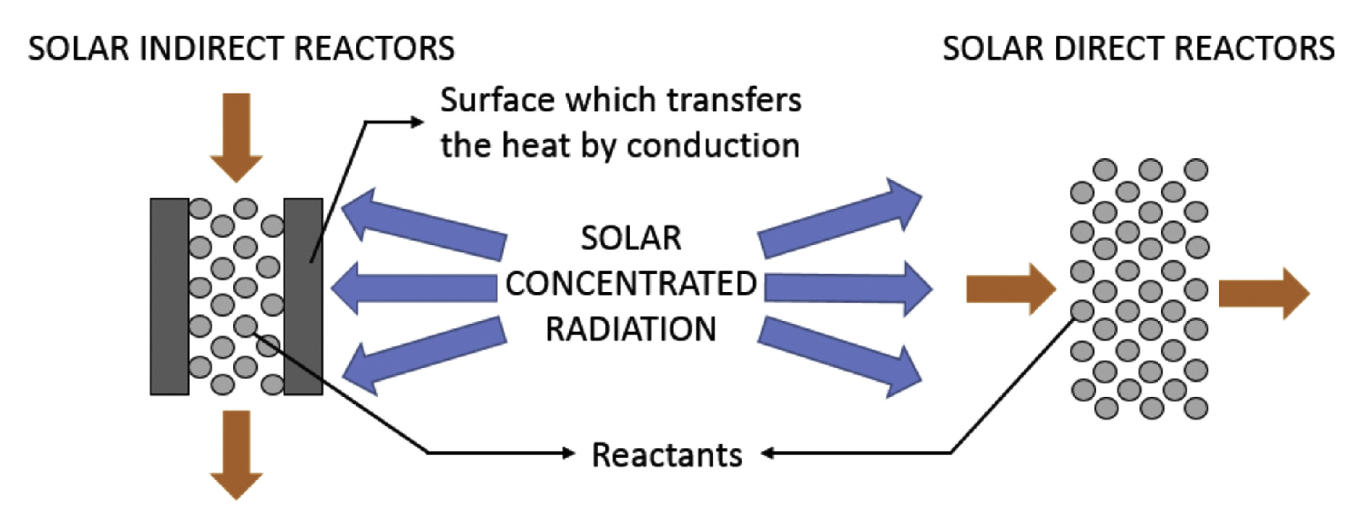
2. Generalities of Solar Receiver/Reactors

In a solar plant, the solar receiver is the unit in which solar energy is absorbed by a fluid and/or solid particles and converted into thermal energy. When the solar energy is used to drive a reaction, the receiver is also a reactor. The most general classification of solar reactors/receivers distinguishes between directly and indirectly irradiated reactors, depending on whether the reactive material receives heat directly by irradiation or by conduction from an irradiated surface [6]. A schematic representation of the difference between directly and indirectly irradiated reactors is presented in Figure 1. Generally, direct irradiation requires the use of a quartz window to prevent the loss of reactive particles or fluid. This solution allows for a more efficient heat transfer compared to an indirectly irradiated reactor and is therefore preferred for reactions that require temperature levels of 1000–1500 °C. On the other hand, the quartz window limits the dimensions of the reactor and is prone to particle deposition and a consequent decrease in the efficiency of the system over time. In the case of indirect heating, the solar radiation may be absorbed by the metal reactor wall, which then transfers the heat to the reactive material or catalyst by conduction. Alternatively, a heat exchanger-type reactor may be envisaged, in which a heating medium receives the solar radiation and transfers it to the reactor wall, which in turn heats the process fluid [5]. The latter solution has been proposed, for example, for the solar-driven steam reforming of fossil fuels in membrane reactors [7,8,9,10]. The presence of a heat transfer fluid represents an additional resistance to heat transport, thereby lowering the maximum operating temperature in the reactor, but also introduces a heat storage medium, thus allowing a continuous operation of the system despite the intermittency of solar radiation. In essence, this solution represents a decoupling between the solar receiver and the reactor and therefore will not be further discussed in the remaining part of this review.
Generally speaking, the main requirements of solar reactors/receivers are:
  • Capacity to reach the required reaction temperatures
  • Material resistance
  • The possibility of scaling up
  • Low energy losses, mainly achieved by reducing re-radiation
  • Low cost
One of the most commonly used parameters to quantify the performance of solar receivers/reactors is the solar-to-chemical energy conversion efficiency, defined as the ratio between the energy stored in the product, Q ˙ c h , and the incident solar radiation on the absorber, Q ˙ s o l a r :
η = Q ˙ c h Q ˙ s o l a r

3. Overview of Proposed Reactor Configurations for Thermochemical Hydrogen Production

In the following paragraphs, a brief overview is provided of the proposed configurations of solar reactors/receivers for different hydrogen production processes.

3.1. Reactor/Receivers for Solar Gasification

Steam or CO2 gasification of carbonaceous materials is a highly endothermic process. The energy for the reaction is traditionally supplied by the combustion of the feed itself with oxygen or air; however, the combustion releases large amounts of CO2 to the atmosphere. The use of high-temperature solar heat to drive the endothermic reactions was first proposed to reduce the overall environmental impact in the 1980s and has attracted interest since [11,12,13,14,15,16,17]. The gasification process may be summarized into two steps: pyrolysis and char (carbon) gasification by either steam or CO2:
Coal or biomass C + CO + CO 2 + H 2 + CH 4 + tar
C + H 2 O CO + H 2
C + CO 2 2 CO
An indirectly heated packed-bed reactor prototype for steam gasification was designed by Piatkowski et al. [18], for application in a beam-down system. A schematic representation is shown in Figure 2. The reactor consisted of two cavities: an upper cavity with a small aperture closed by a transparent window, which served as the absorber, and a lower cavity containing the packed bed. The two chambers were separated by a graphite plate that acted as an emitter. Steam was injected into the lower cavity though a nozzle located at the bottom of the reactor. The reactor walls were realized with SiC tiles, and alumina blocks were used as the insulating material. The reactor was operated to temperatures up to 1200 °C, and the solar-to-chemical conversion efficiency was found to vary between 17 and 29%.
The performance of fixed-bed coal gasifiers is often hindered by ash formation, which limits the extent of the reaction. To avoid this and other drawbacks, the use of fluidized bed reactors was proposed [19]. Gordillo and Belghit [20] modeled a fluidized bed reactor having the same geometric characteristics as those used by Piatkoswski et al. [18], but found that it was less efficient than its fixed-bed counterpart, mainly due to temperature gradients in the reactive volume. The authors suggested moving the heat source to the bottom of the reactor, i.e., where the gas was fed, to improve the temperature homogenization; however, no proposal was made for this alternative reactor design. Directly heated fluidized bed solar reactors were designed and tested by Kodama and co-workers (see, e.g. [21,22]). In the proposed configuration, a draft tube was placed inside the reactor, at the center of the of the fluidized particle bed. The reacting particles were transported upward in the draft tube and downward in the annular region between the tube and the reactor walls in a forced circulation pattern.
Chen et al. [23] designed a cavity receiver fitted with a serpentine tubular reactor for biomass gasification using supercritical water. The reactor was exposed to both the solar irradiation entering through the cavity aperture and the irradiation emitted by the cavity walls. The reactor, designed to operate at temperatures up to 927 K and pressures up to 30 MPa, was divided into two sections. In the first section, water was pre-heated above its critical temperature. The biomass was fed at the entrance of the second section, where the reaction took place. A scheme of the reactor configuration is shown in Figure 3, where the presence of a standby electrical heater is also highlighted.
Melchior et al. [24] extended to biochar steam gasification the use of the reactor previously designed for water-splitting redox cycles [25] and described in greater detail in Section 3.5 of the present review. The authors developed a model to describe the behavior of the 3 kW reactor, validated it against experimental data, and used it to predict the performance of 100 kW and 1 MW scaled-up reactors, designed by inserting multiple absorber tubes within the same cavity receiver. They found that the solar-to-chemical conversion of the two configurations was 39 and 50%, respectively.

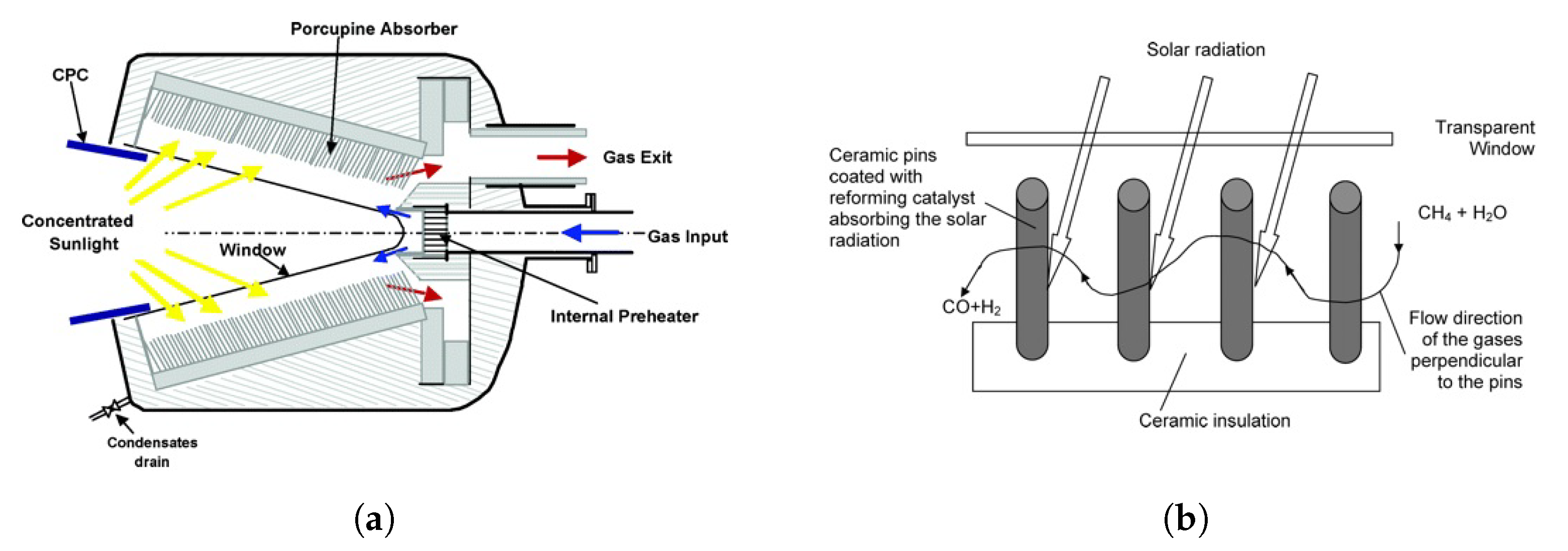
3.2. Reactor/Receivers for Solar Reforming

Similar to gasification, coupling the reforming of fossil fuels to solar heating reduces the overall impact of the process by avoiding the production of CO2 from the combustion reaction necessary to provide heat to the main process. Reviews of the process of solar reforming may be found in [26,27]. The main reactions that take place in these systems depend on the composition of the feed. In the case of methane, the reactions are:
CH 4 + H 2 O CO + 3 H 2
CH 4 + 2 H 2 O CO 2 + 4 H 2
CH 4 + CO 2 2 CO + 2 H 2
H 2 O + CO CO 2 + H 2
Solar reforming reactors may make use of a heat transfer medium, such as molten salts, which due to their high heat capacity, can deliver an almost constant-rate heat supply to the reactor. For instance, Kodama and co-workers [28,29] utilized a molten salt bath, in which they placed the catalyst for the dry reforming of methane. The preheated CH4/CO2 reactant gases were introduced through an aperture at the bottom of the reactor passing through the molten salt containing the catalyst powder.
Direct heating of the catalyst is also possible. For example, a volumetric reactor/receiver for solar reforming of methane was developed at the Weizmann Institute of Science, in which the catalyst was deposited on ceramic pins, referred to as a “porcupine absorber”, irradiated through a transparent window [30,31,32]. The proposed configuration, along with the development of an adequate catalyst, allowed reaching operating temperatures of 1000–1100 °C and pressures up to 20 bar. In addition, the porcupine absorber presented the advantages of allowing radiation to reach a large surface area, and its flexible structure prevented the development of thermal stresses, even in the presence of steep temperature gradients and transient temperature fields. Representations of the volumetric receiver and absorber structure are reproduced in Figure 4a,b, respectively.

3.3. Reactors/Receivers for Solar Cracking

Solar cracking of methane:
CH 4 C + 2 H 2
and other light hydrocarbons has been investigated considerably in the past years [33,34,35,36,37,38,39,40,41,42]. Methane cracking takes place through an initiation reaction:
CH 4 CH 3 * + H *
and the formation of the final products through a free radial chain mechanism:
2 CH 3 * + 2 H * C 2 H 6 + H 2 C 2 H 4 + 3 H 2 2 C + 4 H 4
One of the main difficulties of this process is that the initiation reaction has a high activation energy and is rate-limiting [43,44]. Operating temperatures around 1500 °C are therefore necessary to obtain high conversions. Bertocchi [45,46] investigated the possibility of using a volumetric receiver/reactor in which a cloud of micron- or submicron-sized carbon particle was used as the radiation absorbing medium. These particles may be either injected along with the methane feed at the top of the reactor, as shown in Figure 5, or produced by the cracking reaction itself. In this configuration, solar radiation enters the receiver through a quartz window and is directly absorbed by the carbon particles, which therefore reach a higher temperature than the reactor walls, thereby allowing the use of existing ceramic materials to realize the reactor. More specifically, zirconia was used to for the reactor wall (see Figure 5). A conceptually similar configuration was employed for methane cracking by Yeheskel and Epstein [40] and will be discussed in more detail in Section 5.5.

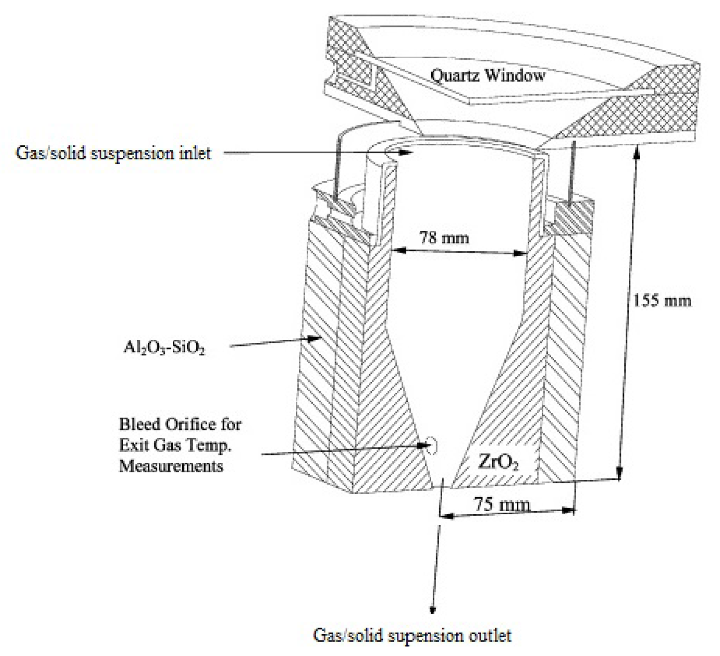
3.4. Reactor/Receivers for Direct Solar Thermolysis

Thermolysis is the most direct method for obtaining hydrogen from water and has attracted interest since the 1970s [47,48,49,50]. In the process, solar irradiation is concentrated onto a reactor in which steam flows to bring it to a temperature at which its dissociation is possible. Despite the apparent simplicity of thermolysis, the reaction presents several important complexities. First and foremost, at atmospheric pressure and temperatures of approximately 2500 K, the degree of dissociation of water is only around 4%. The search and utilization of materials capable of operating at these temperatures and of sustaining the stresses linked to the thermal cycling is the first major challenge. In addition, hydrogen and oxygen are produced simultaneously and must be separated. If the separation is carried out at the extremely high temperatures used in the reaction, the issue of material resistance is extended to the processing units following the reactor. On the other hand, since the degree of dissociation is low and decreases with decreasing temperature, cooling the product mixture will cause a recombination of hydrogen and oxygen. Even if this recombination were avoided, an explosive mixture would form. It is therefore necessary to quench the reactive mixtures through processes that can guarantee cooling rates of the order of 105 K/s. The issue of product separation plays an important role in the design of the reactor [51,52,53,54,55,56,57,58,59]. The following list of possible separating techniques was reported and discussed by Baykara [60]
  • Quenching of product followed by low-temperature separation
    (a)
    Quenching by auxiliary jets
    (b)
    Injection of hot product gas into water
    (c)
    Reaction near an immersed target and cooling of the gas by the surrounding body of water
    (d)
    Dissociation of a jet of steam at low temperature on a hot target and cooling of the product gas coming in contact with the jet
  • High-temperature separation
    (a)
    Separation of H2 using a microporous membrane
    (b)
    Separation of O2 using an electrodiffusion membrane
    (c)
    Separation of H2 using a non-porous metallic membrane
    (d)
    Separation by creation of a high-speed jet
    (e)
    Separation by centrifugation
In [60], the author summarized the results previously obtained by different groups in the operation of solar furnaces for the direct thermolysis of water and presented new results on the operation of a 1 kW solar furnace. A cylindrical solar cavity receiver, shown schematically in Figure 6, was utilized. Porous insulating material surrounded the reactor. The cavity and insulation (labeled (4) in Figure 6) were installed in a support having a Pyrex window (labeled (1)). Depending on the operating temperature, the cavity was realized either with zirconia or alumina. The aperture of the cavity was aligned with the focal point of the concentrating system. Liquid water was fed to the reactor wall (labeled (3)) and evaporated before entering the cavity. Quenching steam was introduced near the front part of the cavity using four perpendicular jets (labeled (2)). The experiment was carried out at temperatures of 2500 and 1500 K. The molar fractions of hydrogen in the outlet gas were 0.03 and 0.0012, respectively, and the efficiency was 1% or lower, in line with the results reported by other groups [56,61]. The low process efficiency along with the technical difficulties related to the high operating temperature explain the drive toward different water-splitting cycles witnessed from the 1990s.

3.5. Reactor/Receivers for Water-Splitting Redox Cycles

Water-splitting redox cycles consist of multiple reactions that take place at different temperatures, all of which are lower than the temperature that would be required for the direct splitting of water and that ultimately result in the production of hydrogen and oxygen from water. As described in [62], water-splitting thermochemical cycles (WSTCs) may be divided into:
  • two-step WSTCs, in which two reactions, one endothermic and the other exothermic, are required to achieve the production of H2 and O2. These processes have the advantage of producing hydrogen and oxygen in two distinct steps, thereby avoiding the requirement of a high temperature gas separation. They may be further divided into redox cycles and hybrid Westinghouse cycles.
    -
    Redox cycles that make use of metal oxides are currently the most widely studied two-step WSTCs. In this case, the first reaction is the endothermic step of the process and consists of the reduction of the oxide, with consequent release of O2. This reaction is also known as the activation step. The second reaction is the exothermic step, during which the reduced oxide is newly oxidized, forming H2 and regenerating the original oxide. Materials that have been considered for application in the thermochemical production of hydrogen include Fe [63,64,65,66,67,68,69], Ce [70,71,72,73], Zn [74,75,76,77,78,79,80,81,82,83,84,85,86], Ti [87], Mn [65,68,88], Co [68], and Sn [83,84,89,90] oxides, as well as ferrites [91,92,93]. These cycles generally operate between the lower temperature of the oxidation step and the higher temperature of the reduction step. More recently, the isothermal splitting of water has been proposed to avoid the irreversible heat and time losses related to the cyclic rotation between the low and high temperatures of the two-step cycles. The process is made possible by (partial) pressure swings between the reduction and oxidation processes. This concept is at the basis of the mixed sodium manganese ferrite cycle, first proposed by Tamaura and co-workers [94] and extensively studied by Varsano and co-workers [95,96,97]. Analyses of water splitting cycles based on gas composition pressure swings have been presented in [98,99,100], and thorough discussions of such cycles isothermally were reported in [101,102].
    -
    The first hybrid Westinghouse cycle to have been proposed was the sulfur cycle, in which sulfurous acid and water react electrolytically, producing hydrogen and sulfuric acid. The latter is vaporized to produce steam and sulfur trioxide, which is then reduced at higher temperatures into sulfur dioxide and oxygen. The final mixture is separated, and sulfur dioxide is recycled to the electrolyzer [103].
  • Multi-step WSTCs consist of more than two reaction step. Their drawbacks are mainly related to the potentially lower efficiency of the process, but lower operating temperatures may be achieved compared to those usually required by two-step processes. In addition to the older three-step sulfur-iodine cycle [104], Mn-oxide based three-step cycles have been more recently proposed [62,105,106]. The use of nanoparticles was also found to have a beneficial effect on lowering the maximum temperature of the cycle [107].
Water-splitting reactors/receivers may be broadly classified as monolithic reactors or particle reactors [108]. In monolithic reactors, the reactive material is static, be it self-supporting or supported on a scaffolding, and the reduction and oxidation steps are controlled by changing the temperature or chemical environment. Monolithic reactors can be further classified as static or rotating. The simplest configuration is that of cavity reactors and stationary monolithic reactors. For cycles requiring temperature swings, the reactive material is exposed to concentrated sunlight during reduction, while the irradiation is reduced during the oxidation step by directing the solar beam away from the reactive chamber. In particle reactors, the reactive solid flows between the reduction and oxidation zones. The decoupling between the two reactions thus achieved is advantageous as the reduction and oxidation steps are generally characterized by different reaction rates. On the other hand, the challenge of high temperature solid flows must be met.
Agrafiotis et al. [109] proposed the use of a cavity reactor with a flat absorber surface for water-splitting cycles using as redox materials MnZn- and NiZn-doped ferrites supported on a ceramic honeycomb. An indirectly heated cavity reactor was instead proposed by Varsano and co-workers [96,110], in which the reactive material was placed inside the cavity in the form of spherical pellets and heated indirectly through the reactor walls, thus avoiding the need for a quartz window. A preliminary thermal characterization was carried out on an AISI 316 reactor filled with inert material [110], and an Inconel reactor was then used for the actual water-splitting process [96]. The configuration proved to be suitable for the reaction temperatures required by the redox reaction on a manganese ferrite-sodium carbonate mixture. In theory, this configuration can be scaled up, because of the absence of a quartz window; however, an excessive increase in the reactor size could affect the heat transfer efficiency, thus resulting in cold spots that would not allow the redox reaction to take place as required.
Another design that did not make use of a quartz window was the one proposed in [25]. The solar cavity-receiver consisted of a cylinder made of YO2-stabilized ZrO2, lined with Al2O3 insulation. The tubular absorber was concentric with the cavity, which had a rectangular aperture on the top to let in the solar irradiation. A compound parabolic concentrator was incorporated into the cavity’s aperture. A schematic representation of the receiver and concentrator is shown in Figure 7, where the concentric cavity and absorber are shown in gray and the rectangular aperture is shown to have width w.
The scale-up of this system is the SurroundSun reactor [111,112,113], in which the reactive material is packed in multiple reaction tubes, housed within an insulated cavity. This reactor may be operated in both the temperature swing mode and isothermal mode. The distinction between the two operating modes is made possible by acting on the direction of the solar input. In the first case, the solar radiation is directed so that only half the tubes are exposed to solar radiation, and the reactive material contained in them undergoes reduction, while the other half of the tubes are fed with steam and undergo oxidation. After some time, the direction of the solar radiation is switched so that the tubes that had previously been working in the oxidation state are heated and can operate the reduction. In the second case, all tubes are exposed to the solar radiation, and the reaction taking place in each tube is determined by the composition of the gas feed. The reaction configuration is shown in Figure 8, from which it can be seen that in both cases, half of the tubes are fed with steam, while the other half is fed with inert gas. The figure highlights that the difference between the temperature swing and isothermal operation mode lies in the orientation of solar radiation, which may be toward either some or all of the tubes.

4. Generalities on Solar Receiver/Reactor Modeling

All models of solar receivers/reactors, developed to describe the performance of the system, include the following phenomena:
  • Heating of the reactive material
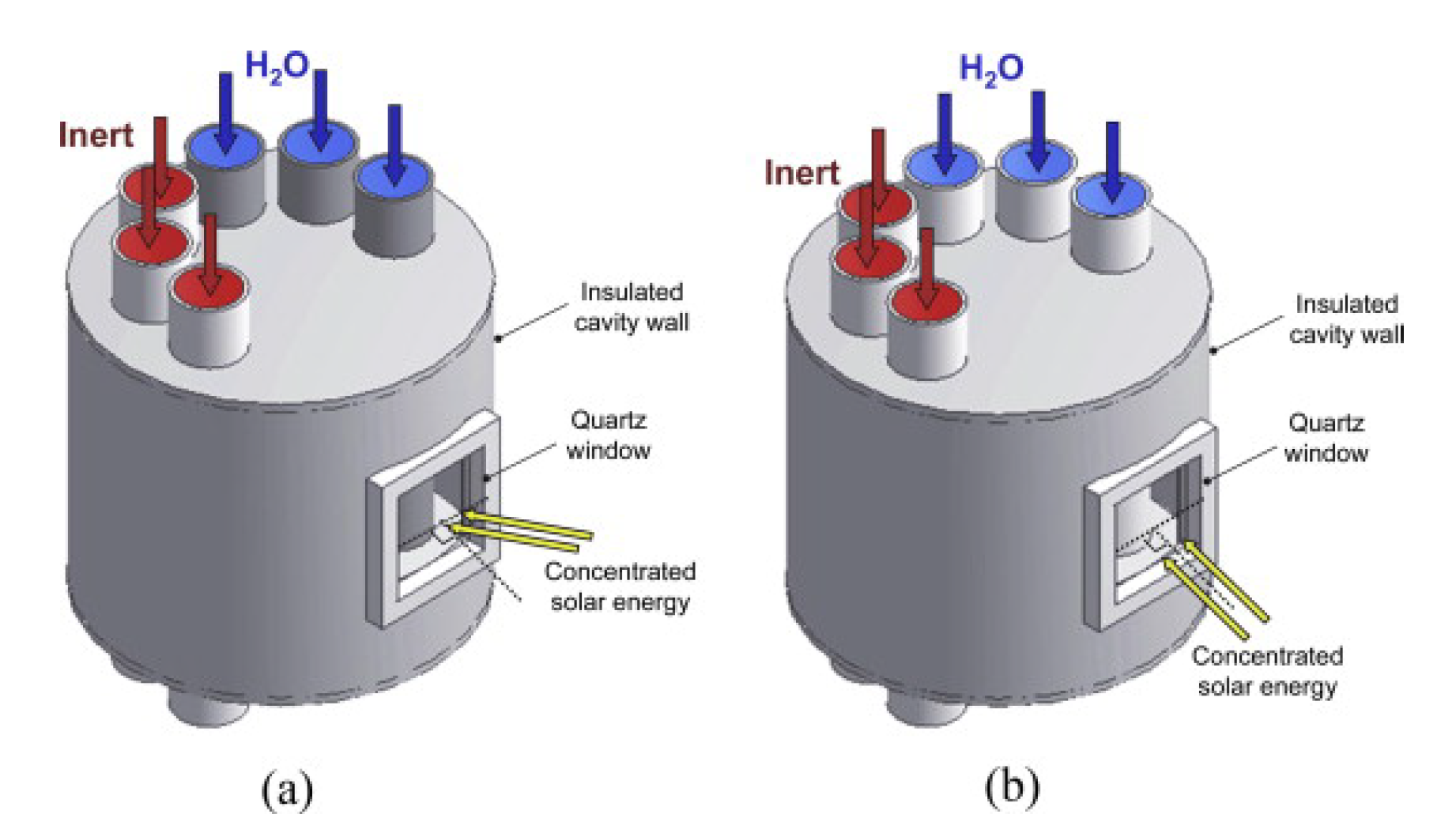
    • To describe the heating received by the reactive material, it is necessary to study the irradiation distribution. As described in detail by Lanchi et al. [110], the absorbed radiation is a purely optical quantity. It is generally evaluated through a Monte Carlo ray-tracing technique. Its distribution depends on the geometric characteristics of the concentrating facility and of the receiver, as well as the characteristics of the absorber material (absorbance and reflectivity). These, in turn, depend not only on the nature of the material itself, but also on its state of oxidation and potential deposition of particles. For indirectly heated reactors, heat conduction from the irradiated surface to the reactive material must also be described. For directly radiated reactors, the effect of possible fouling of the cavity window should be accounted for.
  • Heat losses to the environment through convection
    • Naturally, some heat losses take place toward the environment, which is at a lower temperature level compared to the receiver surface. Heat losses through the outer walls of receivers are generally neglected as these are insulated. On the other hand, particularly in the case of indirectly irradiated cavities, the inner wall is exposed to still air, and heat loss through natural convection must be accounted for.
  • Heat losses to the environment through thermal re-radiation
    • The receiver emits radiation towards the environment. The heat loss due to thermal re-emission may be evaluated as [110]:
      q _ e m i s = f ε σ T 4 _ w T _
      where f is a factor quantifying the fraction of radiation that is emitted from the cavity toward the environment, σ is the Boltzmann constant, ε is the wall emissivity, T w is the wall temperature, and T is the sky effective radiative temperature and is approximately equal to the ambient temperature.
  • Fluidodynamics
    • As mentioned above, the type of reaction and the operating conditions determine whether solar receivers/reactors should be designed as fixed bed reactors, fluidized bed reactors, or particle reactors. Depending on the chosen configuration, the flow conditions may have a significant effect on the overall behavior of the system.
  • Reaction rate
    • The rate of reaction is often studied separately, and the rate expression developed is employed in the model of the solar receiver/reactor.
In the case of significant temperature swings during reactor operation and depending on the material characteristics, it may also become important to describe thermal stresses generated in the reactor and analyze the possibility of material failure.

5. Selected Examples

In this section, selected examples of methodologies followed to design solar receivers/reactors and relative results are presented and discussed. As mentioned in the Introduction, the aim of this section is to gain more insight into the procedures followed to tailor the reactor design to the specific needs, rather than on the final configuration itself.
In all the cases reported here, the procedure can be roughly summarized as follows:
  • Select a general configuration
  • Identify the criterion based on which the “optimal” reactor characteristics can be defined
  • Develop a model to describe the behavior of the reactor
  • Analyze the results of the models and the effect of changes in the geometry
  • Select the “optimal” configuration
Each group analyzed the solar reactor/receiver configurations and identified the “optimal” solution based on one or more of these criteria:
  • Maximize energy conversion efficiency
  • Minimize losses associated with process irreversibilities, i.e., exergy analysis
  • Minimize thermo-mechanical stress

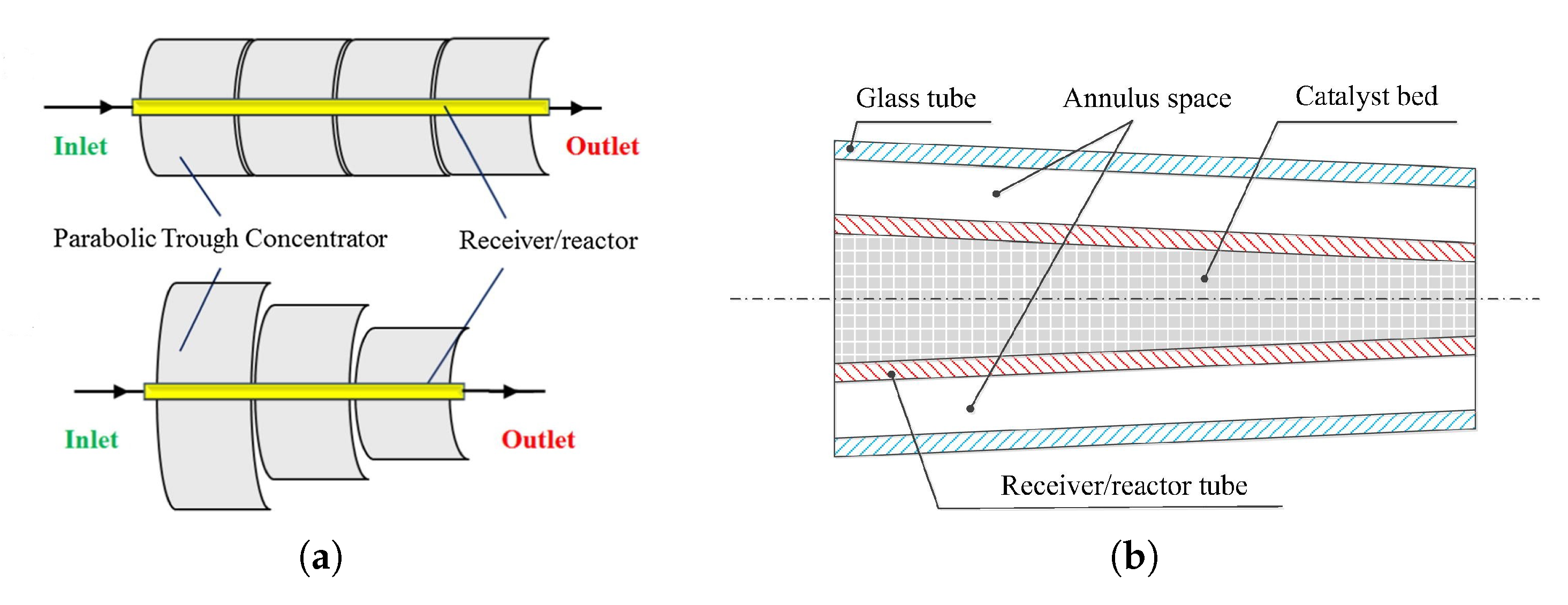
5.1. Tubular Reactor/Receiver for Steam Reforming [114]

Wang et al. [114] studied a solar reactor/receiver for the steam reforming of methanol and carried out an improvement of the reactor design based on an increase in the solar-to-fuel conversion efficiency (Equation (1)). Here, Q ˙ c h is chemical energy derived from the conversion of methanol and is defined as the number of moles of converted hydrogen times the heat of reaction:
Q ˙ c h = X C H 3 O H n ˙ C H 3 O H Δ H r
and Q ˙ s o l a r is the solar heat flux, defined as:
Q ˙ s o l a r = I A η c
where I is the incident solar radiation, A is the area exposed to the radiation, and η c is the efficiency of the solar concentrator.
In the system considered (see Figure 9), the reaction takes place within a high-transmittance tube containing the catalyst and placed along the focal line of the parabolic concentrator. The authors modeled the performance of the system through a 3D model accounting for momentum, mass, and heat transport. With regards to heat transport, in addition to heat transfer by radiation, both convection and conduction were considered in all three directions, and the heat of reaction was included as source term. The model developed for the traditional setup, shown in the top part of Figure 9a, was previously validated against experimental results [115]. A non-uniform distribution of the reaction rate was observed, which was caused by a mismatch between the solar heat flux and the distribution of reactants within the tube. More specifically, the reaction rate was low toward the inlet of the tube, where the temperature was low, and toward the outlet of the tube, where the reactant concentration was low. To overcome this situation and guarantee a better use of the collected solar energy, the authors proposed to adjust the aperture width of the concentrator along its length, in order to increase the heat flux toward the inlet of the reactor and decrease it toward the outlet. By using a linearly decreasing concentrator width, the methanol conversion could be increased while lowering the maximum catalyst temperature and reducing the required reactor length from 8 to approximately 6 m. This adjustment is illustrated in the bottom scheme of Figure 9a. The tube diameter was then varied to improve the match between the rate of methanol conversion and collected solar energy without changing the reactor volume. While the initial configuration was that of a tube with a constant inner diameter of 65 mm, the modified configuration presented a diameter that decreased linearly along the tube length from 85 mm to 55 mm (shown in Figure 9b).
The better performance of the new configuration was quantified in terms of the higher solar-to-fuel conversion efficiency (Equation (1)) and methanol conversion, which were verified under different conditions of incident solar radiation and steam to methanol ratio. The authors obtained almost complete methanol conversions and solar-to-chemical energy efficiencies around 90%.

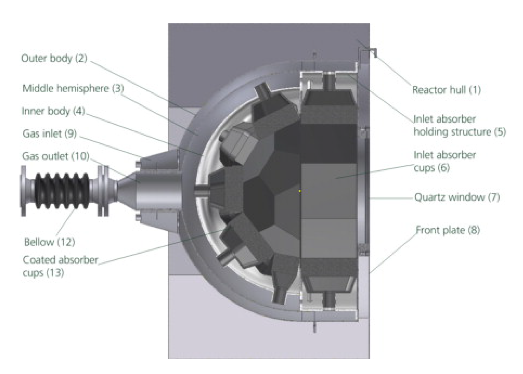
5.2. Directly Heated Receiver/Reactor for Thermochemical Water-Splitting [4]

Houaijia et al. [4] based the design of the solar reactor/receiver for thermochemical water-splitting redox cycles on an exergy analysis, i.e., the evaluation and minimization of thermodynamic losses due to irreversibilities. The authors started with an exergy analysis of the entire process, including not only the solar reactor, but also the heat exchangers, evaporators, PSAunit, and hydrogen compression. For each unit, two main quantities were evaluated, namely the exergy efficiency, ε k , defined as the ratio between the exergy streams of the product of and fuel to the k th unit, E ˙ P , k and E ˙ F , k , respectively:
ε k = E ˙ P , k E ˙ F , k
and the exergy destruction ratio, y D , k , defined as the ratio between the exergy destruction in the k th unit and the overall fuel supply, E ˙ F , t o t :
y D , k = E ˙ D , k E ˙ F , t o t
The exergy destruction was defined as:
E ˙ D , k = E ˙ F , k E ˙ P , k E ˙ L , k
where E ˙ L , k is the exergy loss in the k th component, usually equal to zero if its boundaries are at the minimum temperature level involved in the process. The results of the exergy analysis revealed that about 60% of the losses took place in the solar reactor. Improving its design could therefore lead to a significant improvement in the energetic performance of the process. The first step in the design of the reactor consisted of identifying the main source of losses in the reactor, which was found to be thermal radiation from the hot absorber front to the environment. This loss depended on the temperature and area of the absorber’s surface. Since the lower limit of the former was given by the reaction requirements, the only solution was to reduce radiation losses through a decrease in the absorber’s surface area. It is well known that cavity designs are the most appropriate choice to reduce thermal losses from solar reactors/receivers; however, different cavity shapes are possible. It should be noted that, in this case, the design procedure was constrained by the need to operate with an overall thermal input of 1 MW and with a directly heated reactor. Directly heated reactors are sealed with quartz windows who’s radius, as also stated by the authors, cannot exceed 0.5 m to avoid its cracking following thermal stresses. This puts a limit on the size of the reactor. In turn, the need to obtain a thermal input of 1 MW means that a modular reactor design is necessary, and therefore, secondary concentrators are needed to avoid spillage of radiation between individual cavities. The choice of absorber shapes is therefore narrowed down to those that can be exposed to radiation from a secondary concentrator. In their work, Houaijia et al. considered the possibility of employing either a flat, conical, or spherical absorber. For all three shapes, a parametric study was carried out varying the distance between the absorber and the secondary concentrator outlet. For the conical and spherical shapes, an additional parameter was taken into consideration: the opening angle for the cone and the curvature of the cap for the cone. The comparison between the performance of the different reactor configurations was carried out based on the value of a quality parameter Q defined as:
Q = I C 60 A a b s , 60
where I C 60 and A a b s , 60 are defined as follows:
  • I C is the intercepted power on the absorber surface, defined as the ratio between the power absorbed and the power entering the secondary concentrator.
  • A a b s is the dimensionless surface area of the absorber normalized with respect to the inlet aperture area of the secondary concentrator. This parameter is important because the absorber surface area is proportional to the reactive area. A higher value of A a b s is therefore equivalent to a higher amount of reactive material.
  • The subscript 60 refers to the fact that for the irradiation to be useful for the reaction, it cannot exceed a maximum value, Q m a x , to avoid overheating and consequent damage of the reactive material, and it cannot decrease below a minimum value, to avoid an excessive drop in reaction rate. For this reason, the radiative flux was considered to be useful if included between Q m a x and 60% of Q m a x
It is interesting to note that the authors pointed out that the lower limit for useful radiation, i.e., 60% of Q m a x , was quite arbitrary, but the results in terms of reactor design did not change significantly if the limit was placed to 70% or 80% of Q m a x , whereas noticeable differences emerged if no limitation was placed on the value of the heat flux. The result of their analysis indicated that the most efficient absorber was spherical, with a curvature of one, i.e., a complete hemisphere, and a distance from the outlet of the secondary concentrator of 0.4 times the inlet diameter of the concentrator. This was achieved by introducing an aluminum oxide spacer. A representation of the designed hemispherical absorber is shown in Figure 10. The fluid flows through the inlet ring (9), which surrounds the outlet pipe and is then led between the outer body (2) and the middle hemisphere (3) towards the inlet absorber (5 and 6). This flow pattern allows the inlet fluid to act as a heat shield between the hot inner part of the reactor and the cooler outer part. In addition, a first heat exchange takes place between the incoming and outgoing fluids. The feed then enters the chamber between the quartz window (7) and the coated absorber cups (13), where the reaction takes place. The gases leaving the honeycomb flow between the inner body (4) and the middle hemisphere (3). Subsequently, the gas leaves the reactor at the outlet (10) to the periphery.

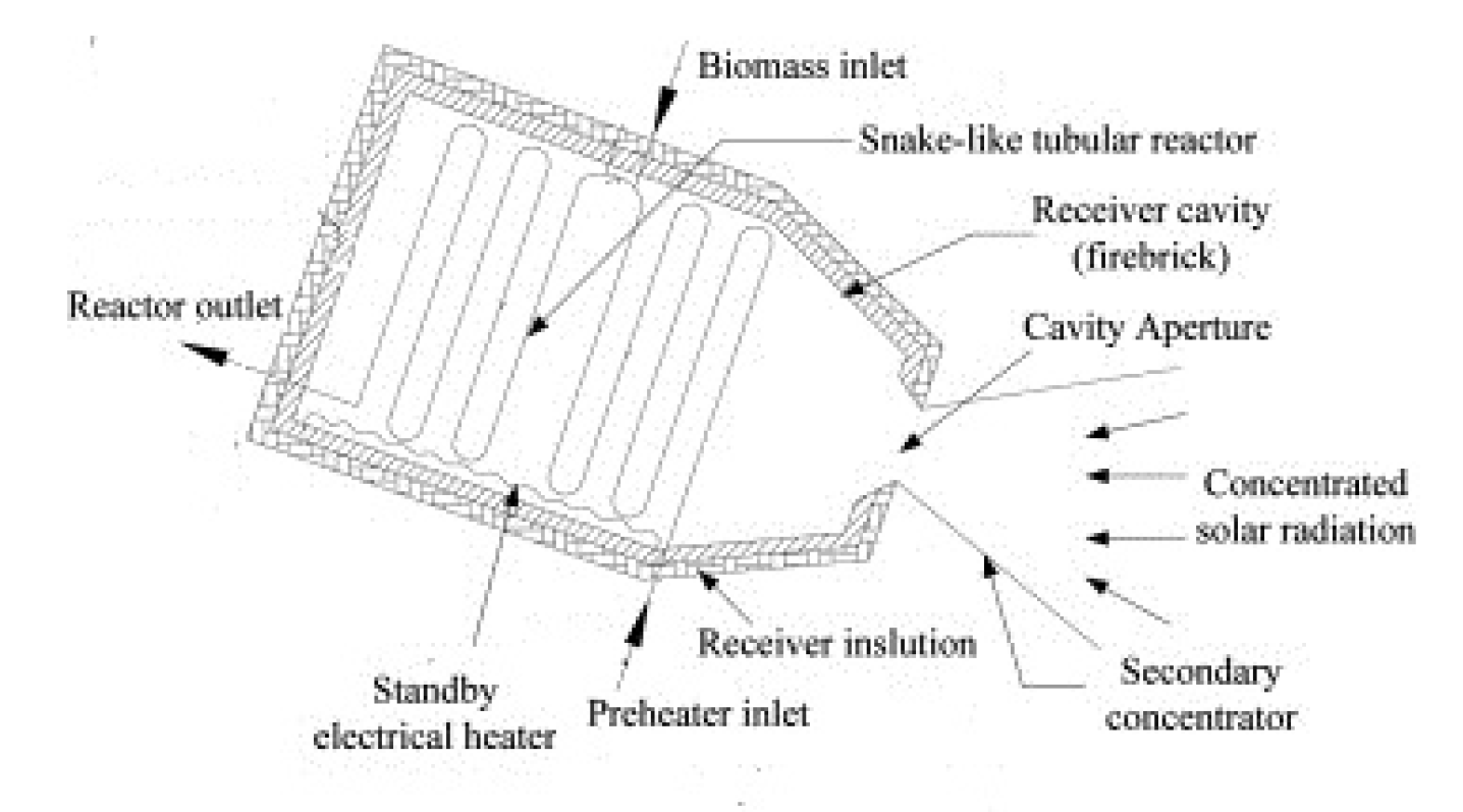
5.3. Receiver/Reactor for the Gasification of Solid Particles [116]

Z’Graggen and Steinfeld [116] worked on the optimization of reactor geometry and operating parameters for the solar steam gasification of carbonaceous particles. The feed considered was that of petroleum coke (petcoke), which had a variable composition that could be generally expressed as CH z O y . The starting reactor geometry was designed, tested, and modeled in previous works by the same group [117,118] and consisted of a cylindrical cavity-receiver with a circular aperture closed by a transparent quartz window to let in the concentrated solar radiation (see Figure 11). The cavity was designed to optimize the capture of incident solar radiation and allowed considering the absorber as a black body. A slurry of water and coke particles was injected at the front of the cavity through tangential injection nozzles and formed a vortex-like flow that followed a helical path toward the rear of the cavity, indicated with a dashed line in Figure 11. The coke particles were therefore directly exposed to the solar radiation, thereby improving the heat transfer efficiency. The energy absorbed by the reactants was used to generate and superheat the steam, heat the solid reactant’s temperature above 1300 K, and drive the gasification reaction.
A two-phase reactor model accounting for radiative, convective, and conductive heat transfer, as well as the reaction kinetics and accompanying heat effects was employed. Steady-state conditions were considered. The reaction modeled was:
CH z O y + ( 1 y ) H 2 O z 2 + 1 y H 2 + CO
where the values of z and y depend on the composition of the feed. The overall mass balance equation was expressed as:
· ρ · u = 0
and for the single i th species:
· ρ Y i · u = R i
where R i is the rate of production of the i th component. The energy transport equation for both phases reads:
· ρ h · u = ϕ r a d i a t i o n ϕ r e a c t i o n
where ϕ r a d i a t i o n and ϕ r e a c t i o n are the terms of heat generation due to the incoming solar radiation and endothermic reaction, respectively, and are defined as:
ϕ r a d i a t i o n = 4 π λ = 0 κ λ ( S ) 1 4 π ω 0 4 π i λ ( S , ω ) d ω i λ b ( S ) d λ
and
ϕ r e a c t i o n = i = 1 n h i ( T ) · R i T , Y i , f
where κ is the absorption coefficient, λ is the spectral wavelength, and i is the radiation intensity.
The authors investigated the effect of varying four parameters:
  • particle size
  • feeding rate
  • input power
  • geometry of the cavity’s longitudinal section (radius and length) at constant reactor volume
The reactor’s performance was characterized by three indicators, namely:
  • Extent of feed conversion, X C
  • Solar-to-chemical energy conversion efficiency (Equation (1))
  • upgrade factor, defined as the ratio between the calorific content of the gaseous products and that of the solid feed:
    F U = m ˙ H 2 · L H V H 2 + m ˙ C O · L H V C O m ˙ c o k e , i n · L H V c o k e
The authors carried out their analysis both for the 5 kW reactor that had been experimentally tested in other works, and for which experimental results were available to validate the data, and for the 300 kW scale-up reactor. Complete reaction was found for feed particles having initial diameters in the range of 2–7 and 11–35 μm, at residence times of 1.4 and 9.7 s, and maximum temperatures of 2046 and 1818 K for the 5 and 300 kW reactors, respectively. An investigation of reactant conversion as a function of particle diameter and reactor configuration revealed that for the 5 kW reactor, two local maxima existed. The first maximum was achieved for a set of particle radius/reactor configuration conditions that reduced the conductive heat losses to the minimum value obtained under the range of conditions studied. The second maximum was instead achieved under conditions that maximized the exposure of the particles to the direct solar radiation. For the 300 kW reactor, only one maximum point was found. This was attributed to the fact that the latter configuration required the use of a thicker insulation layer, thus reducing the effect of conduction losses. These conclusions highlighted the fact that the performance of the system depended on a number of factors and that it was difficult to optimize all such factors at the same time. On the other hand, a correct design of the reactor and operating conditions can allow an improvement in the efficiency of solar energy conversion.

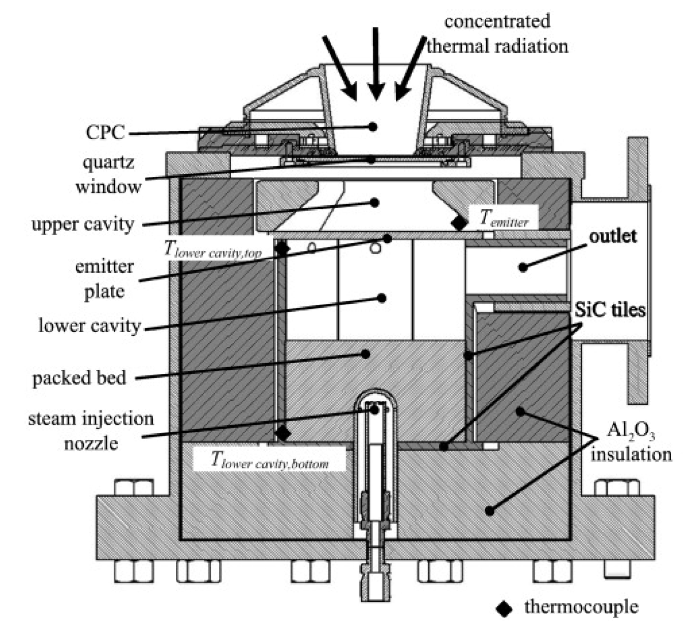
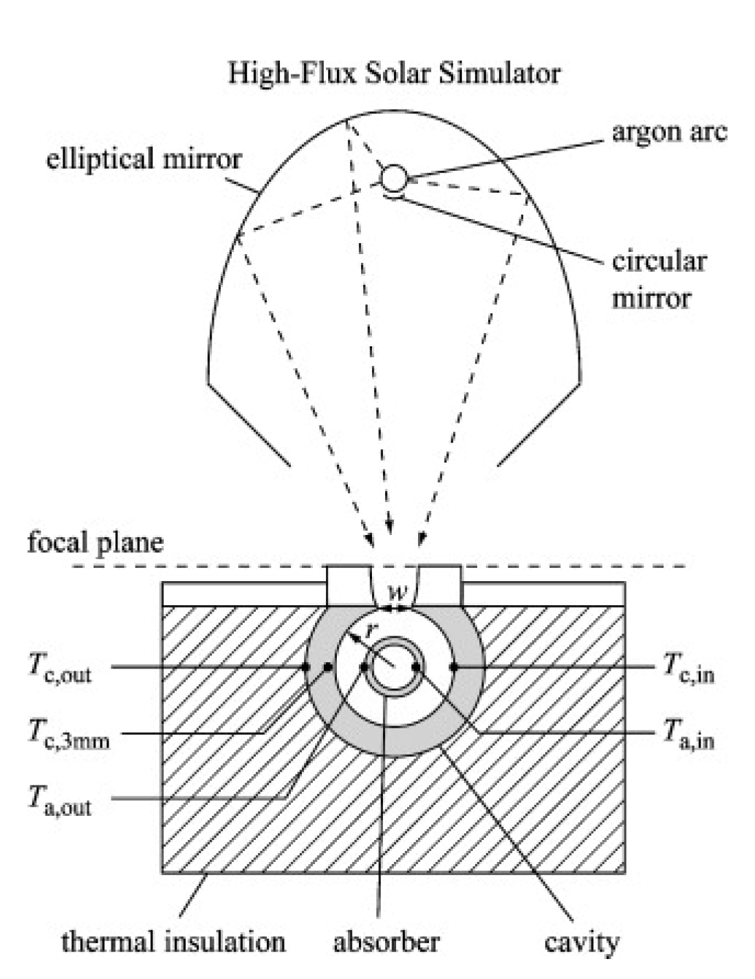
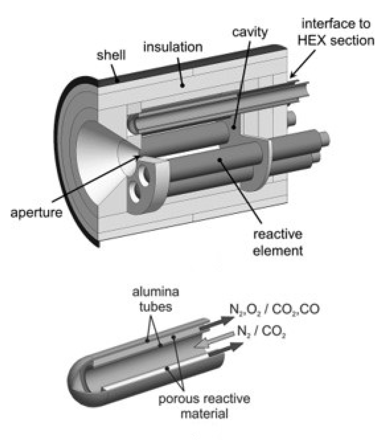
5.4. Indirectly Heated Receiver/Reactor for an Isothermal Redox Cycle [119]

Bader et al [119] presented the design procedure for a solar thermochemical CO2 splitting by isothermal redox cycling of ceria. The redox reactions are:
CeO 2 CeO 2 δ + 1 2 δ O 2
CeO 2 δ + δ CO 2 CeO 2 + δ CO
Although the present review focuses on hydrogen-producing reactions, this work was selected because the cycle described here may also be used for the splitting of water; in this case, the reactant of the oxidation reaction (27) would be water instead of carbon dioxide, and the product would be hydrogen, rather than carbon monoxide.
The reactor, shown in Figure 12, consists of a cylindrical cavity containing an array of reactive elements, arranged along the cavity walls. Each reactive element is made of two concentric alumina tubes. A packed bed of porous ceria particles is contained in the annular region between the two tubes. Details of the reactive element are shown in the bottom panel of Figure 12. The cycle is conducted by alternating the gas flow through the reactive elements between nitrogen sweep gas, to reduce the ceria, and CO2. The gas enters the element through the inner reactor tube and changes direction at the domed end of the outer tube. The gas entering the annular volume containing the ceria particles is therefore preheated. Concentrated solar radiation enters the cavity through the aperture.
The authors discussed a basis for the choice of the characteristics of the packing and design parameters of the reactor. The results may be summarized as follows:
  • With regards to the material morphology, porous particles were chosen over solid particles, a porous ceria monolith, and a reticulate porous ceramic (RPC), due to the good combination of large surface area per unit of mass, favorable for the reaction kinetics, rapid heat transfer, and low pressure drops.
  • Specific gas flow rates and duration of each cycle step were selected to maximize CO production on the basis of results obtained on 1 g of porous ceria particles tested in an infrared imaging furnace. The validity of scaling these results to a larger reactor was confirmed in previous works by some of the same authors [120,121].
  • Based on the optimization described in the previous step, the mass of porous ceria particles required for the 3 kW prototype was established.
  • The length-to-radius ratio of the cavity was selected to be equal to two, to obtain an apparent absorptivity close to unity.
  • The diameter of the cavity aperture was selected to accommodate a solar power input of 3 kW at an average flux of 3 MW/m2.
  • Tube radii were selected from standard tube sizes based on considerations relative to the ease of operation, but also from an estimation of the mechanical stresses.
Concerning the last point, thermal and thermo-mechanical models were developed to evaluate the steady-state profiles of temperature and static stress and evaluate the static factor of safety. A value of the static factor of safety lower than one indicates that static failure of the material is expected. The authors pointed out that their evaluation did not include the start-up and shut-down phases and relative cyclic stresses. In addition, some discrepancy is expected between the model and the actual behavior of the system. For these reasons, a static factor of safety significantly higher than unity is to be obtained in order to consider the operation of the system to be safe.

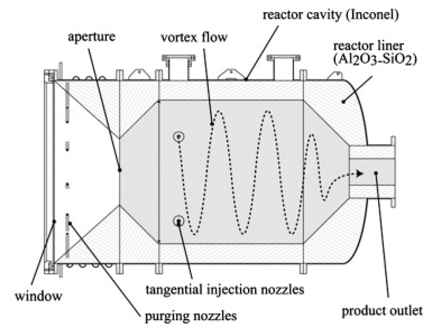
5.5. Directly Heated Particle Receiver/Reactor [122]

An interesting approach to the design of directly irradiated solar receivers/reactors to be employed when either a reactant or product is in a powder form was the one proposed by Kogan and Kogan [122]. The starting point was the observation that for these cases, specific care must be taken to prevent contact of the incandescent powder particles with the quartz window, which could bring the formation of hot spots on the surface of the window and its consequent destruction by localized overheating. An auxiliary gas flow can be employed to screen the window from the powder; however, auxiliary gas flow rates can be 30-80% of the value of the main gas flow rate, resulting in a significant reduction in the overall reactor efficiency because a substantial part of the heat delivered to the reactor goes to heating the auxiliary gas. The authors studied a reactor configuration that allowed reducing the auxiliary gas flow rate down to 5% of that of the main gas. The design procedure started with a very simple reactor configuration and proceeded with increasing degrees of complexity to improve the fluidodynamics configuration and utilization of solar irradiation. Tests were carried out using a smoke flow visualization technique, in which one of the two gas streams was made visible by charging it with heavy smoke, while the other was left in its naturally transparent condition.
The first reactor configuration tested was simply a cylindrical Pyrex vessel in which an annular partition was utilized to divide the reaction zone from a buffer zone near the top of the vessel. The main and auxiliary gas streams entered the vessel in the reaction and buffer zone, respectively. The auxiliary stream then discharged into the reaction zone through the annular partition. The exit of both gas streams took place from a port at the bottom of the reactor. The main gas stream was fed tangentially to the reaction zone, thus generating a whirling flow. The auxiliary gas was introduced either tangentially or radially. These tests showed that a radial inlet of the auxiliary gas performed better in terms of eliminating the presence of the main gas from the buffer zone. This finding was the basis for the following tests, carried out on a more complex reactor design, shown in Figure 13.
In the reaction configuration shown above, the gas entry tubes were replaced by two narrow annular passages. This modification led to two simultaneous benefits. The first is that the solar radiation from the compound parabolic concentrator (CPC) to the cavity was not obstructed by tubes. The second was that the annular passages allowed the introduction of the two gas streams as continuous thin films. Tests were carried out on the reactor shown above with different combinations of auxiliary and main gas flow rates. Without going into the detail of all the tests reported, it is interesting to note that the first experiment was carried out by introducing only the auxiliary gas, which progressed adjacently to the reactor window for some distance, but then detached from the surface of the window before reaching its center. When the main gas was introduced, the annular area of the window swept by the auxiliary stream was reduced, as the gas was sucked away from the window by the main gas stream. This tornado-like effect was found to be decisive to keep solid particles away from the quartz windows, and the following tests were carried out with the aim of identifying conditions capable of creating a “stable tornado”. The authors were able to enhance the tornado effect with a specific pair of auxiliary and main gas flow rates that allowed efficient window screening even with an auxiliary gas flow rate equal to only 5% of that of the main gas stream. In more general terms, three conditions were found to be required to generate a tornado windscreen: (i) the main gas stream must be introduced tangentially into the reactor cavity; (ii) the products of the reaction should be extracted from the reactor cavity in the axial direction, preferably through a narrow channel placed along the axis of symmetry of the reactor; and (iii) the auxiliary gas stream should be introduced radially into the reactor cavity and close to the window.

6. Conclusions

Solar reactors/receivers may be employed in a wide variety of thermochemical processes for the production of hydrogen. A number of different configurations is possible, and the choice depends on factors such as the physical state of the reactants and products, the operating temperature, and the thermal effects of the reaction. Reviews previously published on the subject of solar receiver/reactor design were generally limited to a description of the proposed configurations. An immediate observation that can be made from these reviews is that the design of solar receivers can vary significantly, even when the operating conditions are apparently similar. The aim of the present work was to highlight the reasons for which a specific design was selected. In this context, an overview of receiver/reactor configurations proposed in the literature and of their fields of application was presented, thus providing insight into the complexity of the problem. Generalities on modeling of such systems were then reported to give an idea of the phenomena that must be taken into account in the description of solar receivers and of the number of design parameters on which it is possible to act to improve their performance. Finally, selected examples were discussed in detail to highlight the different routes that may be followed and provide guidelines for reactor optimization.
In general terms, the first step consisted of identifying the optimization criteria. The parameters on which it was possible to act to improve the reactor design and operation were then identified, and their effect on the performance of the system was studied. An intermediate set of variables could also be selected to analyze the behavior of the reactor. Such variables were closely linked to, but did not coincide with the optimization parameters. Their analysis allowed understanding how the operating parameters bring about the change in performance.
The main optimization parameters were found to be:
  • Energy conversion efficiency
  • Energy losses associated with process irreversibilities
  • Thermo-mechanical stress
The intermediate variables that could be analyzed to gain insight into the behavior of the systems were:
  • Reactant conversion
  • Temperature uniformity within the reactor
  • Ratio between the calorific content of the products and the reactants
The reactor and operating parameters on which it was possible to act were:
  • Receiver shape and dimensions
  • Mode of reactant feed
  • Particle morphology in the case of solid reactants
A correct assessment of the influence of the operating parameters on the behavior of the reactor allowed choosing the most adequate reactor configuration, thereby increasing the overall efficiency of the process.

Funding

This research received no external funding

Conflicts of Interest

The authors declare no conflict of interest

References

  1. Steinfeld, A. Solar thermochemical production of hydrogen-a review. Sol. Energy 2005, 78, 603–615. [Google Scholar] [CrossRef]
  2. Villafan Vidales, H.I.; Arancibia Bulnes, C.A.; Riveros Rosas, D.; Romero Paredes, H.; Estrada, C.A. An overview of the solar thermochemical processes for hydrogen and syngas production: Reactors, and facilities. Renew. Sustain. Energy Rev. 2017, 75, 894–908. [Google Scholar] [CrossRef]
  3. Romero, M.; Steinfeld, A. Concentrating solar thermal power and thermochemical fuels. Energy Environ. Sci. 2012, 5, 9234–9245. [Google Scholar] [CrossRef]
  4. Houaijia, A.; Sattler, C.; Roeb, M.; Lange, M.; Breuer, S.; Säck, J.P. Analysis and improvement of a high-efficiency solar cavity reactor design for a two-step thermochemical cycle for solar hydrogen production from water. Sol. Energy 2013, 97, 26–38. [Google Scholar] [CrossRef]
  5. Kodama, T.; Bellan, S.; Gokon, N.; Cho, H.S. Particle reactors for solar thermochemical processes. Sol. Energy 2017, 156, 113–132. [Google Scholar] [CrossRef]
  6. Tapia, E.; Iranzo, A.; Pino, F.J.; Rosa, F.; Salva, J.A. Methodology for thermal design of solar tubular reactors using CFD technique. Int. J. Hydrog. Energy 2016, 41, 19525–19538. [Google Scholar] [CrossRef]
  7. Giaconia, A.; Monteleone, G.; Morico, B.; Salladini, A.; Shabtai, K.; Sheintuch, M.; Boettge, D.; Adler, J.; Palma, V.; Voutetakis, S.; et al. Multi-fuelled solar steam reforming for pure hydrogen production using solar salts as heat transfer fluid. Energy Procedia 2015, 69, 1750–1758. [Google Scholar] [CrossRef]
  8. Said, S.A.; Simakov, D.S.; Waseeuddin, M.; Roman-Leshkov, Y. Solar molten salt heated membrane reformer for natural gas upgrading and hydrogen generation: A CFD model. Sol. Energy 2016, 124, 163–176. [Google Scholar] [CrossRef]
  9. Murmura, M.A.; Cerbelli, S.; Annesini, M.C. Modelling and optimization of hydrogen yield in membrane steam reforming reactors. Can. J. Chem. Eng. 2017, 95, 1676–1682. [Google Scholar] [CrossRef]
  10. Murmura, M.A.; Cerbelli, S.; Annesini, M.C. Designing the optimal geometry of a membrane reactor for hydrogen production from a pre-reformed gas mixture based on the extent of the reaction boundary layer. Chem. Eng. Process.-Process Intensif. 2017, 120, 148–160. [Google Scholar] [CrossRef]
  11. Aiman, W.R.; Thorsness, C.B.; Gregg, D.W. Solar coal gasification: Plant design and economics. AIChE J. 1981, 77, 36–46. [Google Scholar]
  12. Beattie, W.H.; Berjoan, R.; Coutures, J.P. High-temperature solar pyrolysis of coal. Sol. Energy 1983, 31, 137–143. [Google Scholar] [CrossRef]
  13. Gregg, D.W.; Taylor, R.W.; Campbell, J.H.; Taylor, J.R.; Cotton, A. Solar gasification of coal, activated carbon, coke and coal and biomass mixtures. Sol. Energy 1980, 25, 353–364. [Google Scholar] [CrossRef]
  14. Murray, J.P.; Fletcher, E.A. Reaction of steam with cellulose in a fluidized bed using concentrated sunlight. Energy 1994, 19, 1083–1098. [Google Scholar] [CrossRef]
  15. Kodama, T.; Aoki, A.; Shimizu, T.; Kitayama, Y.; Komarneni, S. Efficient thermochemical cycle for CO2 gasification of coal using a redox system of reactive iron-based oxide. Energy Fuels 1998, 12, 775–781. [Google Scholar] [CrossRef]
  16. Matsunami, J.; Yoshida, S.; Oku, Y.; Yokota, O.; Tamaura, Y.; Kitamura, M. Coal gasification by CO2 gas bubbling in molten salt for solar/fossil energy hybridization. Sol. Energy 2000, 68, 257–261. [Google Scholar] [CrossRef]
  17. Kodama, T.; Funatoh, A.; Shimizu, K.; Kitayama, Y. Kinetics of metal oxide-catalyzed CO2 gasification of coal in a fluidized-bed reactor for solar thermochemical process. Energy Fuels 2001, 15, 1200–1206. [Google Scholar] [CrossRef]
  18. Piatkowski, N.; Wieckert, C.; Steinfeld, A. Experimental investigation of a packed-bed solar reactor for the steam-gasification of carbonaceous feedstocks. Fuel Process. Technol. 2009, 90, 360–366. [Google Scholar] [CrossRef]
  19. Epstein, M.; Spiewak, I.; Funken, K.; Ortner, J. Review of the technology for solar gasification of carbonaceous materials. In Proceedings of the Solar Engineering Conference, San Francisco, CA, USA, 27–30 March 1994; pp. 79–91. [Google Scholar]
  20. Gordillo, E.D.; Belghit, A. A bubbling fluidized bed solar reactor model of biomass char high temperature steam-only gasification. Fuel Process. Technol. 2011, 92, 314–321. [Google Scholar] [CrossRef]
  21. Gokon, N.; Izawa, T.; Abe, T.; Kodama, T. Steam gasification of coal cokes in an internally circulating fluidized bed of thermal storage material for solar thermochemical processes. Int. J. Hydrog. Energy 2014, 39, 11082–11093. [Google Scholar] [CrossRef]
  22. Kodama, T.; Enomoto, S.I.; Hatamachi, T.; Gokon, N. Application of an internally circulating fluidized bed for windowed solar chemical reactor with direct irradiation of reacting particles. J. Sol. Energy Eng. 2008, 130, 014504. [Google Scholar] [CrossRef]
  23. Chen, J.; Lu, Y.; Guo, L.; Zhang, X.; Xiao, P. Hydrogen production by biomass gasification in supercritical water using concentrated solar energy: System development and proof of concept. Int. J. Hydrog. Energy 2010, 35, 7134–7141. [Google Scholar] [CrossRef]
  24. Melchior, T.; Perkins, C.; Lichty, P.; Weimer, A.W.; Steinfeld, A. Solar-driven biochar gasification in a particle-flow reactor. Chem. Eng. Process. Process Intensif. 2009, 48, 1279–1287. [Google Scholar] [CrossRef]
  25. Melchior, T.; Perkins, C.; Weimer, A.W.; Steinfeld, A. A cavity-receiver containing a tubular absorber for high-temperature thermochemical processing using concentrated solar energy. Int. J. Therm. Sci. 2008, 47, 1496–1503. [Google Scholar] [CrossRef]
  26. Simakov, D.S.A.; Wright, M.M.; Ahmed, S.; Mokheimer, E.M.A.; Román-Leshkov, Y. Solar thermal catalytic reforming of natural gas: A review on chemistry, catalysis and system design. Catal. Sci. Technol. 2015, 5, 1991–2016. [Google Scholar] [CrossRef]
  27. Agrafiotis, C.; von Storch, H.; Roeb, M.; Sattler, C. Solar thermal reforming of methane feedstocks for hydrogen and syngas production: A review. Renew. Sustain. Energy Rev. 2014, 29, 656–682. [Google Scholar] [CrossRef]
  28. Al-Ali, K.; Kodama, S.; Kaneko, H.; Sekiguchi, H.; Tamaura, Y.; Chiesa, M. Solar upgrade of methane using dry reforming in direct contact bubble reactor-receiver. In Proceedings of the SolarPACES, Marrakech, Morocco, 11–14 September 2012. [Google Scholar]
  29. Kodama, T.; Koyanagi, T.; Shimizu, T.; Kityama, Y. CO2 reforming of methane in a molten carbonate salt bath for use in solar thermochemical process. Energy Fuels 2001, 15, 60–65. [Google Scholar] [CrossRef]
  30. Karni, J.; Kribus, A.; Dorono, P.; Rubin, R.; Titerman, A.; Sagie, D. The DIAPR: A high-pressure, high-temperature solar receiver. J. Sol. Energy Eng. 1997, 119, 74–78. [Google Scholar] [CrossRef]
  31. Karni, J.; Kribus, A.; Rubin, R.; Dorno, P. The “Porcupine”: A novel high-flux absorber for volumetric solar receivers. J. Sol. Energy Eng. 1998, 120, 85–95. [Google Scholar] [CrossRef] [Green Version]
  32. Berman, A.; Karn, R.K.; Epstein, M. A new catalyst system for high-tempertuare solar reforming of methane. Energy Fuels 2006, 20, 455–462. [Google Scholar] [CrossRef]
  33. Abanades, G.; Flamant, G. Hydrogen production from solar thermal dissociation of methane in a high-temperature fluid-wall chemical reactor. Chem. Eng. Process. Process Intensif. 2008, 47, 490–498. [Google Scholar] [CrossRef]
  34. Hirsch, D.; Steinfeld, A. Solar-hydrogen production by thermal decomposition of natural gas using a vortex-flow reaction. Int. J. Hydrog. Energy 2004, 29, 47–55. [Google Scholar] [CrossRef]
  35. Dahl, J.K.; Buechler, K.J.; Weimer, A.W.; Lewandowski, A.; Bingham, C. Solar thermal dissociation of methane in a fluid-wall aerosol flow reactor. Int. J. Hydrog. Energy 2004, 29, 725–736. [Google Scholar] [CrossRef]
  36. Maag, G.; Znganeh, G.; Steinfeld, A. Solar thermal cracking of methane in a particle-flow reactor for the co-production of hydrogen and carbon. Int. J. Hydrog. Energy 2009, 34, 7676–7685. [Google Scholar] [CrossRef]
  37. Rodat, S.; Abanades, S.; Flamant, G. Experimental evaluation of indirect heating tubular reactors for solar methane pyrolysis. Int. J. Chem. React. Eng. 2010, 8. [Google Scholar] [CrossRef]
  38. Rodat, S.; Abanades, S.; Flamant, G. Co-production of hydrogen and carbon black from solar thermal methane splitting in a tubular reactor prototype. Sol. Energy 2011, 85, 645–652. [Google Scholar] [CrossRef]
  39. Rodat, S.; Abanades, S.; Coulie, J.; Flamant, G. Kinetic modelling of methane decomposition in a tubular solar reactor. Chem. Eng. J. 2009, 146, 120–127. [Google Scholar] [CrossRef]
  40. Yeheskel, J.; Epstein, M. Thermolysis of methane in a solar reactor for mass-production of hydrogen and carbon nano-materials. Carbon 2011, 49, 4695–4703. [Google Scholar] [CrossRef]
  41. Costandy, J.; El Ghazal, N.; Mohamed, M.T.; Menon, A.; Shilapuram, V.; Ozalp, N. Effect of reactor geometry on the temperature distribution of hydrogen producing solar reactors. Int. J. Hydrog. Energy 2012, 37, 16581–16590. [Google Scholar] [CrossRef]
  42. Valdés-Parada, F.J.; Romero-Paredes, H.; Espinosa-Paredes, G. Numerical simulation of a tubular solar reactor for methane cracking. Int. J. Hydrog. Energy 2011, 36, 3354–3363. [Google Scholar] [CrossRef]
  43. Olsvik, O.; Rokstad, O.A.; Holmen, A. Pyrolysis of methane in a presence of hydrogen. Chem. Eng. Technol. 1995, 18, 349–358. [Google Scholar] [CrossRef]
  44. Holmen, A.; Olsvik, O.; Rostad, O.A. Pyrolysis of natural gas: Chemistry and process concepts. Fuel Process. Technol. 1995, 42, 249–267. [Google Scholar] [CrossRef]
  45. Bertocchi, R. Carbon particles cloud generation for a solar particle receiver. J. Sol. Energy Eng. 2002, 124, 230–236. [Google Scholar] [CrossRef]
  46. Bertocchi, R.; Karni, J.; Kribur, A. Experimental evaluation of a non-isothermal high temperature solar particle receiver. Energy 2004, 29, 687–700. [Google Scholar] [CrossRef]
  47. Fletcher, E.A.; Moen, R.L. Hydrogen and oxygen from water. Science 1977, 197, 1050–1056. [Google Scholar] [CrossRef] [PubMed]
  48. Ihara, S. On the study of hydrogen production from water using solar thermal energy. Int. J. Hydrog. Energy 1980, 5, 527–534. [Google Scholar] [CrossRef]
  49. Jellinek, H.H.G.; Kachi, H. The catalytic thermal decomposition of water and the production of hydrogen. Int. J. Hydrog. Energy 1984, 9, 667–688. [Google Scholar] [CrossRef]
  50. Lede, J.; Lapicque, F.; Villermaux, J. Production of hydrogen by direct thermal decomposition of water. Int. J. Hydrog. Energy 1983, 8, 675–679. [Google Scholar] [CrossRef]
  51. Kogan, A. Direct solar thermal splitting of water and on-site separation of the products–II experimental feasibility study. Int. J. Hydrog. Energy 1998, 23, 89–98. [Google Scholar] [CrossRef]
  52. Lede, J.; Villermaux, J.; Quazene, R.; Hossain, M.A.; Ouahes, R. Production of hydrogen by simple impingement of a turbulent jet of steam upon a high temperature zirconia surface. Int. J. Hydrog. Energy 1987, 12, 3–11. [Google Scholar] [CrossRef]
  53. Ohya, H.; Yatabe, M.; Aihara, M.; Negishi, Y.; Takeuchi, T. Feasibility of hydrogen production above 2500 K by direct thermal decomposition reaction in membrane reactor using solar energy. Int. J. Hydrog. Energy 2002, 27, 369–376. [Google Scholar] [CrossRef]
  54. Fan, J.; Ohya, H.; Suga, T.; Ohashi, H.; Yamashita, K.; Tsuchiya, S.; Aihara, M.; Takeuchi, T.; Negishi, Y. High flux zirconia composite membrane for hydrogen separation at elevated temperature. J. Membr. Sci. 2000, 170, 113–125. [Google Scholar] [CrossRef]
  55. Warner, J.W.; Berry, R.S. Hydrogen separation and the direct high-temperature splitting of water. Int. J. Hydrog. Energy 1986, 11, 91–100. [Google Scholar] [CrossRef]
  56. Diver, R.B.; Pederson, S.; Kappauf, T.; Fletcher, E.A. Hydrogen and oxygen from water-IV, quenching the effluent from a solar furnace. Energy 1983, 8, 947–955. [Google Scholar] [CrossRef]
  57. Baykara, S.Z.; Bilgen, E. An overall assessment of hydrogen production by solar water thermolysis. Int. J. Hydrog. Energy 1984, 14, 881–891. [Google Scholar] [CrossRef]
  58. David, R.; Houzelot, J.L.; Villermaux, J. A novel and simple jet-stirred reactor for homogeneous and heterogeneous reactions with short residence times. Chem. Eng. Sci. 1979, 34, 867–876. [Google Scholar] [CrossRef]
  59. Kogan, A.; Spiegler, E.; Wolfshtein, M. Direct solar thermal splitting of water and on-site separation of the products. III. Improvement of reactor efficiency by steam entrainment. Int. J. Hydrog. Energy 2000, 25, 739–745. [Google Scholar] [CrossRef]
  60. Baykara, S.Z. Experimental solar water thermolysis. Int. J. Hydrog. Energy 2004, 29, 1459–1469. [Google Scholar] [CrossRef]
  61. Bilgen, E.; Ducarroir, M.; Foex, M.; Sibieude, F.; Trombe, F. Use of solar energy for direct and two-step water decomposition cycles. Int. J. Hydrog. Energy 1977, 2, 251–257. [Google Scholar] [CrossRef]
  62. Olmos, F.; Hennessy, B.P.; Manousiouthakis, I.V.; Somiari, I.; Manousiouthakis, V.I. Thermodynamic feasibility of a water-splitting thermochemical cycle based on sodium carbonate decomposition. Int. J. Hydrog. Energy 2019, 44, 4041–4061. [Google Scholar] [CrossRef]
  63. Nakamura, T. Hydrogen production from water utilizing solar heat at high temperatures. Sol. Energy 1977, 19, 467–475. [Google Scholar] [CrossRef]
  64. Steinfeld, A.; Sanders, S.; Palumbo, R. Design aspects of solar thermochemcial engineering - A case study: two-step water-splitting cycle using the Fe3O4/FeO redox system. Sol. Energy 1999, 65, 43–53. [Google Scholar] [CrossRef]
  65. Sibieude, F.; Ducarroir, M.; Tofighi, A.; Ambriz, J. High-temperature experiments witha solar furnace: Decomposition of Fe3O4, Mn3O4, CdO. Int. J. Hydrog. Energy 1982, 7, 79–88. [Google Scholar] [CrossRef]
  66. Abandades, S.; Villafan-Vidales, I. CO2 valorisation based on Fe3O4/FeO thermochemical redox reactions using concentrated solar energy. Int. J. Energy Resour. 2013, 37, 598–608. [Google Scholar] [CrossRef]
  67. Charvin, P.; Abanades, S.; Florent, L.; Flamant, G. Analysis of a solar chemical processes for hydrogen production from water splitting thermochemical cycles. Energy Convers. Manag. 2008, 49, 1547–1556. [Google Scholar] [CrossRef]
  68. Charvan, P.; Abanades, S.; Lemort, F.; Flamant, G. Hydrogen production by three-step solar thermochemical cycles using hydroxides and metal oxide system. Energy Fuels 2007, 21, 2919–2928. [Google Scholar] [CrossRef]
  69. Charvin, P.; Abanades, S.; Flamant, G.; Lemort, F. Two-step water splitting thermochemical cycle based on iron oxide redox pair for solar hydrogen production. Energy 2007, 32, 1124–1133. [Google Scholar] [CrossRef]
  70. Abanades, S.; Flamant, G. Thermochemical hydrogen production from a two-step solar-driven water-splitting cycle based on cerium oxides. Sol. Energy 2006, 80, 1611–1623. [Google Scholar] [CrossRef]
  71. Kaneko, H.; Miura, T.; Fuse, A.; Ishihara, H.; Taku, S.; Fukuzumi, H. Rotary-type solar reactor for solar hydrogen production with two-step water splitting process. Energy Fuels 2007, 2007, 2287–2293. [Google Scholar] [CrossRef]
  72. Furler, P.; Scheffe, J.; Gorbar, M.; Moes, L.; Vogt, U.; Steinfeld, A. Solar thermochemical CO2 splitting utilizing a reticulated porous ceria redox system. Energy Fuels 2012, 26, 7051–7059. [Google Scholar] [CrossRef]
  73. Furler, P.; Scheffe, J.; Steinfeld, A. Syngas production by simultaneous splitting of H2O and CO2 via ceria redox reactions in a high-temperature solar reactor. Energy Environ. Sci. 2012, 5, 6098–6103. [Google Scholar] [CrossRef]
  74. Steinfeld, A. Solar hydrogen production via a two-step water-splitting thermochemical cycle based on Zn/ZnO redox reactions. Int. J. Hydrog. Energy 2002, 27, 611–619. [Google Scholar] [CrossRef]
  75. Perkins, C.; Weimer, A. Likely near-term solar-thermal water splitting technologies. Int. J. Hydrog. Energy 2004, 29, 1587–1599. [Google Scholar] [CrossRef]
  76. Weidenkaff, A.; Steinfeld, A.; Wokaun, A.; Eichler, B.; Reller, A. The direct solar thermal dissociation of ZnO: Condensation and crystallization of Zn in the presence of oxygen. Sol. Energy 1999, 65, 59–69. [Google Scholar] [CrossRef]
  77. Palumbo, R.; Lede, J.; Boutin, O.; Elorza-Ricart, E.; Steinfeld, A.; Möller, S.; Weidenkaff, A.; Fletcher, E.A.; Bielicki, J. The production of Zn form ZnO in a single step high temperature solar decomposition process. Chem. Eng. Sci. 1998, 53, 2503–2518. [Google Scholar] [CrossRef]
  78. Lede, J.; Boutin, O.; Elorza-Ricart, E.; Ferrer, M. Solar thermal splitting of zinc oxide: A review of some of the rate controlling factors. J. Sol. Energy Eng. 2001, 123, 91–97. [Google Scholar] [CrossRef]
  79. Moller, S.; Palumbo, R. The development of a solar chemical reactor for the direct thermal dissociation of zinc oxide. J. Sol. Energy Eng. 2001, 123, 83–90. [Google Scholar] [CrossRef]
  80. Müller, R.; Haeberling, P.; Palumbo, R.D. Further advances toward the development of a direct heating solar thermal chemical reactor for the thermal dissociation of ZnO(s). Sol. Energy 2006, 80, 500–511. [Google Scholar] [CrossRef]
  81. Koepf, E.; Advani, S.G.; Steinfeld, A.; Prasad, A.K. A novel beam-down, gravity feed, solar thermochemical receiver/reactor for direct solid particle decomposition: Design, modeling and experimentation. Int. J. Hydrog. Energy 2012, 37, 16871–16887. [Google Scholar] [CrossRef]
  82. Loutzenhiser, P.G.; Gálvez, M.E.; Hishier, I.; Graf, A.; Steinfeld, A. CO2 splitting in an aerosol flow reactor via two-step Zn/ZnO solar thermochemical cycle. Chem. Eng. Sci. 2010, 65, 1855–1864. [Google Scholar] [CrossRef]
  83. Abanades, S.; Chambon, M. CO2 dissociation and upgrading from two-step solar thermochemical processes based on ZnO/Zn and SnO2/SnO redox pairs. Energy Fuels 2010, 24, 6667–6674. [Google Scholar] [CrossRef]
  84. Chambon, M.; Abanades, S.; Flamant, G. Thermal dissociation of compressed ZnO and SnO2 powders in a moving-front solar thermochemical reactor. Environ. Energy Eng. 2011, 57, 2264–2273. [Google Scholar] [CrossRef]
  85. Perkins, C.; Lichty, P.R.; Weimer, A.W. Thermal ZnO dissociation in a rapid aerosol reactor as a part of a solar hydrogen production. Int. J. Hydrog. Energy 2008, 33, 499–510. [Google Scholar] [CrossRef]
  86. Chambon, M.; Abanades, S.; Flamant, G. Design of a lab-scale rotary cavity-type solar reactor for continuous thermal dissociation of volatile oxides under reduced pressure. J. Sol. Energy Eng. 2010, 132, 021006. [Google Scholar] [CrossRef]
  87. Palumbo, R.; Rouanet, A.; Pichelin, G. The solar thermal decomposition of TiO2 above 2200 K and its use in the production of Zn from ZnO. Energy Int. J. 1995, 20, 857–868. [Google Scholar] [CrossRef]
  88. Alonso, E.; Hutter, C.; Romero, M.; Steinfeld, A.; Gonzalez-Aguilar, J. Kinetics of Mn2O3-Mn3O4 redox reactions performed under concentrated thermal radiative flux. Energy Fuels 2013, 27, 4884–4890. [Google Scholar] [CrossRef]
  89. Charvin, P.; Abanades, S.; Lemont, F.; Flamant, G. Experimental study of SnO2/SnO/Sn thermochemical systems for solar production of hydrogen. AIChE J. 2008, 54, 2759–2767. [Google Scholar] [CrossRef]
  90. Abanades, S. CO2 and H2O reduction by solar thermochemical looping using SnO2/SnO redox reactions: Thermogravimetric analysis. Int. J. Hydrog. Energy 2012, 37, 8223–8231. [Google Scholar] [CrossRef]
  91. Kaneko, H.; Yokoyama, T.; Fuse, A.; Ishihar, H.; Hasegawa, N.; Tamaura, Y. Synthesis of new ferrite, Al-Cu ferrite, and its oxygen deficiency for solar H2 generation from H2O. Int. J. Hydrog. Energy 2006, 31, 2256–2265. [Google Scholar] [CrossRef]
  92. Kodama, T.; Kondoh, Y.; Yamamoto, R.; Andou, H.; Satou, N. Thermochemical hydrogen production by a redox system of ZrO2-supported Co(II)-ferrite. Sol. Energy 2005, 78, 623–631. [Google Scholar] [CrossRef]
  93. Alvani, A.; Enna, G.; La Barbera, A.; Marongiu, G.; Padella, F.; Varsano, F. Synthesis and characterization of nanocrystalline MnFe2O4: Advances in thermochemical water splitting. Int. J. Hydrog. Energy 2005, 30, 1407–1411. [Google Scholar] [CrossRef]
  94. Tamaura, Y.; Ueda, Y.; Matsunami, J.; Hasegawa, N.; Nezuka, M.; Sano, T.; Tsuji, M. Solar hydrogen production by using ferrites. Sol. Energy 1999, 65, 55–57. [Google Scholar] [CrossRef]
  95. Varsano, F.; Padella, F.; Alvani, C.; Bellusci, M.; La Barbera, A. Chemical aspects of the water-splitting thermochemical cycle based on sodium manganese ferrite. Int. J. Hydrog. Energy 2012, 37, 11595–11601. [Google Scholar] [CrossRef]
  96. Varsano, F.; Murmura, M.A.; Brunetti, B.; Padella, F.; La Barbera, A.; Alvani, C.; Annesini, M.C. Hydrogen production by water splitting on manganese ferrite-sodium carbonate mixture: Feasibility tests in a packed bed solar reactor-receiver. Int. J. Hydrog. Energy 2014, 39, 20920–20929. [Google Scholar] [CrossRef]
  97. Murmura, M.A.; Varsano, F.; Padella, F.; La Barbera, A.; Alvani, C.; Annesini, M.C. Hydrogen production by the sodium manganese ferrite thermochemical cycle-experimental rate and modeling. Ind. Eng. Chem. Res. 2014, 53, 10310–10317. [Google Scholar] [CrossRef]
  98. Hoskins, A.L.; Millican, S.L.; Czernik, C.E.; Alshankiti, I.; Netter, J.C.; Wendelin, T.J.; Musgrave, C.B.; Weimer, A.W. Continuous on-sun solar thermochemical hydrogen production via an isothermal redox cycle. Appl. Energy 2019, 249, 368–376. [Google Scholar] [CrossRef]
  99. Rao, C.N.R.; Dey, S. Solar thermochemical splitting of water to generate hydrogen. Proc. Natl. Acad. Sci. USA 2017, 114, 13385–13393. [Google Scholar] [CrossRef] [Green Version]
  100. Roeb, M.; Sattler, C. Isothermal water splitting. Science 2013, 341, 470–471. [Google Scholar] [CrossRef]
  101. Muhich, C.L.; Evanko, B.W.; Weston, K.C.; Lichty, P.; Liang, X.; Martinek, J.; Musgrave, C.B.; Weimer, A.W. Efficient generation of H2 by splitting water with and isothermal redox cycle. Science 2013, 341, 540–542. [Google Scholar] [CrossRef]
  102. Alshankiti, I.; Ehrhart, B.D.; Weimer, A.W. Isothermal redox for H2O and CO2 splitting - a review and perpective. Sol. Energy 2017, 156, 21–29. [Google Scholar] [CrossRef]
  103. Brecher, L.E.; Spewock, S.; Warde, C.J. The Westinghouse sulfur cycle for the thermochemical decomposition of water. Int. J. Hydrog. Energy 1977, 2, 7–15. [Google Scholar] [CrossRef]
  104. Huang, C.; Raissi, A.T. Analysis of sulfur-iodine thermochemical cycle for solar hydrogen production. Part I:decomposition of sulfuric acis. Sol. Energy 2005, 78, 632–646. [Google Scholar] [CrossRef]
  105. Xu, B.; Bhawe, Y.; Davis, M.E. Spinel metal oxide-alkali carbonate-based, low-temperature thermochemical cycles for water splitting and CO2 reduction. Chem. Mater. 2013, 25, 1564–1571. [Google Scholar] [CrossRef] [Green Version]
  106. Kreider, P.B.; Funke, H.H.; Cuche, K.; Schmidt, M.; Steinfeld, A.; Weimer, A.W. Manganese oxide based thermochemical hydrogen production cycle. Int. J. Hydrog. Energy 2011, 36, 7028–7037. [Google Scholar] [CrossRef]
  107. Dey, S.; Rajesh, S.; Rao, C.N.R. Significant reduction in the operating temperature of the Mn(II)/Mn(III) oxide-based thermochemical water splitting cycle brought about by the use of nanoparticles. J. Mater. Chem. A 2016, 4, 16830–16833. [Google Scholar] [CrossRef]
  108. Muhich, C.L.; Ehrhart, B.D.; Alshankiti, I.; Ward, B.J.; Musgrave, C.B.; Weimer, A.W. A review and perspective of efficient hydrogen generation via solar thermal water splitting. WIREs Energy Environ. 2016, 5, 261–287. [Google Scholar] [CrossRef]
  109. Agrafiotis, C.; Roeb, M.; Konstandopoulos, A.G.; Nalbandian, L.; Zaspalis, V.T.; Sattler, C.; Stobbe, P.; Steeled, A.M. Solar water splitting for hydrogen production with monolithic reactors. Sol. Energy 2005, 79, 409–421. [Google Scholar] [CrossRef]
  110. Lanchi, M.; Varsano, F.; Brunetti, B.; Murmura, M.A.; Annesini, M.C.; Turchetti, L.; Grena, R. Thermal characterization of a cavity receiver for hydrogen production by thermochemical cycles operating at moderate temperatures. Sol. Energy 2013, 92, 256–268. [Google Scholar] [CrossRef]
  111. Martinek, J.; Viger, R.; Weimer, A.W. Transient simulation of a tubular packed bed solar receiver for hydrogen generation via metal oxide thermochemical cycles. Sol. Energy 2014, 105, 613–631. [Google Scholar] [CrossRef]
  112. Lichty, P.; Perkins, C.; Woodruff, B.; Bingham, C.; Weimer, A. Rapid high temperature solar thermal biomass gasification in a prototype cavity reactor. J. Sol. Energy Eng. 2010, 132, 011012. [Google Scholar] [CrossRef]
  113. Martinek, J.; Weimer, A.W. Design considerations for a multiple tube solar reactor. Sol. Energy 2013, 90, 68–83. [Google Scholar] [CrossRef]
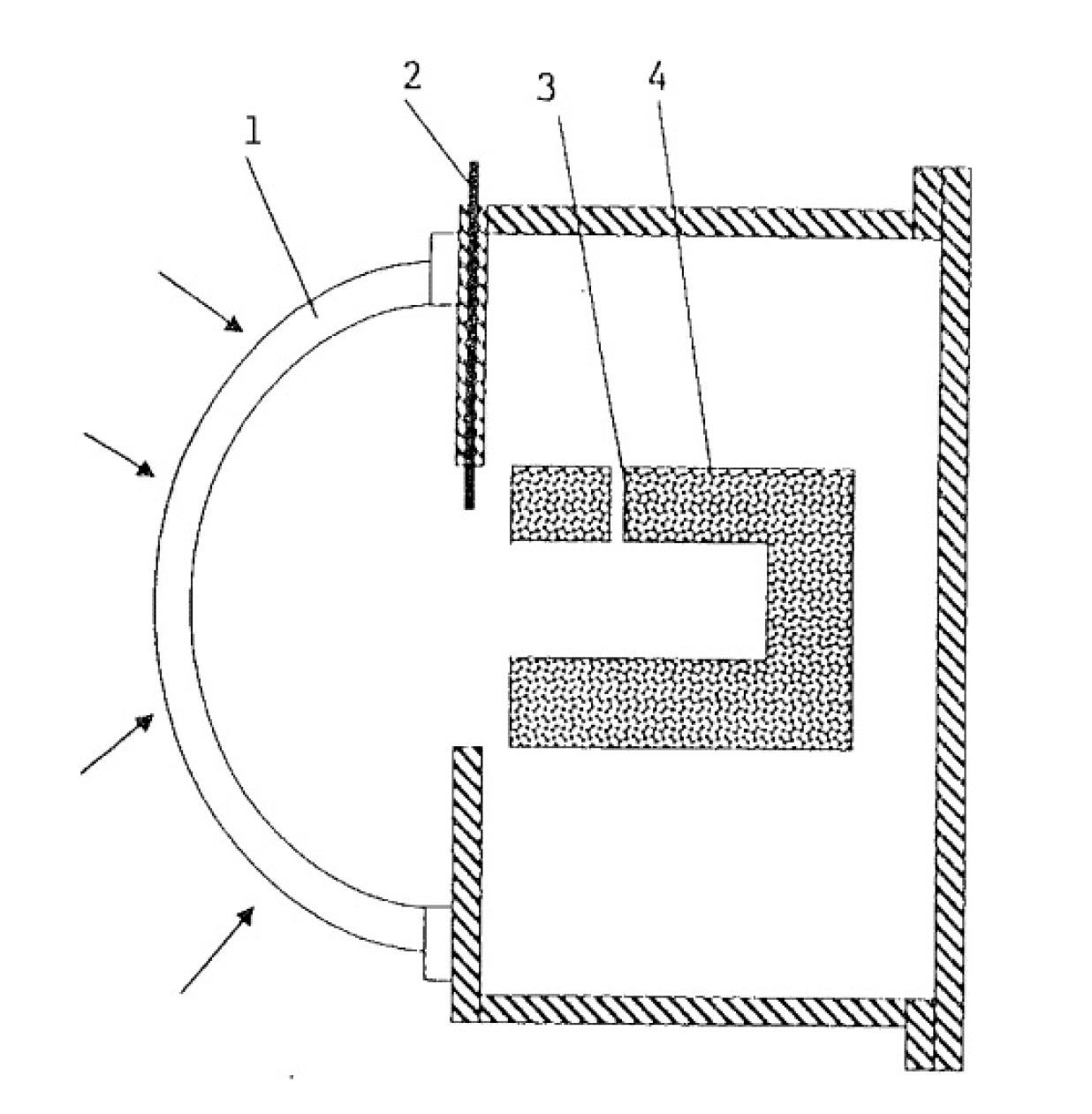
  114. Wang, Y.; Liu, Q.; Sun, J.; Lei, J.; Ju, Y.; Jin, H. A new solar receiver/reactor structure for hydrogen production. Energy Convers. Manag. 2017, 133, 118–126. [Google Scholar] [CrossRef]
  115. Liu, Q.; Wang, Y.; Lei, J.; Jin, H. Numerical investigation of the thermophysical characteristics of the mid-and-low temperature solar receiver/reactor for hydrogen production. Int. J. Heat Mass Transf. 2016, 97, 379–390. [Google Scholar] [CrossRef]
  116. Z’Graggen, A.; Steinfeld, A. Hydrogen production by steam-gasification of carbonaceous materials using concentrated solar energy–V. Reactor modeling, optimization, and scale-up. Int. J. Hydrog. Energy 2008, 33, 5484–5492. [Google Scholar] [CrossRef]
  117. Z’Graggen, A.; Haueter, P.; Trommer, D.; Romero, M.; De Jesus, J.C.; Steinfeld, A. Hydrogen production by steam-gasification of petroleum coke using concentrated solar powe – II Reactor design, testing, and modeling. Int. J. Hydrog. Energy 2006, 31, 797–811. [Google Scholar] [CrossRef]
  118. Z’Graggen, A.; Haueter, P.; Maag, G.; Vidal, A.; Romero, M.; Steinfeld, A. Hydrogen production by steam-gasification of petroleum coke using concentrated solar power–III. Reactor experimentation with slurry feeding. Int. J. Hydrog. Energy 2007, 32, 992–996. [Google Scholar] [CrossRef]
  119. Bader, R.; Bala Chandran, R.; Venstrom, L.J.; Sedler, S.J.; Krenzke, P.T.; De Smith, R.M.; Banerjee, A.; Chase, T.R.; Davidson, J.H.; Lipiński, W. Design of a solar reactor to split CO2 via isothermal redox cycling of Ceria. J. Sol. Energy Eng. 2015, 137, 031007. [Google Scholar] [CrossRef]
  120. Krueger, K.R.; Davidson, J.H.; Lipinski, W. Design of a new 45 kWe high-flux solar simulator for high-temperature solar thermal and thermochemical research. J. Sol. Energy Eng. 2011, 133, 011013. [Google Scholar] [CrossRef] [Green Version]
  121. Krueger, K.R.; Lipinski, W.; Davidson, J.H. Operational performance of the University of Minnesota 45 kWe high-flux solar simulator. J. Sol. Energy Eng. 2013, 135, 044501. [Google Scholar] [CrossRef]
  122. Kogan, A.; Kogan, M. The tornado flow configuration – an effective methof for screening of a solar reactor window. J. Sol. Energy Eng. 2002, 124, 206–214. [Google Scholar] [CrossRef]
Figure 1. Schematic representation of the difference between directly and indirectly irradiated reactors/receivers. Reprinted from [6] with permission from Elsevier.
Processes 08 00308 g001
Figure 2. Schematic representation of the indirectly heated solar receiver/reactor designed by Piatkowski et al. Reprinted from [18] with permission from Elsevier.
Processes 08 00308 g002
Figure 3. Schematic representation of the “snake-like” tubular reactor/receiver for biomass gasification with supercritical water proposed by Chen et al. Modified from [23] with permission from Elsevier.
Processes 08 00308 g003
Figure 4. Reactor (a) and detail of the absorber (b) configuration proposed by the Weizmann Institute of Science. Reprinted with permission from [32]. Copyright (2006) American Chemical Society.
Processes 08 00308 g004
Figure 5. Volumetric reactor/receiver for solar cracking. Reprinted from [46] with permission from Elsevier.
Processes 08 00308 g005
Figure 6. Reactor/receiver configuration for the direct thermolysis of water (1, Pyrex window; 2, silica tube for quenching; 3, H2O feed section; 4, insulating brick and cavity). Reprinted from [60] with permission from Elsevier.
Processes 08 00308 g006
Figure 7. Scheme of the receiver/reactor designed by Melchior et al. Reprinted from [25] with permission from Elsevier.
Processes 08 00308 g007
Figure 8. Schematics of the SurroundSun reactor receiver for (a) temperature swing and (b) isothermal operation. Reprinted from [111] with permission from Elsevier.
Processes 08 00308 g008
Figure 9. (a) Comparison between the traditional solar concentrator structure (top) and new solar concentrator structure (bottom); (b) reactor/receiver tube with variable diameter. Reprinted from [114] with permission from Elsevier.
Processes 08 00308 g009
Figure 10. Sectional view of the spherical cavity reactor proposed by Houaijia et al. Reprinted from [4] with permission from Elsevier.
Processes 08 00308 g010
Figure 11. Scheme of the reactor configuration proposed by Z’Graggen and co-workers. Reprinted from [116] with permission from Elsevier.
Processes 08 00308 g011
Figure 12. Indirectly heated solar reactor/receiver for water-splitting redox cycle on ceria (top) and detail of the reactive element. Reprinted from [119] with permission from ASME.
Processes 08 00308 g012
Figure 13. Reactor configuration analyzed by Kogan and Kogan. Reprinted from [122] with permission from ASME.
Processes 08 00308 g013

