Article

Simulation of Solid Oxide Fuel Cell Anode in Aspen HYSYS—A Study on the Effect of Reforming Activity on Distributed Performance Profiles, Carbon Formation, and Anode Oxidation Risk

1
Department of Chemical Engineering, Curtin University, Bentley 6102, Australia
2
Energy and Bioproducts Research Institute (EBRI), School of Engineering and Applied Science, Aston University, Birmingham B4 7ET, UK
*
Author to whom correspondence should be addressed.
Processes 2020, 8(3), 268; https://doi.org/10.3390/pr8030268
Submission received: 11 November 2019 / Revised: 21 February 2020 / Accepted: 24 February 2020 / Published: 27 February 2020
(This article belongs to the Special Issue Modelling and Process Control of Fuel Cell Systems)

Abstract

:
A distributed variable model for solid oxide fuel cell (SOFC), with internal fuel reforming on the anode, has been developed in Aspen HYSYS. The proposed model accounts for the complex and interactive mechanisms involved in the SOFC operation through a mathematically viable and numerically fast modeling framework. The internal fuel reforming reaction calculations have been carried out in a plug flow reactor (PFR) module integrated with a spreadsheet module to interactively calculate the electrochemical process details. By interlinking the two modules within Aspen HYSYS flowsheeting environment, the highly nonlinear SOFC distributed profiles have been readily captured using empirical correlations and without the necessity of using an external coding platform, such as MATLAB or FORTRAN. Distributed variables including temperature, current density, and concentration profiles along the cell length, have been discussed for various reforming activity rates. Moreover, parametric estimation of anode oxidation risk and carbon formation potential against fuel reformation intensity have been demonstrated that contributes to the SOFC lifetime evaluation. Incrementally progressive catalyst activity has been proposed as a technically viable approach for attaining smooth profiles within the SOFC anode. The proposed modeling platform paves the way for SOFC system flowsheeting and optimization, particularly where the study of systems with stack distributed variables is of interest.

1. Introduction

Fuel cells convert the chemical energy in fuel directly into electricity and heat, without combustion, leading to high efficiencies with low or even zero emissions. The SOFC is becoming a mature technology and can make the commercial breakthrough if cost targets can be met by achieving cost reductions through volume manufacturing, improved lifespan/performance, and lower cost materials [1,2,3]. Research and development in the last twenty years have led to significant advances in all areas of the technology including cell, seal, interconnect, and stack design, as well as peripheral components and the entire balance of plant (BoP) [4,5]. Manufacturing achievements have led to defect identification and minimization, quality control, and scale-up of stack components and the entire stack assembly manufacture.
The SOFC system is appropriate to operate on a pipeline fuel such as reticulated natural gas with its well-established supply infrastructure throughout the world. For such a fuel, minimal fuel processing is required, which includes desulphurization of the fuel to remove sulphur compounds that are naturally present in the hydrocarbon fuel source and those that are added as odorants to meet legislative requirements such as for natural gas, propane, and LPG for domestic applications. The preprocessing also includes a level of conversion of the hydrocarbon fuel, conventionally known as prereforming, which functions to convert the hydrocarbon feed such as natural gas to a hydrogen-rich mixture or a methane-rich mixture depending on the type of anode in the SOFC stack, i.e., noninternal reforming or internal reforming type. For an internal reforming type SOFC, where methane can be converted by steam reforming on the anode, it suffices to prereform the fuel to a level where all higher hydrocarbons (C1+) are converted leading to a mixture of methane, hydrogen, and carbon oxides with little or no conversion of methane [6,7]. For a noninternal reforming type SOFC, all hydrocarbon components including methane need to be fully converted to a mixture of hydrogen and carbon oxides. Owing to its high electrical efficiency, the SOFC technology results in reduced emissions of CO2 and is practically noise free. Furthermore, it is free of NOx emissions due to its relatively low operating temperatures. The SOFC system is particularly attractive as a combined heat and power generation (CHP) system, since the waste heat generated can be used to supply heat to a hot-water system which can be interfaced to the SOFC system [8].
A system-level flowsheet model of the SOFC system including the complete BoP is a useful platform for simulating the performance of the plant and for sizing of individual components of the BoP. Commercially available process simulation software such as Aspen Plus or Aspen HYSYS, PRO/II, etc., contains extensive thermodynamic and physical properties database and includes in-built modules for a number of components which are commonly used in a process plant, such as heat-exchangers of various types, reactors of various types, compressors, pumps, valves, separating columns, tanks, mixers, etc. It allows for energy optimization via heat and work integration of system components. However, it does not include a module for fuel cell reactions, i.e., it cannot directly account for the electrochemical reactions involving ions and electrons. There are two approaches for modeling SOFC-based systems with commercial process simulators. In one approach, the SOFC model is developed in a separate platform such as FORTRAN, VB, C++, MATLAB, etc. and then linked to the process simulator [9,10,11,12,13,14,15]. In another approach, the SOFC reactions are modeled using the equilibrium reactor module GIBBS [16,17]. Anderson et al. [17] modeled the SOFC as a combination of an isothermal plug flow reactor (PFR) module, to account for methane reforming kinetics on the anode, and a GIBBS reactor for the fuel cell reactions of hydrogen and CO oxidation. However, this was not a system-level model and focused on reactions and mass transport processes at the cell level. Using established theoretical and/or empirical correlations from literature, they tested the validity of their model by comparing their simulation results with those of others reported in the literature. Two main drawbacks of this work are the assumptions of isothermal conditions for internal reforming and use of a GIBBS reactor for the fuel cell reactions. In a real system the SOFC stack does not operate in an isothermal mode. There are two opposing contributions to stack temperature profiles in the case of an internal reforming anode. The endothermic steam reforming reaction absorbs heat from the gas stream which results in cooling of the stack and the fuel cell reaction(s) release heat which results in heating of the stack; the net effect is determined by the extents of these reactions.
A conversion reactor is more appropriate for representing the fuel oxidation reactions by setting the percent conversion equal to fuel utilization. An equilibrium approach using the GIBBS reactor does not allow setting of the reaction conversion to match fuel utilization. In this work, the internal reforming of methane via steam reforming and the accompanying water-gas shift (WGS) reaction is modeled via the PFR module with the kinetic expressions from literature [18,19] and the fuel cell reactions are modeled using the conversion reactor where the conversion is linked to the fuel utilization value calculated in a spreadsheet block. Another feature of the current work is that unlike the work of Anderson et al. [17], where the PFR is modeled as an isothermal reactor, in this work the energy stream of the PFR is linked to the cell in the spreadsheet block which calculates the heat generated by the fuel cell reaction and is available as reaction heat in a direct internal reforming SOFC. The axial temperature profile created in the PFR is therefore, representative of the temperature profile on an SOFC anode with direct internal reforming, as the coupling of the endothermic methane steam reforming (MSR) reaction and accompanying mildly exothermic WGS reaction with heat available from the fuel cell reaction is appropriately captured with this approach. The corresponding composition profile under current load cannot be generated within the PFR module as this module only works with kinetic schemes and it is not possible to add the fuel cell reactions to the PFR as conversion reactions based on fuel utilization. An option to include the reaction kinetics of the electrochemical oxidation of hydrogen is also not available in the software. Nevertheless, the reaction extents and accompanying heat exchanges can be calculated in the spreadsheet module and linked to the PFR module. Firstly, this allows generation of open-circuit composition profiles of the internally reformed gas which sets the boundary for the Nernst voltage profile under load, after accounting for the extents of the fuel cell reactions. Secondly, the current density and composition profiles can be calculated within the spreadsheet block using appropriate correlations.
Previous work [9,10,11,12,13,16] largely focused on the issues that can predict and improve the fuel cell operation in terms of current generation and voltage losses. For instance, the effect of air flow rate, steam to carbon ratio (S/C), current density, fuel utilization (Uf), inlet temperatures, or operating pressure have been extensively investigated. By contrast, in this work we have mainly focused on an analysis of processes that significantly affect anode performance and lifetime and consequently impact on the SOFC system as a whole. We analyzed anode performance for various levels of reforming activity. Three cases are considered: (i) Full reforming activity, (ii) 1/3rd reforming activity, and (iii) 1/6th reforming activity. Reduced reforming activity may be the result of engineered design [20] or may result from progressive degradation of the anode from poisoning or sintering due to nickel coarsening over the useful life of the stack [4], which extends the reaction zone and requires more of the anode segment from the leading edge to fully convert methane. Reforming kinetics reported by Ahmed and Föger [18] and WGS reaction kinetics reported by Tingey [19] were employed as the reaction rate details for PFR, leading to 1D pseudo-homogeneous results. The three different levels of activity were assigned by reducing the Arrhenius factor in the rate expression by the reduction factors 0.33 (~1/3rd) and 0.67 (~1/6th). In physical terms this signifies loss of reforming activity by poisoning or sintering. For these levels of activity, we assess the anode oxidation risk and carbon formation potential on the anode, both of which have severe life-limiting consequences on the anode [7].
This paper contributes to the SOFC research considering its two novel contents including; (i) the novel simulation methodology: The simulation approach proposed for complicated internal reforming SOFC process offers simplicity and calculation speed without compromising the internal operations details. This is of particular interest for SOFC system modeling and design where several operational concepts including heat/mass transfer and electrochemical and fuel reformation reactions interactively occur at wide time and length scales. (ii) The understanding of distributed reformation potentials in controlling SOFC performance profiles. The incremental reformation process is demonstrated to be a promising strategy to moderate the undesirable gradients of SOFC internal profiles. This is promising to achieve higher homogeneity in temperature and concertation profiles inside the SOFC stack that subsequently offers enhanced current and voltage profiles. This is crucially important for SOFC efficiency and durability. In this paper, we demonstrate internal fuel reformation as an opportunity not only for heat integration and external reformer cost reduction but also for thermal management goals that eventually results in fuel cell longevity.

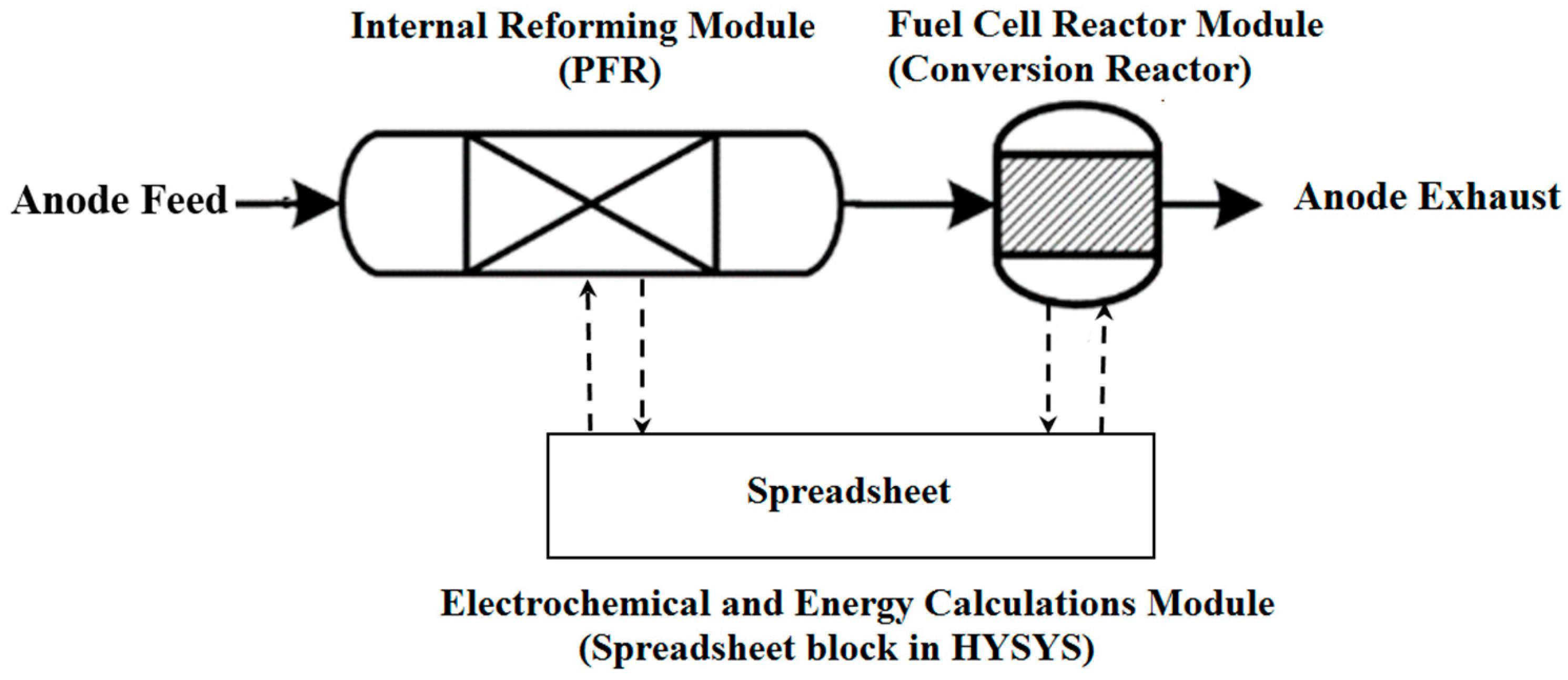
2. Simulation Methodology

The SOFC stack is simulated in the following way: Internal reforming of methane on the SOFC anode is modeled in a PFR module, using the reforming kinetics of Ahmed and Föger [18] and the WGS reaction kinetics of Tingey [19]. The electrochemical conversion of hydrogen and carbon monoxide are modeled as chemical conversions in a conversion reactor module. The associated electrical aspects including cell voltage, air utilization, and fuel utilization at a given operating current are calculated in a spreadsheet tool of Aspen HYSYS. The spreadsheet block in Aspen HYSYS is essentially an Excel-based spreadsheet with features of exporting data to and importing data from other modules of the flowsheet. This provides facility for post-processing of the calculated or entered values of the process variables. Computations of cell voltage entailing calculations of electrical losses, both ohmic and overpotential using empirical correlations [21] and calculation of Nernst voltage from the concentrations of the reacted gas are carried out in the spreadsheet, with compositions imported from the PFR module. Similarly, the sum of electrical losses and entropy change, after allowing for losses to the surroundings from the stack, is calculated and this value is exported to the energy stream linked to the PFR, as heat available for direct internal reforming.
The average stack operating temperature is obtained by a trial-and-error method. An average stack temperature is assumed for calculating Nernst voltage, operating voltage, and electrical losses. The assumed temperature is then compared to the value returned by the PFR, which simulates internal reforming and utilizes heat generated from the fuel cell reaction to compute the temperature profile within the fuel cell and the composition profile of the internally reformed fuel. The amount of heat generated, i.e., the electrical and entropy losses are calculated at the assumed average temperature. These steps are iterated until agreement is reached between the assumed average cell temperature and the calculated average cell temperature.
The composition of utilized gas is obtained by matching the degree of conversion in the conversion reactor, with the fuel utilization level calculated in the spreadsheet, based on fuel flow rate and operating current. Since the electrochemical conversion of H2 and CO are modeled as combustion reactions, there is a temperature rise in the reactor due to the exothermicity of the combustion reactions. Since the exothermicity of the fuel cell reactions have already been accounted for by calculating the electrical losses and entropy change of the fuel cell reaction and entering this value as heat input to the internal reforming PFR, temperature rise in the conversion reactor is suppressed by use of the HYSYS object SET, to set the temperature of the stream leaving the conversion reactor to be the same as the temperature of the stream leaving the PFR.
Figure 1 and Table 1 show the integration of the modules representing the anode operation and the set of equations used in the calculation of all distributed variables within the stack—temperature, current density, and composition of all chemical species on the anode side.
The reactions taking place in the reaction modules, shown in Figure 1, are as follows. Two parallel reactions take place in the internal reforming module (PFR) including MSR and WGS, presented by Equations (1) and (2), respectively:
CH4 + H2O = CO + 3H2
CO + H2O = CO2 + H2
Two parallel electrochemical reactions take place in the fuel cell reactor module (conversion reactor). The main reaction is hydrogen oxidation (Equation (3)) that may occur with the CO oxidation (Equation (4)), simultaneously.
H2 + 0.5O2 = H2O
CO + 0.5O2 = CO2

3. Results and Discussion

The base case is a system operating at 65% fuel utilization. Input parameters for the base case simulation and also estimated results returned by the flowsheet calculations are presented in Table 2 and Table 3, respectively.

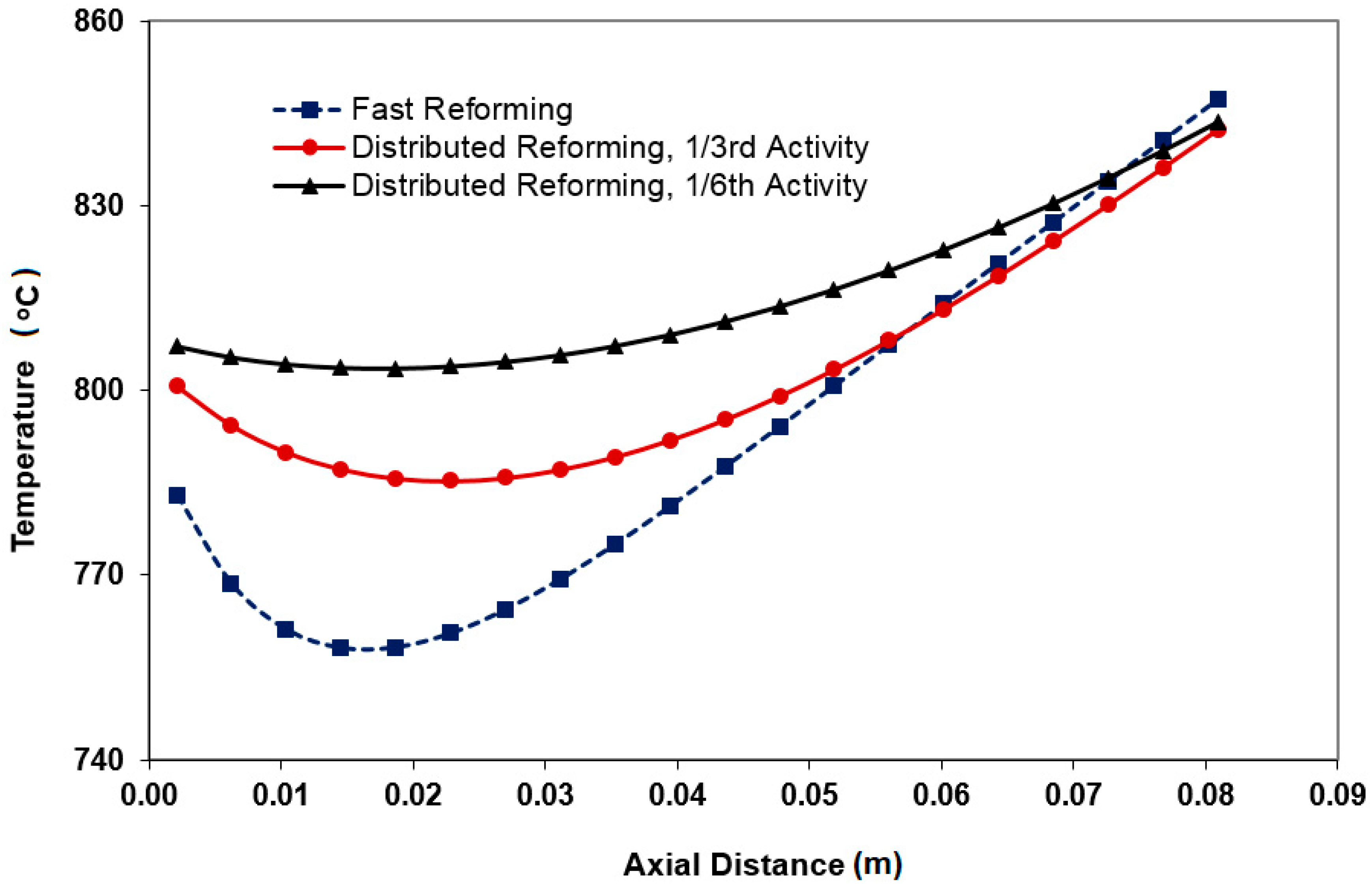
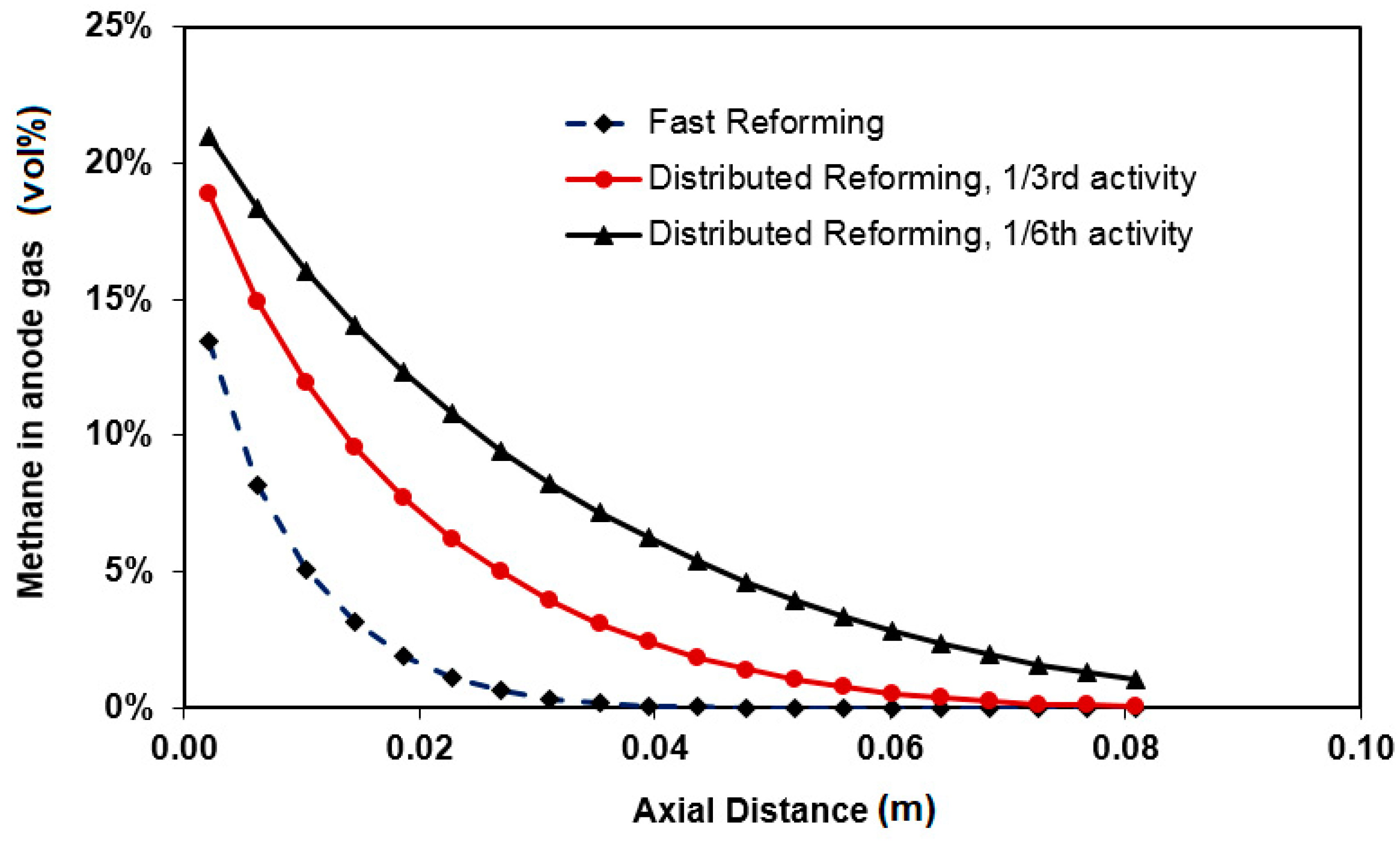
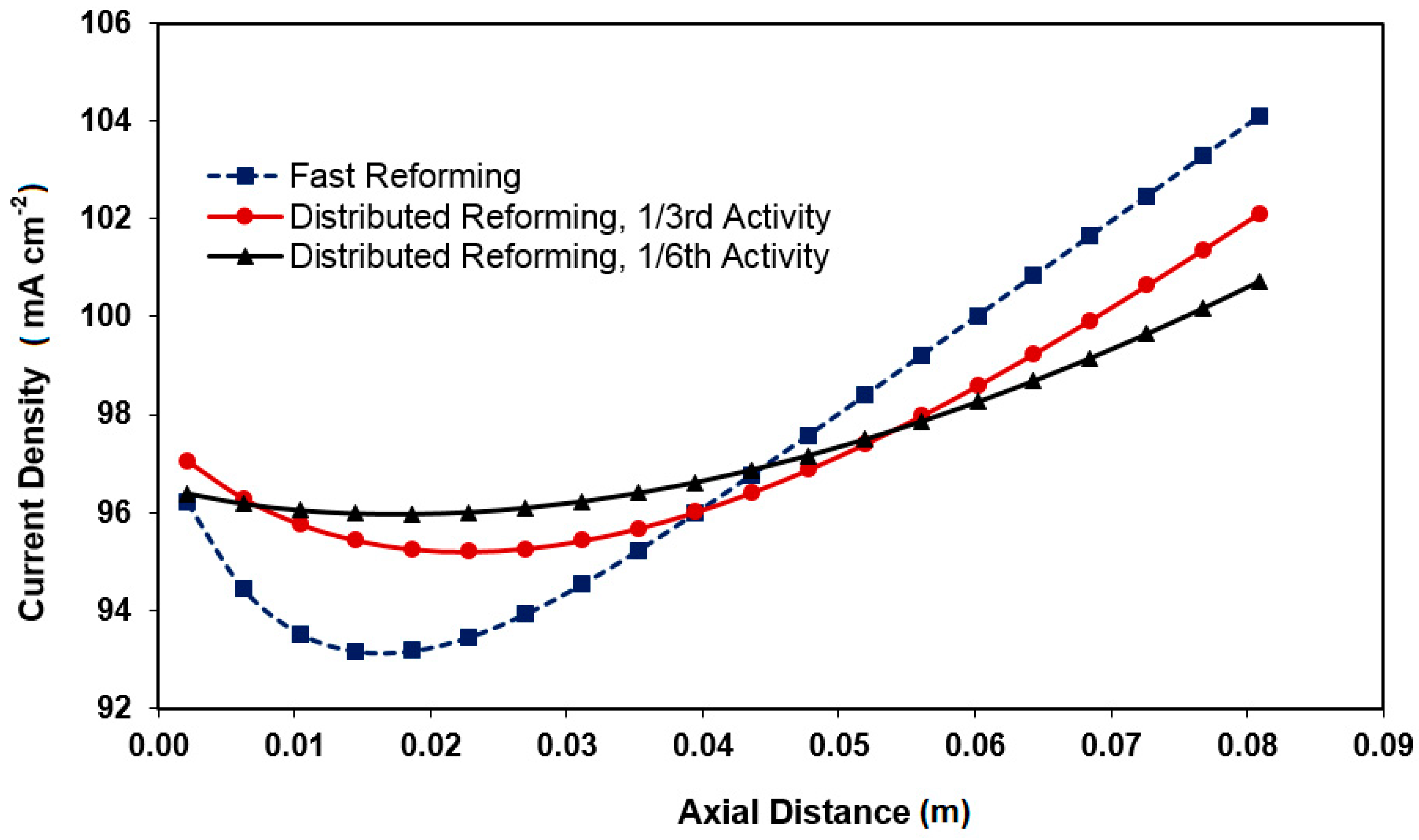
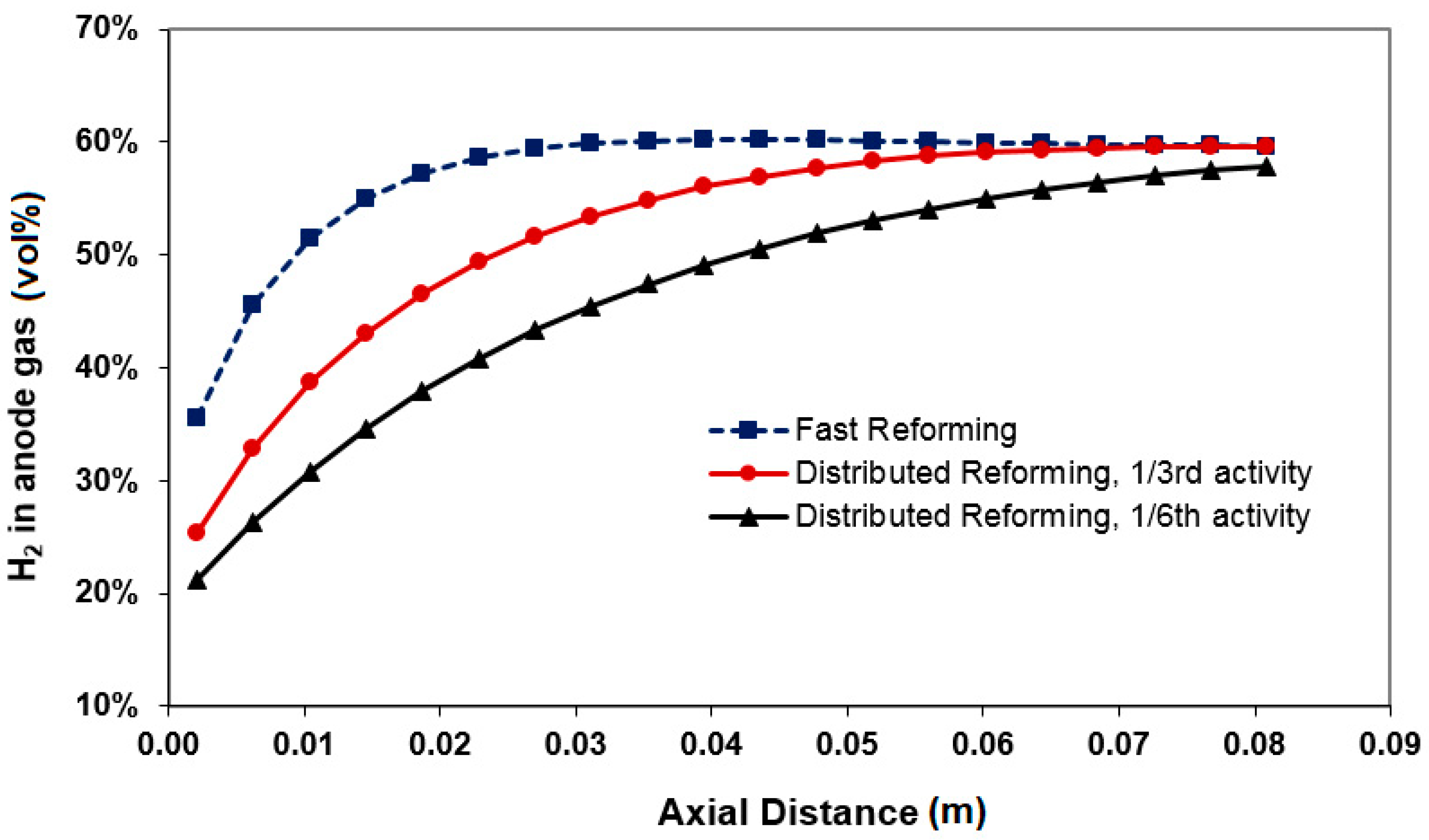
3.1. Distributed Profiles

A high degree of internal reforming of methane is desirable as it reduces the prereformer size/cost and contributes to the cooling of the cell and therefore, reduces the cooling air flow requirement. However, the internal fuel reformation process may undesirably cause higher gradients in the distributed variables profiles. Stack operation homogeneity is of crucial importance from both efficiency and lifetime viewpoints. Figure 2 shows when the kinetics of reforming is too rapid, the cell temperature drops sharply near the cell inlet preventing an even distribution of current density and temperature. The steep temperature gradient is caused by the cooling impact associated with the endothermic steam reforming of methane on the anode. Figure 3 shows the reforming in this case is so fast that it is completed within the first 40% of the cell. Clearly, the maximum temperature gradient can be reduced if the sharp drop in temperature can be avoided, improving all temperature-dependent profiles including species concentration, current density, and overpotentials distributions, all of which have interacting effects. An effective way of achieving this objective is by using catalysts with lower overall reforming activity in anode and/or designing an anode with progressively increasing local activity along the cell length. A reduction of the anode activity to 1/3rd of that of the fast reforming anode results in a relatively uniform temperature profile as shown in Figure 2.
A key technical question is whether the fuel reformation should be fully accomplished in the first half of the cell length. If not, there are significant opportunities to design anode reforming activity targeting a more homogenous operation. Accordingly, the objective of achieving smoother temperature profiles in the operating cell must also be assessed from another viewpoint. The activities are compared to the basis case activity (fast reformation). For instance, 1/3rd activity means 66% less activity (lower rate) compared to the basis case. We have adjusted this via E (activation energy value) adjustment in the simulations. With activities lower than the basis case, the catalyst still may offer sufficient reformation as the methane consumption (Figure 3) and hydrogen generation profiles show. The speed of reformation, however, is declined while it is compensated by residence time (axial length). This is the distributed conversion in contrast to the sharp conversion seen in basis case. To further reduce the temperature differential, an anode with a reforming activity 1/6th of that of the base case fast reforming anode is considered. This results in a more uniform temperature profile, Figure 2, but comes at a cost of increasing methane slip as shown in Figure 3. While a more homogenous electrochemical reactor is achievable under distributed/progressive reforming conditions, an immediate concern relevant to the reduced activity is the possibility of reduction in the generated current due to less local H2 availability in the first 30%–40% of the cell length. In order to assess this rigorously, the overall current produced over the cell surface must be calculated via integration of the local currents. Since no variation of current in cell width direction is assumed, that is a reasonable assumption for co-flow cell, two-dimensional integration can be replaced by one dimensional integration over the cell length. In such a case, therefore, the modeling approach proposed in this paper suffices. The surface under current density profiles in Figure 4 compares the total current production under different reforming approaches. Even though current production considerably drops in the cell inlet region when fast reforming occurs, the overall current production variation for fast and slow reformation activities can be reasonably ignored, indicating that cell efficiency will not be compromised for homogeneity.
Methane reforming profile (Figure 3) gives an indication of how the anode exhaust stream might be post-processed. In a fast reforming method, methane is completely consumed inside the stack leaving anode tail gas mainly including, hydrogen, CO, and a significant amount of steam. In such a case anode gas recycling is an appropriate process strategy. For slow/distributed fuel reforming, anode tail gas might contain some methane and less hydrogen and CO compared to the fast reforming. This can be understood by interpretation of methane and current profiles simultaneously. As current generations are equal, the H2 consumption in all cases are almost the same. For a given methane rate at inlet, therefore, higher methane fraction in cell outlet indicates lower amount of hydrogen and CO. This becomes even more considerable for an activity as low as 1/6th of the base case. Therefore, an after-burner can be designed in the system to achieve high quality heat from the tail gas. It may be concluded that the progressive fuel reforming offers some advantage for a CHP system in which both high quality heat and homogenous stack performance are desirable.
Stack exhaust temperature is reduced with progressive reforming activity compared to fast reforming, but the stack temperature profile for most of the anode length is higher as shown in Figure 2. While the latter is expected due to less steeper cooling along the cell, the reduction in stack exhaust temperature can be explained from a consideration of the associated current density profile. As shown in Figure 4, the current density profile is steepest for the fast reforming case resulting in higher joule heating effect. A lower joule heating effect results in lower increase in temperatures for the distributed reforming cases, to the point that the temperature at the end of the cell is lower for distributed reforming, even though the temperatures near the inlet are higher. A more uniform current density profile results in the case of lower reforming activity as expected which is beneficial from the point of stress reduction.

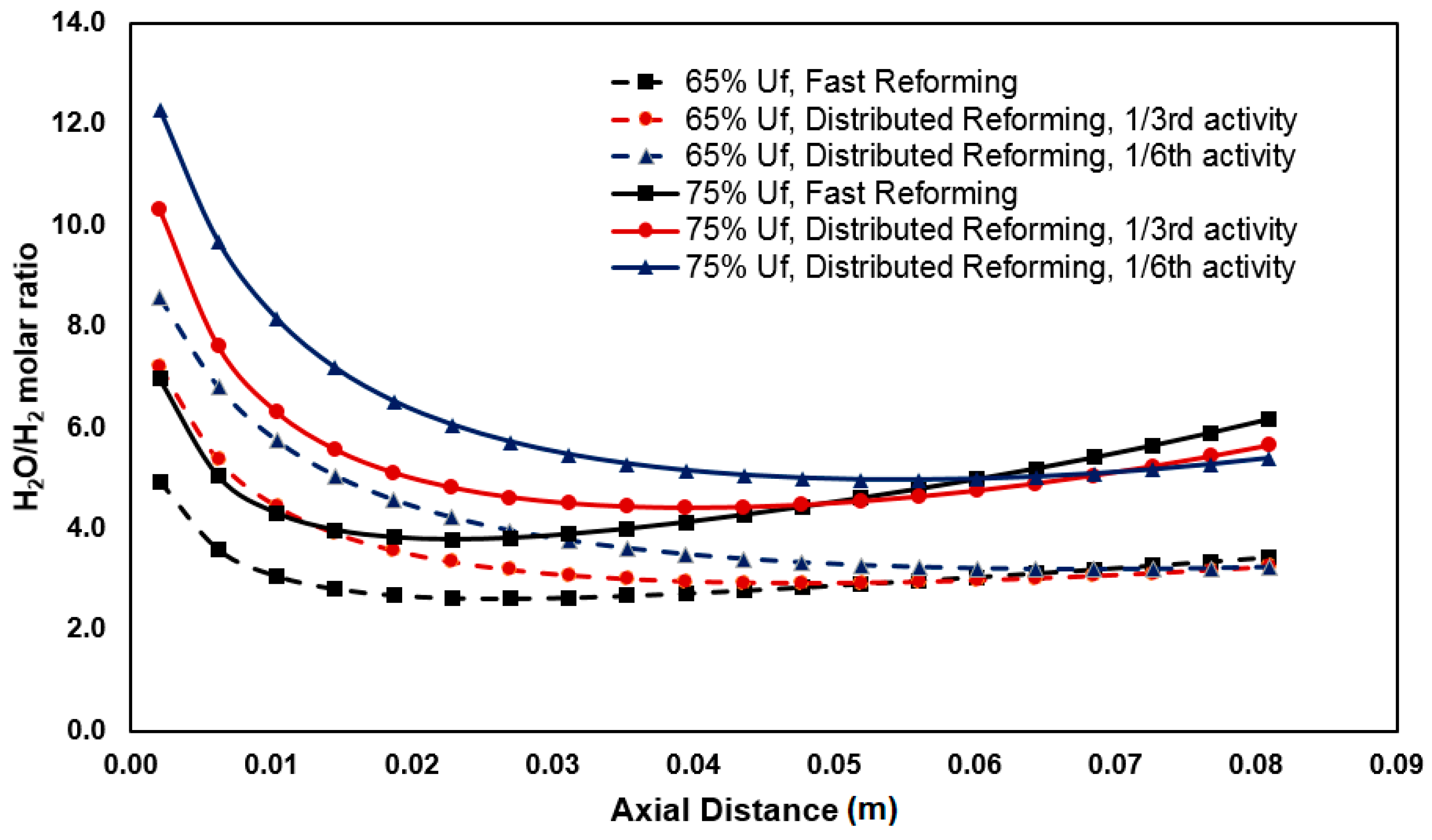
3.2. Anode Oxidation

The SOFC anode is susceptible to oxidation by steam in the reaction mixture according to Equation (5):
N i + 2 H 2 O = N i ( O H ) 2 + H 2
In this paper, anode oxidation risk is determined on the basis of industrial experience [22] with nickel-based catalysts, where it reported finding that steam-to-hydrogen ratios greater than 6–8 increases the risk of nickel oxidation in nickel-based steam reforming catalysts. Analyses, therefore, are based on the local partial pressures as a characteristic indicator rather than estimation of rate for reaction 5. Distributed profiles show that the risk of anode oxidation is particularly high at high fuel utilization, where the partial pressure of steam in the reaction mixture is high, i.e., at high pH2O/pH2. Anode oxidation risk profile along the length of the cell is shown in Figure 5 for 65% and 75% fuel utilization with three levels of reforming activity. Anode oxidation risk is highest at the anode inlet for internal reforming anodes where enough hydrogen has not been generated (Figure 6). The risk increases with slow reforming activity. At higher utilization, more hydrogen is utilized, further lowering the H2 content and increasing the H2O content, thereby increasing the risk of anode oxidation compared to lower utilization. In such a case, anode tail gas recycle may worsen the situation by introducing more steam upstream. This is an additional reason why tail gas in the slow internal reforming case is recommended to be burnt rather than being recycled. In general, anode gas recycling may change the pH2O and pH2 balance in favour of steam.

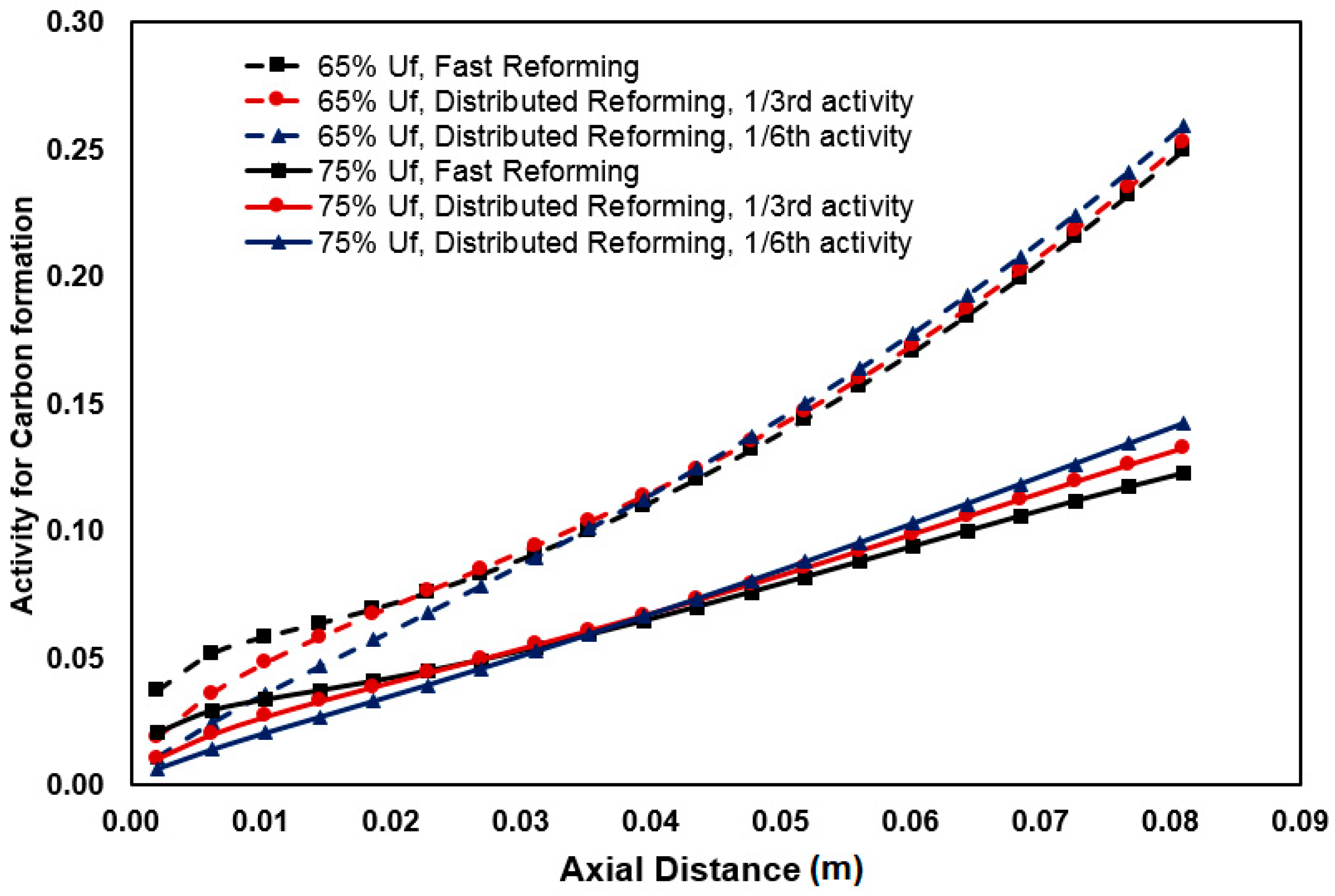
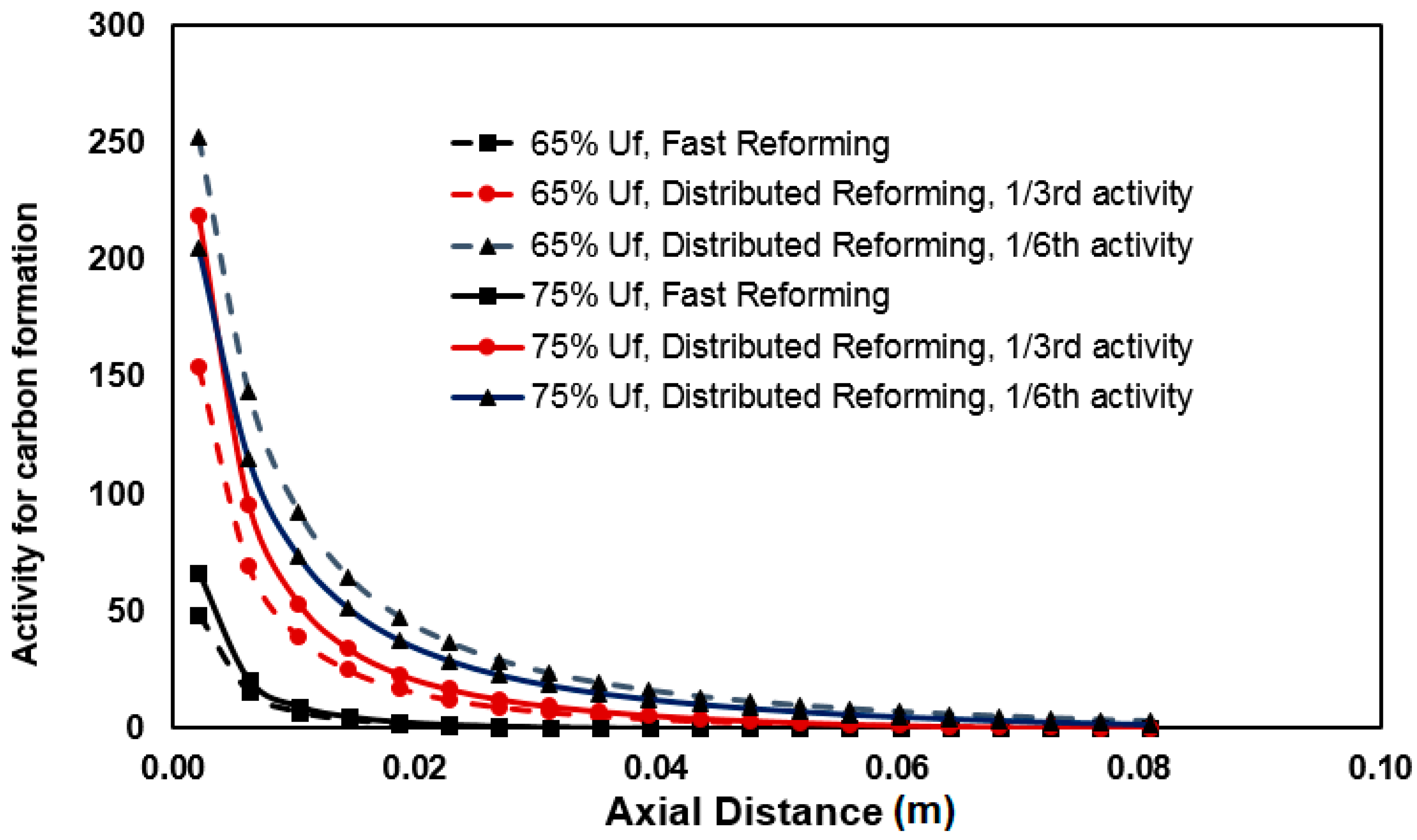
3.3. Carbon Formation

Carbon formation on the SOFC anode, as a challenging issue for SOFC degradation, might occur principally via two routes: Boudouard reaction and methane cracking. In this work, carbon formation activity is calculated based on the thermodynamical equilibrium estimated using the local temperature and compositions of the relevant species participating in the respective reactions. Carbon may form by cracking or dissociation of a methane molecule into carbon and hydrogen molecules according to the reaction in Equation (6):
C H 4 = C + 2 H 2
For this reaction, the carbon activity for dissociation of a methane ( a c d ) can be calculated by using Equation (7):
a c d = K c d p C H 4 ( p H 2 ) 2
The Boudouard or carbon disproportionation reaction can be presented as Equation (8):
2 C O = C + C O 2
Similar to the methane cracking, a carbon activity can be defined for Boudouard reaction ( a c b ) by using the local concentration/partial pressure of the gases involved, as presented in Equation (9):
a c b = K c b ( p C O ) 2 p C O 2
Simulated distribution of the carbon formation risks from Boudouard reaction and methane cracking are depicted in Figure 7 and Figure 8, respectively. Figure 7 shows that under the operational conditions used in this study and fuel utilization ranging from 65% to 75%, the probability of carbon formation through Boudouard reaction is low and well below 1 regardless of the fuel reforming pattern, i.e., fast or distributed reformation patterns. This is primarily due to the fact that this reaction is not thermodynamically benefited by the elevated temperature specifically above 700 °C. The trend along the anode length can be explained with respect to the CO and CO2 concentrations profiles and the anode thermal behaviour. The risk is relatively high at lower fuel utilization levels due to relatively higher and lower levels of CO and CO2, respectively, in the anode gas mixture and also lower local temperature, all enhancing the Boudouard reaction chance to occur. Note that according to Equation (9), at any given temperature, the higher the ratio of (pCO)2/pCO2, the higher the carbon activity. Near the inlet, CO is low, as methane reforming has not progressed much. Further down, the ratio depends on how much CO is formed by reforming and how much CO2 is formed by WGS (Equation (2)). The WGS equilibrium is also affected by the current draw, as the WGS equilibrium shifts to the right as more H2 are consumed by the hydrogen electrochemical oxidation reaction (Equation (3)). It will also be affected by electrochemical oxidation of CO to CO2, but the extent of this reaction is generally small, as this reaction is not as fast as H2 oxidation. Moreover, due to equal stoichiometry, this effect is accounted for by the WGS equilibrium reaction (Equation (2)). As the WGS reaction generates one mole of hydrogen per mole of CO, the electrochemical and chemical balance is unaffected whether the CO conversion is modeled as a WGS or as electrochemical oxidation. In a recent work [23], the effect of different reaction kinetics and equilibrium of the methane steam reforming reaction and WGS reaction were shown to have significant effect on the concentration profiles along the cell length. Temperature change along the cell length also affects the carbon activity as it changes the value of the equilibrium constant.
Figure 8 shows a very high risk of carbon formation by methane cracking near the anode inlet where methane concentration is high. The risk increases for lower fuel utilization and for slower reforming activity. The carbon formation activity is calculated based on thermodynamic equilibrium; in practice, whether carbon will be formed will depend on the kinetics of the reactions involved.

4. Conclusions

A model of a SOFC cell incorporating a 1D model of the anode has been developed in Aspen HYSYS. A salient feature of this model is its ability to predict simultaneous direct internal reforming on the anode and electrochemical reaction with these two reactions thermally integrated. In spite of being based on empirical correlations that makes modeling platform computationally efficient it successfully captures the distributed variables associated with stack level performance, particularly with respect to internal reforming kinetics and electrical performance. This has been achieved through interlinking of the in-built PFR module with a spreadsheet block inside the Aspen HYSYS environment. Cases for various levels of reforming activity have been compared to demonstrate the effect and relative advantages and disadvantages in terms of temperature and current density profiles. Two technically challenging aspects of SOFC operation: Anode oxidation risk and carbon formation potential have been evaluated. The methodology proposed in this paper is flexible to deploy more detailed fundamental correlations such as explicit equations based on exchange current.

Author Contributions

Conceptualization, K.A., A.A., and M.O.T.; methodology, K.A. and A.A.; software, K.A. and A.A.; validation, K.A. and A.A.; formal analysis, K.A., A.A., and M.O.T.; investigation, K.A., A.A., and M.O.T.; resources, M.O.T.; data curation, K.A. and A.A.; writing—original draft preparation, K.A., M.O.T., and A.A.; writing—review and editing, M.O.T., K.A. and A.A.; visualization, K.A. and A.A.; supervision, M.O.T.; project administration, M.O.T. All authors have read and agreed to the published version of the manuscript.

Funding

This research received no external funding.

Conflicts of Interest

The authors declare no conflict of interest.

References

  1. Gasik, M. Materials for Fuel Cells; Woodhead Publishing: Sawston, Cambridge, UK, 2008. [Google Scholar]
  2. Cooper, S.J.; Brandon, N.P. Chapter 1—An Introduction to Solid Oxide Fuel Cell Materials, Technology and Applications. In Solid Oxide Fuel Cell Lifetime and Reliability; Brandon, N.P., Ruiz-Trejo, E., Boldrin, P., Eds.; Academic Press: Cambridge, MA, USA, 2017; pp. 1–18. [Google Scholar]
  3. Wang, J.; Wang, H.; Fan, Y. Techno-Economic Challenges of Fuel Cell Commercialization. Engineering 2018, 4, 352–360. [Google Scholar] [CrossRef]
  4. Ahmed, K.; Föger, K. Perspectives in Solid Oxide Fuel Cell-Based Microcombined Heat and Power Systems. J. Electrochem. Energy Convers. Storage 2017, 14, 031005. [Google Scholar] [CrossRef]
  5. Lanzini, A.; Ferrero, D.; Santarelli, M. Energy System Analysis of SOFC Systems. In Advances in Medium and High Temperature Solid Oxide Fuel Cell Technology; Boaro, M., Salvatore, A.A., Eds.; Springer International Publishing: Cham, Switzerland, 2017; pp. 223–264. [Google Scholar]
  6. Van Biert, L.; Visser, K.; Aravind, P.V. Intrinsic methane steam reforming kinetics on nickel-ceria solid oxide fuel cell anodes. J. Power Sources 2019, 443, 227261. [Google Scholar] [CrossRef]
  7. Van Biert, L.; Godjevac, M.; Visser, K.; Aravind, P.V. Dynamic modelling of a direct internal reforming solid oxide fuel cell stack based on single cell experiments. Appl. Energy 2019, 250, 976–990. [Google Scholar] [CrossRef]
  8. CFCL Delivers Fuel Cell Components for 40 Integrated m-CHP Units. Available online: http://www.fuelcelltoday.com/news-archive/2013/october/cfcl-delivers-fuel-cell-components-for-40-integrated-m-chp-units/ (accessed on 20 May 2019).
  9. Amiri, A.; Vijay, P.; Tadé, M.O.; Ahmed, K.; Ingram, G.D.; Pareek, V.; Utikar, R. Solid oxide fuel cell reactor analysis and optimisation through a novel multi-scale modelling strategy. Comput. Chem. Eng. 2015, 78, 10–23. [Google Scholar] [CrossRef] [Green Version]
  10. Doherty, W.; Reynolds, A.; Kennedy, D. Simulation of a tubular solid oxide fuel cell stack operating on biomass syngas using aspen plus. J. Electrochem. Soc. 2010, 157, B975–B981. [Google Scholar] [CrossRef] [Green Version]
  11. Kupecki, J.; Badyda, K. SOFC-based micro-CHP system as an example of efficient power generation unit. Arch. Thermodyn. 2011, 32, 33. [Google Scholar] [CrossRef]
  12. Riensche, E.; Meusinger, J.; Stimming, U.; Unverzagt, G. Optimization of a 200 kW SOFC cogeneration power plant. Part II: Variation of the flowsheet. J. Power Sources 1998, 71, 306–314. [Google Scholar] [CrossRef]
  13. Tanim, T.; Bayless, D.J.; Trembly, J.P. Modeling a 5 kWe planar solid oxide fuel cell based system operating on JP-8 fuel and a comparison with tubular cell based system for auxiliary and mobile power applications. J. Power Sources 2014, 245, 986–997. [Google Scholar] [CrossRef]
  14. Amiri, A.; Vijay, P.; Tadé, M.O.; Ahmed, K.; Ingram, G.D.; Pareek, V.; Utikar, R. Planar SOFC system modelling and simulation including a 3D stack module. Int. J. Hydrogen Energy 2016, 41, 2919–2930. [Google Scholar] [CrossRef] [Green Version]
  15. Tang, S.; Amiri, A.; Tadé, M.O. System Level Exergy Assessment of Strategies Deployed for Solid Oxide Fuel Cell Stack Temperature Regulation and Thermal Gradient Reduction. Ind. Eng. Chem. Res. 2019, 58, 2258–2267. [Google Scholar] [CrossRef]
  16. Zhang, W.; Croiset, E.; Douglas, P.L.; Fowler, M.W.; Entchev, E. Simulation of a tubular solid oxide fuel cell stack using AspenPlusTM unit operation models. Energy Convers. Manag. 2005, 46, 181–196. [Google Scholar] [CrossRef]
  17. Anderson, T.; Vijay, P.; Tade, M.O. An adaptable steady state Aspen Hysys model for the methane fuelled solid oxide fuel cell. Chem. Eng. Res. Des. 2014, 92, 295–307. [Google Scholar] [CrossRef]
  18. Ahmed, K.; Foger, K. Kinetics of internal steam reforming of methane on Ni/YSZ-based anodes for solid oxide fuel cells. Catal. Today 2000, 63, 479–487. [Google Scholar] [CrossRef]
  19. Tingey, G.L. Kinetics of the Water—Gas Equilibrium Reaction. I. The Reaction of Carbon Dioxide with Hydrogen. J. Phys. Chem. 1966, 70, 1406–1412. [Google Scholar] [CrossRef]
  20. Aguiar, P.; Chadwick, D.; Kershenbaum, L. Modelling of an indirect internal reforming solid oxide fuel cell. Chem. Eng. Sci. 2002, 57, 1665–1677. [Google Scholar] [CrossRef]
  21. Ahmed, K.; Foger, K. An experimental and modelling study of the performance of a single-cell SOFC stack operating on mixtures of H2-CO-H2O-CO2. In Proceedings of the 4th European SOFC Forum, Oberrohrdorf, Switzerland, 30 June–3 July 2000; pp. 315–324. [Google Scholar]
  22. Twigg, M.V. Catalyst Handbook. CRC: Boca Raton, FL, USA, 1989. [Google Scholar]
  23. Ahmed, K.; Föger, K. Analysis of equilibrium and kinetic models of internal reforming on solid oxide fuel cell anodes: Effect on voltage, current and temperature distribution. J. Power Sources 2017, 343, 83–93. [Google Scholar] [CrossRef]
Figure 1. Schematic of integration of the internal reforming reaction modules and the fuel cell reactor module.
Processes 08 00268 g001
Figure 2. Temperature profiles for various levels of reforming activity.
Processes 08 00268 g002
Figure 3. Methane concentration profiles for different reforming activity.
Processes 08 00268 g003
Figure 4. Current density profiles for different levels of reforming activity and Uf = 65%.
Processes 08 00268 g004
Figure 5. Anode oxidation risk profile for different reforming activity at 65% and 75% fuel utilization.
Processes 08 00268 g005
Figure 6. Open-circuit hydrogen concentration profiles for different reforming activity.
Processes 08 00268 g006
Figure 7. Profile of carbon formation risk from Boudouard reaction for different reforming activity at 65% and 75% fuel utilization.
Processes 08 00268 g007
Figure 8. Profile of carbon formation risk from methane cracking for different reforming activity at 65% and 75% fuel utilization.
Processes 08 00268 g008
Table 1. Modeling approach for solid oxide fuel cell (SOFC) performance approximation.
Equations/ParametersComment
{ U f , m ˙ F u e l } = G i v e n Constant fuel utilization.
I a v = m ˙ F u e l U f ( n F ) Average current drawn based on given fuel rate and desired fuel utilization.
Q e l e c = ( I a v / n F ) ( Δ H r ) = m ˙ F u e l U f ( Δ H r ) Heat of electrochemical reaction for given fuel consumption, calculated in the spreadsheet block.
Δ T = ( Q e l e c ( m C p ) m i x ) Temperature change due to heat release from fuel oxidation.
C x , O C O ( l ) , T O C O ( l )
x ={H2, H2O, CO, CO2, CH4},
Open-circuit operation (OCO) composition and temperature profiles from the internal reforming module (PFR) based on MSR and WGS reaction kinetics.
T C C O ( l ) = T O C O ( l ) + Δ T Temperature profile for closed-circuit operation from corresponding open-circuit operation data.
C x , C C O ( l ) f ( C x , O C O ( l ) , U f ) Closed-circuit operation (CCO) composition profiles using fuel utilization.
I C C O ( l ) g ( T C C O ( l ) , C H 2 , O C O ( l ) ) Current density profile estimation from temperature distribution and open-circuit hydrogen concentration profile.
r M S R = k o exp ( E a / R T ) ( p C H 4 ) α ( p H 2 O ) β Kinetics of MSR; ko = 8542 mol/(m2bar1/2s), α = 0.85, β = −0.35, and Ea = 95 kJ/mol [18].
r R W G S = 7.6 × 10 4 exp ( 39.2 / R T ) p H 2 0.333 p C O 2 + 1.2 × 10 13 exp ( 78 / R T ) p H 2 0.5 p C O 2 Kinetics of the reverse WGS reaction reported by Tingey [19].
V = E O C V η I R Ω The cell voltage was calculated by deducting the voltage losses from the open-circuit Nernst voltage.
E O C V = E + R T n F ln ( p H 2 p O 2 0.5 p H 2 O ) Open-circuit Nernst voltage.
η = ( 1 / a ) I y U f z exp ( E b / R T ) Overpotential losses were calculated using an empirical equation [21]; a = 4.43, y = 0.77, z = -0.15, and Eb = 10,560 kJ/mol, determined by regression analysis of experimental measurement of cell overpotential at various current densities and fuel utilization at the three temperatures 750, 800, and 850 °C.
R Ω = ( t e / A ) exp ( B / T ) The cell ohmic resistance is independent of fuel utilization as expected [21], where te is the electrolyte thickness (µm) and A = 21,428 µm/Ω and B = 7776 K are constants, with their values determined empirically [21].
Table 2. Model input parameters for the base case simulation.
VariableValue
NG Flow Rate 5.4 SLM
Air Flow Rate300 SLM
Air Inlet Temperature to Stack810 °C
Fuel Utilization65%
S/C Ratio (at reformer inlet)2.25
Fuel Inlet Temperature to Stack810 °C
Note: SLM—Standard litres per minute, at 0 °C, 1 atm
Table 3. Estimated SOFC performance results.
VariableValue
Net Power1.3 kW
Net Electrical Efficiency38.6%
Stack Operating Current40.7 A
Operating Voltage0.67 V
Air Utilization11.4%
Average Stack Temperature 792.7 °C
Stack Exhaust Temperature847.4 °C
Nernst Voltage (Open-Circuit)0.993 V
Nernst Voltage (65% Uf) 0.900 V
Overpotential Losses0.173 V
Ohmic Resistance1.547 ohm-cm2
Methane Slip0.0%

