A Comprehensive Review and Technical Guideline for Optimal Design and Operations of Fuel Cell-Based Cogeneration Systems


Abstract
:1. Introduction
2. Overview of Fuel Cells and Cogeneration Systems
2.1. Fuel Cells: Working Principle and Types
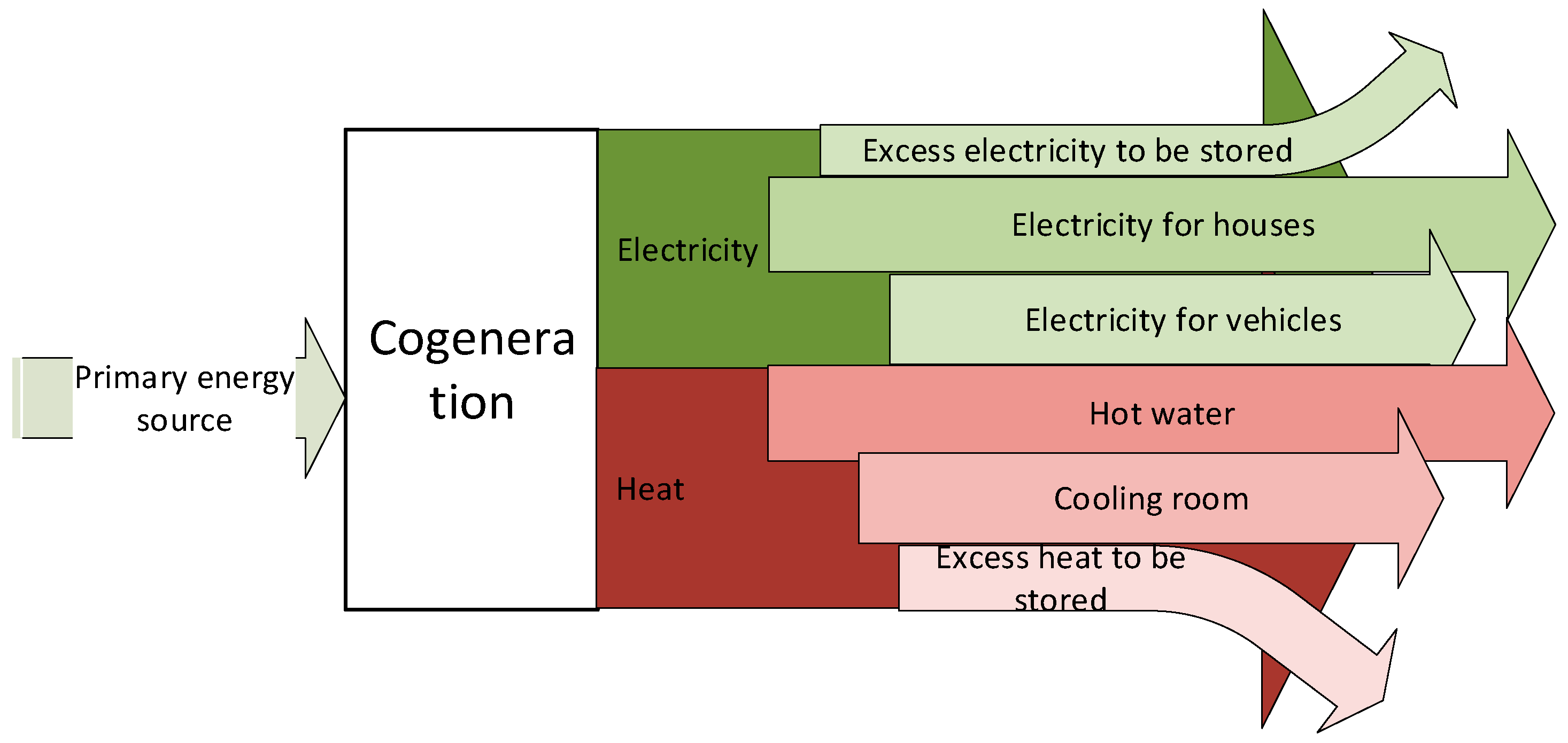
2.2. Cogeneration: System Components and Applications
3. Current Developments of the Fuel Cell-Based Cogeneration Systems
3.1. Research and Development Sector
3.2. Commercialization Sector
3.3. Governmental Support
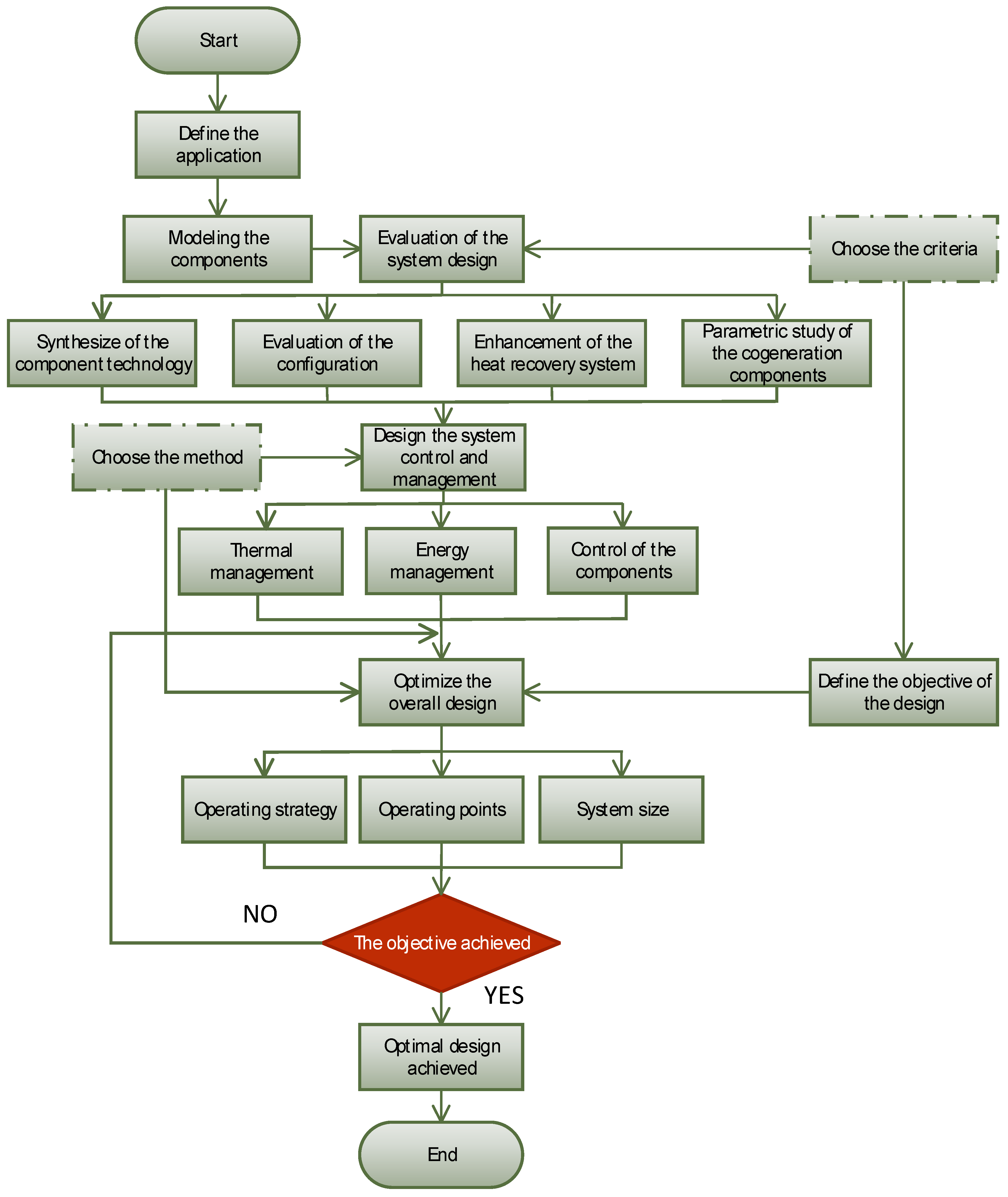
4. Designing a Fuel Cell-Based Cogeneration System
4.1. Modeling the Components
4.2. Choosing the Criteria for Evaluation
4.3. Evaluation of the System Design
4.4. System Control and Management
4.5. Optimization of the Overall Design
5. Summary of the Gathered Literature in the Past 5 Years
6. Future Directions of Fuel Cells Application in Energy Generation Systems
7. Conclusions
Author Contributions
Funding
Conflicts of Interest
Abbreviations/Symbols
| ACS | Annualized cost system |
| AFC | Alkaline fuel cell |
| ANGR | Annual natural gas reduction |
| ANN | Adaptive neural network |
| CCA | Colonial competitive algorithm |
| CHP | Combined heat and power |
| CO2E | Carbon dioxide emission |
| COP | Coefficient of performance |
| CR | Contribution ratio |
| CSS | Conventional separated system |
| DL | Doping level |
| DMFC | Direct methanol fuel cell |
| DRB | Durability |
| DSM | Direct search method |
| EAC | Estimated annual cost |
| ECO | Economic aspect |
| EES | Engineering equation solver |
| EFF | Efficiency |
| EI | Energy index |
| EMS | Energy management strategy |
| ENV | Environmental aspect |
| EO | Electric operation |
| ES | Energy saving |
| GHG | Greenhouse gas |
| HE | Heat-to-electric |
| HO | Heat operation |
| HT | High temperature |
| LCA | Life cycle analysis |
| LCIA | Life cycle integrated analysis |
| LCOE | Levelized cost of energy |
| LT | Low temperature |
| MCFC | Molten carbonate fuel cell |
| MED | Multi-effect distillation |
| MFC | Micro-bacterial fuel cell |
| MILP | Mixed integer linear programming |
| MINLP | Mixed integer non-linear programming |
| MO | Multi-objective |
| MOGA | Multi-objective genetic algorithm |
| MSE | Mass specific emission |
| NL | Nonlinear |
| NPC | Net present cost |
| NPV | Net present cost |
| OC | Operational cost |
| OOP | Optimal operating parameter |
| PAFC | Phosphoric acid fuel cell |
| PBT | Payback time |
| PEC | Primary energy consumption |
| PEMFC | Proton exchange membrane fuel cell |
| PES | Primary energy saving |
| PI | Performance index |
| PLR | Part load ratio |
| PP | Payback period |
| RTC | Real-time control |
| S/C | Steam to carbon ratio |
| SOFC | Solid oxide fuel cell |
| SP | Separated system |
| SPT | System payback time |
| SUCP | Sum of unit cost of products |
| SVR | Support vector regression |
| TCN | Technical aspect |
| TCR | Total cost rate |
| TED | Thermoelectric device |
| WWT | Wastewater treatment |
| T | Temperature |
| P | Pressure |
| m | Thermoelectric elements |
| K | Conductance |
| c1 | Regenerative losses |
| c2 | Heat-leakage losses |
| j | Current density |
| Ti | Inlet temperature of SOFC |
| εr | Regenerator effectiveness |
References
- Busu, M. The Role of Renewables in a Low-Carbon Society: Evidence from a Multivariate Panel Data Analysis at the EU Level. Sustainability 2019, 11, 5260. [Google Scholar] [CrossRef] [Green Version]
- Zhao, W.; Zou, R.; Yuan, G.; Wang, H.; Tan, Z. Long-Term Cointegration Relationship between China’s Wind Power Development and Carbon Emissions. Sustainability 2019, 11, 4625. [Google Scholar] [CrossRef] [Green Version]
- Frangopoulos, C.A. Cogeneration Technologies, Optimisation and Implementation. In Iet Energy Engineering; The Institution of Engineering and Technology: London, UK, 2017; Volume 87. [Google Scholar]
- Weng, G.-M.; Li, C.-Y.V.; Chan, K.-Y. Hydrogen battery using neutralization energy. Nano Energy 2018, 53, 240–244. [Google Scholar] [CrossRef]
- Weng, G.-M.; Li, C.-Y.V.; Chan, K.-Y. An Acid–Base Battery with Oxygen Electrodes: A Laboratory Demonstration of Electrochemical Power Sources. J. Chem. Educ. 2019, 96, 1701–1706. [Google Scholar] [CrossRef]
- Maffei, N.; Pelletier, L.; Charland, J.; McFarlan, A. An intermediate temperature direct ammonia fuel cell using a proton conducting electrolyte. J. Power Sources 2005, 140, 264–267. [Google Scholar] [CrossRef]
- Kordesch, K.; Simader, G. Fuel Cells and Their Applications; Wiley-VCH: Weinheim, Germany, 1996. [Google Scholar]
- Ramadhani, F.; Hussain, M.A.; Mokhlis, H.; Fazly, M.; Ali, J.M. Evaluation of solid oxide fuel cell based polygeneration system in residential areas integrating with electric charging and hydrogen fueling stations for vehicles. Appl. Energy 2019, 238, 1373–1388. [Google Scholar] [CrossRef]
- Al Moussawi, H.; Fardoun, F.; Louahlia, H. Selection based on differences between cogeneration and trigeneration in various prime mover technologies. Renew. Sustain. Energy Rev. 2017, 74, 491–511. [Google Scholar] [CrossRef]
- Arsalis, A. A comprehensive review of fuel cell-based micro-combined-heat-and-power systems. Renew. Sustain. Energy Rev. 2019, 105, 391–414. [Google Scholar] [CrossRef]
- Milcarek, R.J.; Ahn, J.; Zhang, J. Review and analysis of fuel cell-based, micro-cogeneration for residential applications: Current state and future opportunities. Sci. Technol. Built Environ. 2017, 1–20. [Google Scholar] [CrossRef]
- Isa, N.M.; Tan, C.W.; Yatim, A.H.M. A comprehensive review of cogeneration system in a microgrid: A perspective from architecture and operating system. Renew. Sustain. Energy Rev. 2018, 81, 2236–2263. [Google Scholar] [CrossRef]
- Murugan, S.; Horák, B. A review of micro combined heat and power systems for residential applications. Renew. Sustain. Energy Rev. 2016, 64, 144–162. [Google Scholar] [CrossRef]
- Ahmadi, P. Modeling, Analysis and Optimization of Integrated Energy Systems for Multigeneration Purposes; University of Ontario Institute of Technology: Oshawa, ON, Canada, 2013. [Google Scholar]
- Elmer, T. A Novel SOFC Tri-Generation System for Building Applications; University of Nottingham: Nottingham, UK, 2015. [Google Scholar]
- Ellamla, H.R.; Staffell, I.; Bujlo, P.; Pollet, B.G.; Pasupathi, S. Current status of fuel cell based combined heat and power systems for residential sector. J. Power Sources 2015, 293, 312–328. [Google Scholar] [CrossRef]
- US Department of Education. (EERE), U.D.E.E.a.R.E., Ed.; Energy Efficiency and Renewable Energy: Washington, DC, USA, 2007.
- Kimiaie, N.; Wedlich, K.; Hehemann, M.; Lambertz, R.; Müller, M.; Korte, C.; Stolten, D. Results of a 20,000 h lifetime test of a 7 kW direct methanol fuel cell (DMFC) hybrid system–degradation of the DMFC stack and the energy storage. Energy Environ. Sci. 2014, 7, 3013–3025. [Google Scholar] [CrossRef]
- Chen, J.M.P.; Ni, M. Economic analysis of a solid oxide fuel cell cogeneration/trigeneration system for hotels in Hong Kong. Energy Build. 2014, 75, 160–169. [Google Scholar] [CrossRef] [Green Version]
- Irvine, J.T.S.; Connor, P. Solid Oxide Fuels Cells: Facts and Figures: Past Present and Future Perspectives for SOFC Technologies; Springer: London, UK, 2012. [Google Scholar]
- Haghighat Mamaghani, A.; Najafi, B.; Casalegno, A.; Rinaldi, F. Long-term economic analysis and optimization of an HT-PEM fuel cell based micro combined heat and power plant. Appl. Therm. Eng. 2016, 99, 1201–1211. [Google Scholar] [CrossRef]
- Mosaffa, A.H.; Farshi, L.G. Thermodynamic and economic assessments of a novel CCHP cycle utilizing low-temperature heat sources for domestic applications. Renew. Energy 2018, 120, 134–150. [Google Scholar] [CrossRef]
- Abdullah, T.; Liu, L. Simulation-based microstructural optimization of solid oxide fuel cell for low temperature operation. Int. J. Hydrog. Energy 2016, 41, 13632–13643. [Google Scholar] [CrossRef]
- Ramadhani, F.; Hussain, M.A.; Mokhlis, H.; Hajimolana, S. Optimization strategies for Solid Oxide Fuel Cell (SOFC) application: A literature survey. Renew. Sustain. Energy Rev. 2017, 76, 460–484. [Google Scholar] [CrossRef]
- Wakui, T.; Sawada, K.; Kawayoshi, H.; Yokoyama, R.; Iitaka, H.; Aki, H. Optimal operations management of residential energy supply networks with power and heat interchanges. Energy Build. 2017, 151, 167–186. [Google Scholar] [CrossRef]
- Wakui, T.; Kawayoshi, H.; Yokoyama, R. Optimal structural design of residential power and heat supply devices in consideration of operational and capital recovery constraints. Appl. Energy 2016, 163, 118–133. [Google Scholar] [CrossRef]
- Wu, M.; Zhang, H.; Zhao, J.; Wang, F.; Yuan, J. Performance analyzes of an integrated phosphoric acid fuel cell and thermoelectric device system for power and cooling cogeneration. Int. J. Refrig. 2018, 89, 61–69. [Google Scholar] [CrossRef]
- Aki, H.; Wakui, T.; Yokoyama, R.; Sawada, K. Optimal management of multiple heat sources in a residential area by an energy management system. Energy 2018, 153, 1048–1060. [Google Scholar] [CrossRef]
- Partners, E.-F. Accumulating Numbers of Residential Fuel Cell Ene-Farm Exceeded 200,000 Units. (In Japanese)
- Ozawa, A.; Kudoh, Y. Performance of residential fuel-cell-combined heat and power systems for various household types in Japan. Int. J. Hydrog. Energy 2018, 43, 15412–15422. [Google Scholar] [CrossRef]
- Climate Governance in Japan. Available online: https://climateactiontracker.org/countries/japan/ (accessed on 3 November 2019).
- Herrmann, A.; Mädlow, A.; Krause, H. Key performance indicators evaluation of a domestic hydrogen fuel cell CHP. Int. J. Hydrog. Energy 2018, 44, 19061–19066. [Google Scholar] [CrossRef]
- Commission, E. Europe 2020–EU-wide Headline Targets for Economic Growth. (n.d.) Available online: http://ec.europa.eu/europe2020/europe-2020-in-a-nutshell/ targets/index_en.htm (accessed on 23 June 2019).
- Niakolas, D.K.; Daletou, M.; Neophytides, S.G.; Vayenas, C.G. Fuel cells are a commercially viable alternative for the production of “clean” energy. Ambio 2016, 45, S32–S37. [Google Scholar] [CrossRef] [Green Version]
- Pellegrino, S.; Lanzini, A.; Leone, P. Techno-economic and policy requirements for the market-entry of the fuel cell micro-CHP system in the residential sector. Appl. Energy 2015, 143, 370–382. [Google Scholar] [CrossRef]
- Lu, Y.; Cai, Y.; Souamy, L.; Song, X.; Zhang, L.; Wang, J. Solid oxide fuel cell technology for sustainable development in China: An over-view. Int. J. Hydrog. Energy 2018, 43, 12870–12891. [Google Scholar] [CrossRef]
- Mohamed, W.A.N.W.; Atan, R.; Sin, Y.T. Current and possible future applications of hydrogen fuel cells in Malaysia. In Proceedings of the International Conference on Advances in Mechanical Engineering (ICAME), Kuala Lumpur, Malaysia, 24–25 June 2009. [Google Scholar]
- Isa, N.M.; Das, H.S.; Tan, C.W.; Yatim, A.H.M.; Lau, K.Y. A techno-economic assessment of a combined heat and power photovoltaic/fuel cell/battery energy system in Malaysia hospital. Energy 2016, 112, 75–90. [Google Scholar] [CrossRef]
- Akikur, R.K.; Saidur, R.; Ullah, K.R.; Hajimolana, S.A.; Ping, H.W.; Hussain, M.A. Economic feasibility analysis of a solar energy and solid oxide fuel cell-based cogeneration system in Malaysia. Clean Technol. Environ. Policy 2015, 18, 669–687. [Google Scholar] [CrossRef]
- Guo, X.; Zhang, H.; Zhao, J.; Wang, F.; Wang, J.; Miao, H.; Yuan, J. Performance evaluation of an integrated high-temperature proton exchange membrane fuel cell and absorption cycle system for power and heating/cooling cogeneration. Energy Convers. Manag. 2019, 181, 292–301. [Google Scholar] [CrossRef]
- Di Marcoberardino, G.; Chiarabaglio, L.; Manzolini, G.; Campanari, S. A Techno-economic comparison of micro-cogeneration systems based on polymer electrolyte membrane fuel cell for residential applications. Appl. Energy 2019, 239, 692–705. [Google Scholar] [CrossRef]
- Khani, L.; Mehr, A.S.; Yari, M.; Mahmoudi, S.M.S. Multi-objective optimization of an indirectly integrated solid oxide fuel cell-gas turbine cogeneration system. Int. J. Hydrog. Energy 2016, 41, 21470–21488. [Google Scholar] [CrossRef]
- Asensio, F.J.; San Martín, J.I.; Zamora, I.; Oñederra, O. Model for optimal management of the cooling system of a fuel cell-based combined heat and power system for developing optimization control strategies. Appl. Energy 2018, 211, 413–430. [Google Scholar] [CrossRef]
- Cinti, G.; Bidini, G.; Hemmes, K. Comparison of the solid oxide fuel cell system for micro CHP using natural gas with a system using a mixture of natural gas and hydrogen. Appl. Energy 2019, 238, 69–77. [Google Scholar] [CrossRef]
- Nalbant, Y.; Colpan, C.O.; Devrim, Y. Energy and exergy performance assessments of a high temperature-proton exchange membrane fuel cell based integrated cogeneration system. Int. J. Hydrog. Energy 2019. [Google Scholar] [CrossRef]
- Kwan, T.H.; Shen, Y.; Yao, Q. An energy management strategy for supplying combined heat and power by the fuel cell thermoelectric hybrid system. Appl. Energy 2019, 251. [Google Scholar] [CrossRef]
- Nami, H.; Mahmoudi, S.M.S.; Nemati, A. Exergy, economic and environmental impact assessment and optimization of a novel cogeneration system including a gas turbine, a supercritical CO2 and an organic Rankine cycle (GT-HRSG/SCO2). Appl. Therm. Eng. 2017, 110, 1315–1330. [Google Scholar] [CrossRef]
- Hosseinpour, J.; Sadeghi, M.; Chitsaz, A.; Ranjbar, F.; Rosen, M.A. Exergy assessment and optimization of a cogeneration system based on a solid oxide fuel cell integrated with a Stirling engine. Energy Convers. Manag. 2017, 143, 448–458. [Google Scholar] [CrossRef]
- Aviso, K.B.; Tan, R.R. Fuzzy P-graph for optimal synthesis of cogeneration and trigeneration systems. Energy 2018, 154, 258–268. [Google Scholar] [CrossRef]
- Cavallaro, F.; Zavadskas, E.K.; Raslanas, S. Evaluation of Combined Heat and Power (CHP) Systems Using Fuzzy Shannon Entropy and Fuzzy TOPSIS. Sustainability 2016, 8, 556. [Google Scholar] [CrossRef] [Green Version]
- Frangopoulos, C. Effect of reliability considerations on the optimal synthesis, design and operation of a cogeneration system. Energy 2004, 29, 309–329. [Google Scholar] [CrossRef]
- Luo, X.J.; Fong, K.F. Investigation on part-load performances of combined cooling and power system primed by solid oxide fuel cell with different bottoming cycles. J. Power Sources 2019, 429, 127–178. [Google Scholar] [CrossRef]
- Jung, Y.; Kim, J.; Lee, H. Multi-criteria evaluation of medium-sized residential building with micro-CHP system in South Korea. Energy Build. 2019, 193, 201–215. [Google Scholar] [CrossRef]
- Facci, A.L.; Ubertini, S. Analysis of a fuel cell combined heat and power plant under realistic smart management scenarios. Appl. Energy 2018, 216, 60–72. [Google Scholar] [CrossRef]
- Hassanzadeh, H.; Farzad, M.A.; Safavinejad, A.; Agaebrahimi, M.R. Performance assessment of a SOFC cogeneration system for residential buildings located in eastern Iran. Iran. J. Hydrog. Fuel Cell 2016, 2, 81–97. [Google Scholar]
- Vialetto, G.; Rokni, M. A New Cogeneration Residential System Based on Solid Oxide Fuel Cells for a Northern European Climate. In Proceedings of the Global Conference on Global Warming, Athens, Greece, 24–27 May 2015. [Google Scholar]
- Wakui, T.; Yokoyama, R. Optimal structural design of residential cogeneration systems with battery based on improved solution method for mixed-integer linear programming. Energy 2015, 84, 106–120. [Google Scholar] [CrossRef]
- Vialetto, G.; Noro, M.; Rokni, M. Combined micro-cogeneration and electric vehicle system for household application: An energy and economic analysis in a Northern European climate. Int. J. Hydrog. Energy 2017, 42, 10285–10297. [Google Scholar] [CrossRef] [Green Version]
- Baldi, F.; Wang, L.; Pérez-Fortes, M.; Maréchal, F. A Cogeneration System Based on Solid Oxide and Proton Exchange Membrane Fuel Cells With Hybrid Storage for Off-Grid Applications. Front. Energy Res. 2019, 6. [Google Scholar] [CrossRef]
- Haghighat Mamaghani, A.; Najafi, B.; Casalegno, A.; Rinaldi, F. Optimization of an HT-PEM fuel cell based residential micro combined heat and power system: A multi-objective approach. J. Clean. Prod. 2018, 180, 126–138. [Google Scholar] [CrossRef]
- Napoli, R.; Gandiglio, M.; Lanzini, A.; Santarelli, M. Techno-economic analysis of PEMFC and SOFC micro-CHP fuel cell systems for the residential sector. Energy Build. 2015, 103, 131–146. [Google Scholar] [CrossRef]
- Rabbani, A.; Rokni, M. Modeling and Analysis of Transport Processes and Efficiency of Combined SOFC and PEMFC Systems. Energies 2014, 7, 5502–5522. [Google Scholar] [CrossRef] [Green Version]
- Agarwal, S.; Chourasiya, S.; Kumawat, R.K.; Palwalia, D.D.K. Performance Analysis of Standalone Hybrid PV- SOFC- BATTERY Generation System. Natl. Conf. Renew. Energy Environ. (NCREE-2015) 2015, 2, 49–53. [Google Scholar] [CrossRef]
- Sadeghi, S.; Ameri, M. Multi-objective optimization of pv-sofc-gt-electrolyser hybrid system. J. Renew. Energy Environ. 2015, 2, 47–58. [Google Scholar]
- Wu, S.; Zhang, H.; Ni, M. Performance assessment of a hybrid system integrating a molten carbonate fuel cell and a thermoelectric generator. Energy 2016, 112, 520–527. [Google Scholar] [CrossRef]
- Sarabchi, N.; Mahmoudi, S.M.S.; Yari, M.; Farzi, A. Exergoeconomic analysis and optimization of a novel hybrid cogeneration system: High-temperature proton exchange membrane fuel cell/Kalina cycle, driven by solar energy. Energy Convers. Manag. 2019, 190, 14–33. [Google Scholar] [CrossRef]
- Löbberding, L.; Madlener, R. Techno-economic analysis of micro fuel cell cogeneration and storage in Germany. Appl. Energy 2019, 235, 1603–1613. [Google Scholar] [CrossRef]
- Jin, Y.; Sun, L.; Shen, J. Thermal economic analysis of hybrid open-cathode hydrogen fuel cell and heat pump cogeneration. Int. J. Hydrog. Energy 2019, 44, 29692–29699. [Google Scholar] [CrossRef]
- Huang, Y.; Wang, W.; Hou, B. A hybrid algorithm for mixed integer nonlinear programming in residential energy management. J. Clean. Prod. 2019, 226, 940–948. [Google Scholar] [CrossRef]
- Bachmann, T.M.; Carnicelli, F.; Preiss, P. Life cycle assessment of domestic fuel cell micro combined heat and power generation: Exploring influential factors. Int. J. Hydrog. Energy 2019, 44, 3891–3905. [Google Scholar] [CrossRef]
- Roshandel, R.; Golzar, F.; Astaneh, M. Technical, economic and environmental optimization of combined heat and power systems based on solid oxide fuel cell for a greenhouse case study. Energy Convers. Manag. 2018, 164, 144–156. [Google Scholar] [CrossRef]
- Romdhane, J.; Louahlia, H.; Marion, M. Dynamic modeling of an eco-neighborhood integrated micro-CHP based on PEMFC: Performance and economic analyses. Energy Build. 2018, 166, 93–108. [Google Scholar] [CrossRef]
- Yoda, M.; Inoue, S.; Takuwa, T.; Yasuhara, K.; Suzuki, M. Development and Commercialization of New Residential SOFC CHP System. Ecs Trans. 2017, 78, 125–132. [Google Scholar] [CrossRef]
- Spazzafumo, G. Cogeneration of power and substitute of natural gas using electrolytic hydrogen, biomass and high temperature fuel cells. Int. J. Hydrog. Energy 2018, 43, 11811–11819. [Google Scholar] [CrossRef]
- Perna, A.; Minutillo, M.; Jannelli, E.; Cigolotti, V.; Nam, S.W.; Yoon, K.J. Performance assessment of a hybrid SOFC/MGT cogeneration power plant fed by syngas from a biomass down-draft gasifier. Appl. Energy 2018, 227, 80–91. [Google Scholar] [CrossRef]
- Giarola, S.; Forte, O.; Lanzini, A.; Gandiglio, M.; Santarelli, M.; Hawkes, A. Techno-economic assessment of biogas-fed solid oxide fuel cell combined heat and power system at industrial scale. Appl. Energy 2018, 211, 689–704. [Google Scholar] [CrossRef] [Green Version]
- Di Marcoberardino, G.; Manzolini, G.; Guignard, C.; Magaud, V. Optimization of a micro-CHP system based on polymer electrolyte membrane fuel cell and membrane reactor from economic and life cycle assessment point of view. Chem. Eng. Process. Process Intensif. 2018, 131, 70–83. [Google Scholar] [CrossRef]
- Chitsaz, A.; Sadeghi, M.; Sadeghi, M.; Ghanbarloo, E. Exergoenvironmental comparison of internal reforming against external reforming in a cogeneration system based on solid oxide fuel cell using an evolutionary algorithm. Energy 2018, 144, 420–431. [Google Scholar] [CrossRef]
- Budak, Y.; Devrim, Y. Investigation of micro-combined heat and power application of PEM fuel cell systems. Energy Convers. Manag. 2018, 160, 486–494. [Google Scholar] [CrossRef]
- Tanaka, T.; Kamiko, H.; Akiba, K.; Ito, S.; Osaki, H.; Yashiro, M.; Inui, Y. Energetic analyses of installing SOFC co-generation systems with EV charging equipment in Japanese cafeteria. Energy Convers. Manag. 2017, 153, 435–445. [Google Scholar] [CrossRef]
- Mehr, A.S.; Gandiglio, M.; MosayebNezhad, M.; Lanzini, A.; Mahmoudi, S.M.S.; Yari, M.; Santarelli, M. Solar-assisted integrated biogas solid oxide fuel cell (SOFC) installation in wastewater treatment plant: Energy and economic analysis. Appl. Energy 2017, 191, 620–638. [Google Scholar] [CrossRef]
- Kupecki, J.; Skrzypkiewicz, M.; Wierzbicki, M.; Stepien, M. Experimental and numerical analysis of a serial connection of two SOFC stacks in a micro-CHP system fed by biogas. Int. J. Hydrog. Energy 2017, 42, 3487–3497. [Google Scholar] [CrossRef]
- Karami, H.; Sanjari, M.J.; Gooi, H.B.; Gharehpetian, G.B.; Guerrero, J.M. Stochastic analysis of residential micro combined heat and power system. Energy Convers. Manag. 2017, 138, 190–198. [Google Scholar] [CrossRef]
- Hormaza-Mejia, A.; Zhao, L.; Brouwer, J. SOFC Micro-CHP system with thermal energy storage in residential applications. In Proceedings of the ASME 2017 15th International Conference on Fuel Cell Science, Engineering and Technology FUELCELL2017, Charlotte, NC, USA, 26–30 June 2017; pp. 1–6. [Google Scholar]
- Hajabdollahi, Z.; Fu, P.-F. Multi-objective based configuration optimization of SOFC-GT cogeneration plant. Appl. Therm. Eng. 2017, 112, 549–559. [Google Scholar] [CrossRef]
- Haghighat Mamaghani, A.; Najafi, B.; Casalegno, A.; Rinaldi, F. Predictive modelling and adaptive long-term performance optimization of an HT-PEM fuel cell based micro combined heat and power (CHP) plant. Appl. Energy 2017, 192, 519–529. [Google Scholar] [CrossRef]
- Eveloy, V.; Rodgers, P.; Al Alili, A. Multi-objective optimization of a pressurized solid oxide fuel cell–gas turbine hybrid system integrated with seawater reverse osmosis. Energy 2017, 123, 594–614. [Google Scholar] [CrossRef]
- Anyenya, G.A.; Sullivan, N.P.; Braun, R.J. Modeling and simulation of a novel 4.5 kW e multi-stack solid-oxide fuel cell prototype assembly for combined heat and power. Energy Convers. Manag. 2017, 140, 247–259. [Google Scholar] [CrossRef] [Green Version]
- Zhang, X.; Ni, M.; Dong, F.; He, W.; Chen, B.; Xu, H. Thermodynamic analysis and performance optimization of solid oxide fuel cell and refrigerator hybrid system based on H2 and CO. Appl. Therm. Eng. 2016, 108, 347–352. [Google Scholar] [CrossRef]
- Reyhani, H.A.; Meratizaman, M.; Ebrahimi, A.; Pourali, O.; Amidpour, M. Thermodynamic and economic optimization of SOFC-GT and its cogeneration opportunities using generated syngas from heavy fuel oil gasification. Energy 2016, 107, 141–164. [Google Scholar] [CrossRef]
- Pohl, E.; Meier, P.; Maximini, M.; Schloß, J.v. Primary energy savings of a modular combined heat and power plant based on high temperature proton exchange membrane fuel cells. Appl. Therm. Eng. 2016, 104, 54–63. [Google Scholar] [CrossRef]
- Misra, S.; Satyaprasad, G.; Mahapatra, S.S.; Mohanty, A.; Biswal, S.R.; Dora, A. Design of Fuel cell based Co-generation systems: An approach for battery less Solar PV system. Int. Res. J. Eng. Technol. 2016, 3, 47–50. [Google Scholar]
- Khani, L.; Mahmoudi, S.M.S.; Chitsaz, A.; Rosen, M.A. Energy and exergoeconomic evaluation of a new power/cooling cogeneration system based on a solid oxide fuel cell. Energy 2016, 94, 64–77. [Google Scholar] [CrossRef]
- Fong, K.F.; Lee, C.K. System analysis and appraisal of SOFC-primed micro cogeneration for residential application in subtropical region. Energy Build. 2016, 128, 819–826. [Google Scholar] [CrossRef]
- Assaf, J.; Shabani, B. Transient simulation modelling and energy performance of a standalone solar-hydrogen combined heat and power system integrated with solar-thermal collectors. Appl. Energy 2016, 178, 66–77. [Google Scholar] [CrossRef]
- Windeknecht, M.; Tzscheutschler, P. Optimization of the Heat Output of High Temperature Fuel Cell Micro-CHP in Single Family Homes. Energy Procedia 2015, 78, 2160–2165. [Google Scholar] [CrossRef] [Green Version]
- Vialetto, G.; Rokni, M. Innovative household systems based on solid oxide fuel cells for a northern European climate. Renew. Energy 2015, 78, 146–156. [Google Scholar] [CrossRef] [Green Version]
- Ullah, K.R.; Akikur, R.K.; Ping, H.W.; Saidur, R.; Hajimolana, S.A.; Hussain, M.A. An experimental investigation on a single tubular SOFC for renewable energy based cogeneration system. Energy Convers. Manag. 2015, 94, 139–149. [Google Scholar] [CrossRef] [Green Version]
- Shariatzadeh, J.O.; Refahi, A.H.; Abolhassani, S.S.; Rahmani, M. Modeling and optimization of a novel solar chimney cogeneration power plant combined with solid oxide electrolysis/fuel cell. Energy Convers. Manag. 2015, 105, 423–432. [Google Scholar] [CrossRef]
- Liso, V.; Zhao, Y.; Yang, W.; Nielsen, M. Modelling of a Solid Oxide Fuel Cell CHP System Coupled with a Hot Water Storage Tank for a Single Household. Energies 2015, 8, 2211–2229. [Google Scholar] [CrossRef] [Green Version]
- Kupecki, J.; Jewulski, J.; Motylinski, K. Parametric evaluation of a micro-CHP unit with solid oxide fuel cells integrated with oxygen transport membranes. Int. J. Hydrog. Energy 2015, 40, 11633–11640. [Google Scholar] [CrossRef] [Green Version]
- Ham, S.-W.; Jo, S.-Y.; Dong, H.-W.; Jeong, J.-W. A simplified PEM fuel cell model for building cogeneration applications. Energy Build. 2015, 107, 213–225. [Google Scholar] [CrossRef]
- Elmer, T.; Worall, M.; Wu, S.; Riffat, S.B. Emission and economic performance assessment of a solid oxide fuel cell micro-combined heat and power system in a domestic building. Appl. Therm. Eng. 2015, 90, 1082–1089. [Google Scholar] [CrossRef]
- Cappa, F.; Facci, A.L.; Ubertini, S. Proton exchange membrane fuel cell for cooperating households: A convenient combined heat and power solution for residential applications. Energy 2015, 90, 1229–1238. [Google Scholar] [CrossRef]
- Canelli, M.; Entchev, E.; Sasso, M.; Yang, L.; Ghorab, M. Dynamic simulations of hybrid energy systems in load sharing application. Appl. Therm. Eng. 2015, 78, 315–325. [Google Scholar] [CrossRef]
- Borji, M.; Atashkari, K.; Ghorbani, S.; Nariman-Zadeh, N. Parametric analysis and Pareto optimization of an integrated autothermal biomass gasification, solid oxide fuel cell and micro gas turbine CHP system. Int. J. Hydrog. Energy 2015, 40, 14202–14223. [Google Scholar] [CrossRef]
- Arsalis, A.; Kær, S.K.; Nielsen, M.P. Modeling and optimization of a heat-pump-assisted high temperature proton exchange membrane fuel cell micro-combined-heat-and-power system for residential applications. Appl. Energy 2015, 147, 569–581. [Google Scholar] [CrossRef]
- Antonucci, V.; Brunaccini, G.; De Pascale, A.; Ferraro, M.; Melino, F.; Orlandini, V.; Sergi, F. Integration of μ-SOFC Generator and ZEBRA Batteries for Domestic Application and Comparison with other μ-CHP Technologies. Energy Procedia 2015, 75, 999–1004. [Google Scholar] [CrossRef] [Green Version]
- Worall, M.; Elmer, T.; Riffat, S.; Wu, S.; Du, S. An experimental investigation of a micro-tubular SOFC membrane-separated liquid desiccant dehumidification and cooling tri-generation system. Appl. Therm. Eng. 2017, 120, 64–73. [Google Scholar] [CrossRef]
- Elmer, T.; Worall, M.; Wu, S.; Riffat, S. Assessment of a novel solid oxide fuel cell tri-generation system for building applications. Energy Convers. Manag. 2016, 124, 29–41. [Google Scholar] [CrossRef]
- Zhang, S.-L.; Wang, H.; Lu, M.Y.; Zhang, A.-P.; Mogni, L.V.; Liu, Q.; Li, C.-X.; Li, C.-J.; Barnett, S.A. Cobalt-substituted SrTi 0.3 Fe 0.7 O 3−δ: A stable high-performance oxygen electrode material for intermediate-temperature solid oxide electrochemical cells. J. Energy Environ. Sci. Technol. 2018, 11, 1870–1879. [Google Scholar] [CrossRef]
- Chen, T.; Liu, S.; Zhang, J.; Tang, M. Study on the characteristics of GDL with different PTFE content and its effect on the performance of PEMFC. J Int. J. Heat Mass Transf. 2019, 128, 1168–1174. [Google Scholar] [CrossRef]
- Soloveichik, G.L. Flow batteries: Current status and trends. Chem. Rev. 2015, 115, 11533–11558. [Google Scholar] [CrossRef]


| Fuel Cell Type | PEMFC | AFC | DMFC | PAFC | MCFC | SOFC |
|---|---|---|---|---|---|---|
| Operating temp (°C) | 30–100 | 90–100 | 50–100 | 160–220 | 600–700 | 500–1000 |
| Electrical efficiency (%) | 30–40 | 60 | 20–25 | 40–42 | 43–47 | 50–60 |
| Energy conversion efficiency (heat and power) (%) | 85–90 | 85 | 85 | 85–90 | 85 | up to 90 |
| Typical stack size | <1–100 kW | 10–100 kW | Up to 1.5 kW | 50–1000 kW (250 kW module typical) | <1–1000 kW (250 kW module typical) | 5–3000 kW |
| Electrolyte | Solid polymeric membrane | Aqueous solution of potassium hydroxide soaked in a matrix | Solid organic polymer poly-perfluoro sulfonic acid | 100% phosphoric acid stabilized in an alumina-based matrix | Li2CO3/K2CO3 materials stabilized in an alumina-based matrix | Solid, stabilized zirconia ceramic matrix with free oxide ions |
| Fuels | Hydrocarbons or methanol | Pure hydrogen | Methanol | Hydrogen from natural gas | Natural gas, biogas, others | Natural gas or propane, hydrocarbons or methanol |
| Operational life cycle | 40,000–50,000 h (stationary) Up to 5000 h (mobile) | Up to 5000 h | 10,000–20,000 h | Up to 40,000 h | Up to 15,000 h | Up to 40,000 h |
| Authors | Prime Mover | Application | Designing Parts | Criteria Used | |||
|---|---|---|---|---|---|---|---|
| Modeling | Control/Management | Evaluation of System | Optimization | ||||
| Wakui et al. [25] | SOFC, PEFC | Residential | NL-Quasi steady state | RTC using MILP | 4 cases of operation | - | PEC (TCN) |
| Sarabchi et al. [66] | PEMFC (HT) | - | Steady state, EES | - | √ | MO | Energy and exergy efficiencies (TCN), specific costing (ECO), MSECO2 (ENV) |
| Nalbant et al. [45] | PEMFC (HT) | - | Steady state, EES | - | Parameter analysis | - | Energy and exergy efficiencies (TCN), |
| Luo and Fong [52] | SOFC | - | 2D dynamic | Configurations of bottoming cycle | - | Efficiency, PI, CR (TCN) | |
| Löbberding and Madlener [67] | PEMFC | Residential | Steady state simulation | EO and HO operations | Economic analysis | - | NPV(ECO) and competitiveness |
| Kwan et al. [46] | PEMFC-TED | - | Steady state simulation | EMS with mode decision | - | - | PEC efficiency (TCN) |
| Jung et al. [53] | SOFC | Residential | TRNSYS | Thermal load following | Weather cons. and surplus elect. | - | PEC (TCN), OC & PP (ECO), CO2E (ENV) |
| Jin et al. [68] | PEMFC | - | Quantitative model | - | Configurations of extraction | - | COP (TCN) |
| Huang et al. [69] | FC | Residential | MINLP | PLR, Scheduling | - | PSO-SQP for scheduling | COE (ECO) |
| Guo et al. [40] | PEMFC (HT) | - | 1D isothermal model | - | Parametric studies | - | DL, Humidity, Heat loss, heat coefficient, |
| Marcoberardino et al. [41] | PEMFC | Residential | Aspen plus | - | Different configurations and scenarios | - | ES (ECO) |
| Cinti et al. [44] | SOFC | - | Cycle tempo | - | Effect of hythane as fuel | - | Efficiency, EI (TCN) |
| Bachmann et al. [70] | PEMFC and SOFC | Residential | Environmental model | - | 4 Technologies of CHP | - | LCA, LCIA (ENV) |
| Roshandel et al. [71] | SOFC | Residential | Steady state | √ | 4 hybrid systems | MO | LCOE (ECO), CO2E (ENV) |
| Romdhane et al. [72] | PEMFC | Residential | Steady state using MATLAB | Heat-led Electric-led | √ | - | EFF-PES- (TCN), CO2E (ENV) |
| Facci et al. [54] | PEMFC | Buildings | Dynamic, AspenPlus | Cost and PEC minimizations | 5 buildings, 5 climate conditions | - | PEC (TCN), COE-PBP (ECO) |
| Yoda et al. [73] | SOFC | Residential | - | - | Real system of CHP | - | EFF-DRB (TCN), Cost reduction (ECO) |
| Wakui et al. [25] | SOFC and PEFC | Residential | MILP | Scheduling using MILP, operation control under receding horizon | 4 types of fuel cell and 4 storages | - | PEC (TCN), DRN |
| Baldi et al. [59] | SOFC and PEMFC | Residential | Linear model | - | - | Sizing using MILP | Efficiency (TCN), Investment cost (ECO) |
| Wu et al. [27] | PAFC-TEG | - | Steady state model | - | Parametric study of T, P, m, K, c1 and c2 | - | Current and power densities, efficiency (TCN) |
| Spazzafumo [74] | MCFC and SOFC | - | AspenOne | - | Evaluation of pressure composition | - | Efficiency (TCN) |
| Perna et al. [75] | SOFC | - | Numerical model using AspenPlus | - | Evaluation of GT pressure and S/C | - | Power and efficiency (TCN) |
| Ozawa and Kudoh [30] | PEMFC and SOFC | Residential | Linear model | OOP with MILP | Evaluation based on energy demand types | - | NPC (ECO), GHG emission (ENV) |
| Herrmann et al. [32] | PEMFC | Residential | TRNSYS | - | Evaluation of CHP configurations | - | Primary energy, efficiency, usable energy (TCN), total cost (ECO), CO2 Emissions |
| Mamaghani et al. [60] | PEMFC (HT) | - | Steady state model | - | - | MO using Pareto frontier GA | Thermal power and net power output, net electrical and thermal efficiency (TCN) |
| Giarolla et al. [76] | SOFC | Industrial (WWT) | MILP model | - | Evaluation of 3 scenarios and 5 configurations of the system | OOP using GAMS and CPLEX solver | LCOE (ECO) |
| Marcoberardino et al. [77] | PEMFC | Residential | Energy balance | - | Evaluation of system configuration | - | Target cost (ECO) LCA (ENV) |
| Chitsaz et al. [78] | SOFC | - | Steady state using MATLAB | - | Evaluation between 2 configurations | Optimal value of design parameters (MO) | Exergy efficiency (TCN), CO2 gas emission (ENV) |
| Budak and Devrim [79] | PEMFC (LT and HT) | - | Experimental study | - | Performance test of two PEMFC types | - | SPT (ECO) |
| Asensio et al. [43] | PEMFC | - | Prediction model using ANN and 3D lookup table | - | - | - | Hydrogen flowrate and efficiency (TCN) |
| Aki et al. [28] | PEFC | Residential | MILP model | EMS prediction and OOP | - | - | Energy cost (ECO), PEC (TCN), CO2E (ENV) |
| Wakui et al. [25] | PEFC and SOFC | Residential | MILP model | Energy demand prediction using SVR | - | OOP scheduling | Energy cost (ECO), PEC (TCN), CO2E (ENV) |
| Vialetto et al. [58] | SOFC | Residential and transportation | Linear model | Three operating strategies | Comparison between 3 systems | - | PES (TCN), EAC (ECO) |
| Tanaka et al. [80] | SOFC | Academic institution | Linear model | On-off control | Evaluation of system configuration | - | PES (TCN) |
| Mehr et al. [81] | SOFC | Industrial (WWT) | Steady state model | - | Evaluation of system configuration | - | Efficiency, ANGR (TCN) LCOE, PBT, NPV (ECO) |
| Kupecki et al. [82] | SOFC | - | Aspen HYSYS and Experimental data | - | Parametric study | - | Efficiency, output power (TCN) |
| Karami et al. [83] | PEMFC | Residential | Energy balance model | EMS with scheduling | - | OOP using CCA | OC (ECO) |
| Hosseinpour et al. [48] | SOFC | - | EES | - | Parametric study (j, Ti, CR, εr) | OOP using DSM | Energy and exergy efficiency (TCN) |
| Mejia et al. [84] | SOFC | Residential | Experimental data | - | Evaluation of 3 configuration cases | - | Grid imported, peak power (TCN), Total cost (ECO), GHG emission (ENV) |
| Hajabdollahi et al. [85] | SOFC | Residential | Energy balance | - | - | OOP using MOGA | Exergy efficiency (TCN), TCR (ECO) |
| Mamaghani et al. [86] | PEMFC (HT) | - | 1D steady state model | - | - | OOP using MOGA | Electrical efficiency, thermal generation, electrical power generation |
| Eveloy et al. [87] | SOFC | Industrial (Desalination plant) | Aspen plus and FORTRAN | - | Evaluation of system | OOP using GA and TOPSIS | Exergy efficiency (TCN), TCR (ECO) |
| Anyenya et al. [88] | SOFC | Industrial (in situ oil shale) | Aspen plus | - | Parametric study | - | Electric power, stack temperature, HE ratio, efficiency (TCN) |
| Zhang et al. [89] | SOFC | - | Steady state | - | Parametric study | - | Efficiency, power density (TCN) |
| Reyhani et al. [90] | SOFC | Industrial (MED) | Steady state using MATLAB | - | Evaluation of configuration | MO using GA | Exergy efficiency (TCN), ACS (ECO) |
| Pohl et al. [91] | PEMFC (HT) | Residential | Linear model | Heat-driven, on-off switch | Evaluation of system performance | - | PES, Degree of coverage (TCN) |
| Misra et al. [92] | FC | Residential | Steady state using HOMER | - | Evaluation of the system performance | - | NPC (ECO) |
| Khani et al. [42] | SOFC | - | Steady state model using EES | - | - | OOP in MO using GA MATLAB | Exergy efficiency (TCN), SUCP (ECO) |
| Khani et al. [93] | SOFC | - | Steady state model using EES | - | Evaluation of the configurations | OOP in MO using GA MATLAB | Exergy efficiency, exergy destruction (TCN), SUCP (ECO) |
| Isa et al. [38] | PEMFC | Hospital | Steady state using HOMER | - | Evaluation of the configurations | Size optimization | Energy allocation (TCN) LCOE, TNPC, LCC, and salvage cost (ECO), CO2E (ENV) |
| Hassanzadeh et al. [55] | SOFC | Residential | Energy and exergy balance | - | Evaluation of the system configurations | MO | Power and production, exergy destruction (TCN) |
| Mamaghani et al. [21] | PEMFC (HT) | - | 1D steady state model | - | Evaluation of the system conditions | OOP in MO using GA | Net electrical efficiency (TCN), TCC (ECO) |
| Fong and Lee [94] | SOFC | Residential | Dynamic, TRNSYS | - | Parametric study | - | PEC (TCN), PP (ECO), CO2E (ENV) |
| Assaf and Shabani [95] | PEMFC | Residential | Dynamic, TRNSYS | - | Evaluation of the system configurations | Size optimization using DSM | Power and heat generation (TCN), NPC (ECO) |
| Windeknecht and Tzscheutschler [96] | SOFC | Residential | SimulationX | - | Evaluation of the system configurations | - | PEC (TCN), ATC (ECO) |
| Vialetto and Rokni [97] | SOFC | Residential | DNA | Electric equivalent load (EEL) | Evaluation of the system configurations | - | PES (TCN), NPV, PP (ECO) |
| Ullah et al. [98] | SOFC | - | Experimental data | - | Parametric study | - | Output power and efficiency (TCN) |
| Shariatzadeh et al. [99] | SOFC-SOEC | Solar chimney | Steady state | - | - | OOP and size using GA (SO) | Total cost (ECO) |
| Pellegrino et al. [35] | SOFC | Residential | Linear model | Continuous, modulations, controlled output | Evaluation of the system conditions | Size optimization using direct search | PP, total retail cost (ECO) |
| Napoli et al. [61] | SOFC and PEMFC | Residential | Linear model | Modulation strategies | Evaluation of the system conditions | - | PES (TCN), NPV (ECO) |
| Liso et al. [100] | SOFC | Single house | Steady state | - | Evaluation based on fuel types | Tank sizing | Heat recovery (TCN) |
| Kupecki et al. [101] | SOFC | - | Steady state and experimental models | - | Parametric study | - | Electrical efficiency (TCN) |
| Ham et al. [102] | PEMFC | Residential | Steady state and empirical data (black box) | - | Evaluation of system performance | - | Net output power, Net heat power (TCN) |
| Elmer et al. [103] | SOFC | Single home | Real experimental data | - | Eco-environmental assessment | - | CO2E (ENV), Cost reduction (ECO) |
| Cappa et al. [104] | PEMFC | Residential | Steady state | Thermal tracking | Evaluation of the system configurations | OOC using dynamic programming | PEC (TCN), NPV (ECO) |
| Canelli et al. [105] | PEMFC | House and office | Dynamic, TRNSYS | Load sharing | Evaluation of system configurations | - | PES (TCN), Operational cost reduction (ECO), CO2eq (ENV) |
| Borji et al. [106] | SOFC | - | 1D model | - | Parametric study | OOP using NSGA | Output power and efficiency (TCN) |
| Arsalis et al. [107] | PEMFC | Residential | 1D model | - | Evaluation of system configurations | OOP and size using EES | System efficiency (TCN) LCC (ECO) |
| Antonucci et al. [108] | SOFC | Residential | Steady state and experimental data | Thermal standby and electric standby | Evaluation of system configurations | - | PES (TCN), Specific costs (ECO) |
| Akikur et al. [39] | RSOFC | Single house | Steady state | PV-SOSE, SOFC and PV-SOFC modes | Evaluation of system configurations | Sizing using DSM | Efficiency (TCN) COE, PP (ECO), CO2E (ENV) |
© 2019 by the authors. Licensee MDPI, Basel, Switzerland. This article is an open access article distributed under the terms and conditions of the Creative Commons Attribution (CC BY) license (http://creativecommons.org/licenses/by/4.0/).
Share and Cite
Ramadhani, F.; Hussain, M.A.; Mokhlis, H. A Comprehensive Review and Technical Guideline for Optimal Design and Operations of Fuel Cell-Based Cogeneration Systems. Processes 2019, 7, 950. https://doi.org/10.3390/pr7120950
Ramadhani F, Hussain MA, Mokhlis H. A Comprehensive Review and Technical Guideline for Optimal Design and Operations of Fuel Cell-Based Cogeneration Systems. Processes. 2019; 7(12):950. https://doi.org/10.3390/pr7120950
Chicago/Turabian StyleRamadhani, Farah, Mohd Azlan Hussain, and Hazlie Mokhlis. 2019. "A Comprehensive Review and Technical Guideline for Optimal Design and Operations of Fuel Cell-Based Cogeneration Systems" Processes 7, no. 12: 950. https://doi.org/10.3390/pr7120950