1. Introduction
Internal combustion (IC) engines, particularly diesel engines are commonly used in the automotive, agricultural and industrial sectors due to their high efficiency, reliability, robustness, and resilience as well as their low operating costs [
1,
2]. The extensive use of these engines that are run using diesel fuel have led to a tremendous increase in demand for petroleum fuels and will further result in the depletion of these petroleum fuels. As a result of massive exploitation of conventional petroleum fuels to obtain diesel fuels, research on alternative fuels is essential in order to minimize our dependence on conventional fuels and to serve different areas of application.
Despite their exceptional use and potential, emissions from conventional diesel fuels contribute to environmental pollution. Unburnt hydrocarbons (HC), carbon monoxide (CO), nitrogen oxides (NOx), particulate matter (PM), soot, and sulfur oxides (SOx) are major pollutants emitted by engines that operate with diesel fuel, especially in urban areas with high population densities [
3,
4]. The pollutants and the resulting pollution tend to aggravate environmental problems including global warming, acid rain, smoke, climate change, and the subsequent impact is detrimental to human health.
Biofuel is among the promising alternative fuels for compression ignition (CI) engines because its properties are comparable to those of conventional diesel fuels [
5]. Nonetheless, the direct application of biofuel to CI engines is not recommended unless some minor modifications are made [
6,
7]. Hence, many researchers, scientists and manufacturers have attempted to utilize the advantages of biofuel by incorporating measures to improve the compatibility and efficiency of these fuels with CI engines. It has been reported that biofuel is environmentally friendly substitute for conventional diesel fuels since it has a higher content of oxygen and regulated exhaust emissions [
8]. However, biofuel has higher viscosity and density as well as lower volatility [
9]. Therefore, biofuel is less susceptible to evaporation and does not mix well with in-cylinder airflow during injection. This results in lower combustion efficiency, an increase in specific fuel consumption, and lower torque, which eventually results in lower engine performance compared to conventional diesel fuels when biofuel is directly applied to CI engines.
There are a few methods that have been presented by researchers in order to mitigate the issues of higher viscosity and density plus lower volatility of biofuel when it is used in CI engines. These methods include preheating the biofuel before injection into the engine combustion chamber, altering the chemical composition of the biofuel via the transesterification process, emulsifying the biofuel with deionized (DI) water, blending biofuel with diesel at certain proportions, modifying the parameters of the piston-bowl, and adjusting the injection timing and pressure [
10,
11,
12]. There are several advantages and drawbacks in applying any of the above-mentioned methods with respect to both the quality and economic aspects. So far, the implementation of the aforementioned methods has not provided an absolute solution for addressing the issues of power and emission performance of an engine run with biofuel [
13].
The emulsification of biofuel with a minor amount of water is a well-known method to improve fuel atomization and combustion via the water micro-explosion effect. Emulsified biofuel (EB) is obtained by blending biofuel (nonpolar liquid) and water (polar liquid) together with an emulsifier (surfactant agent). The emulsifier usually consists of two different surfactants with different hydrophilic-lipophilic balance (HLB) numbers in order to reduce the surface tension of the immiscible liquids [
14,
15,
16]. The HLB number indicates the two-phase emulsion formation: water-in-oil (W/O), or oil-in-water (O/W). For the engine application, the water-in-oil (W/O) mixture is used because of their different boiling points. In principle, water will explode first on reaching the boiling point of 100 °C (water micro-explosion effect) followed by the oil. The explosion of water promotes oil atomization and micronizing the atomization of oil molecule during injection of EB. EB is expected to improve the cone angle and increase the length of spray penetration during injection as a result of the water micro-explosion effect [
17].
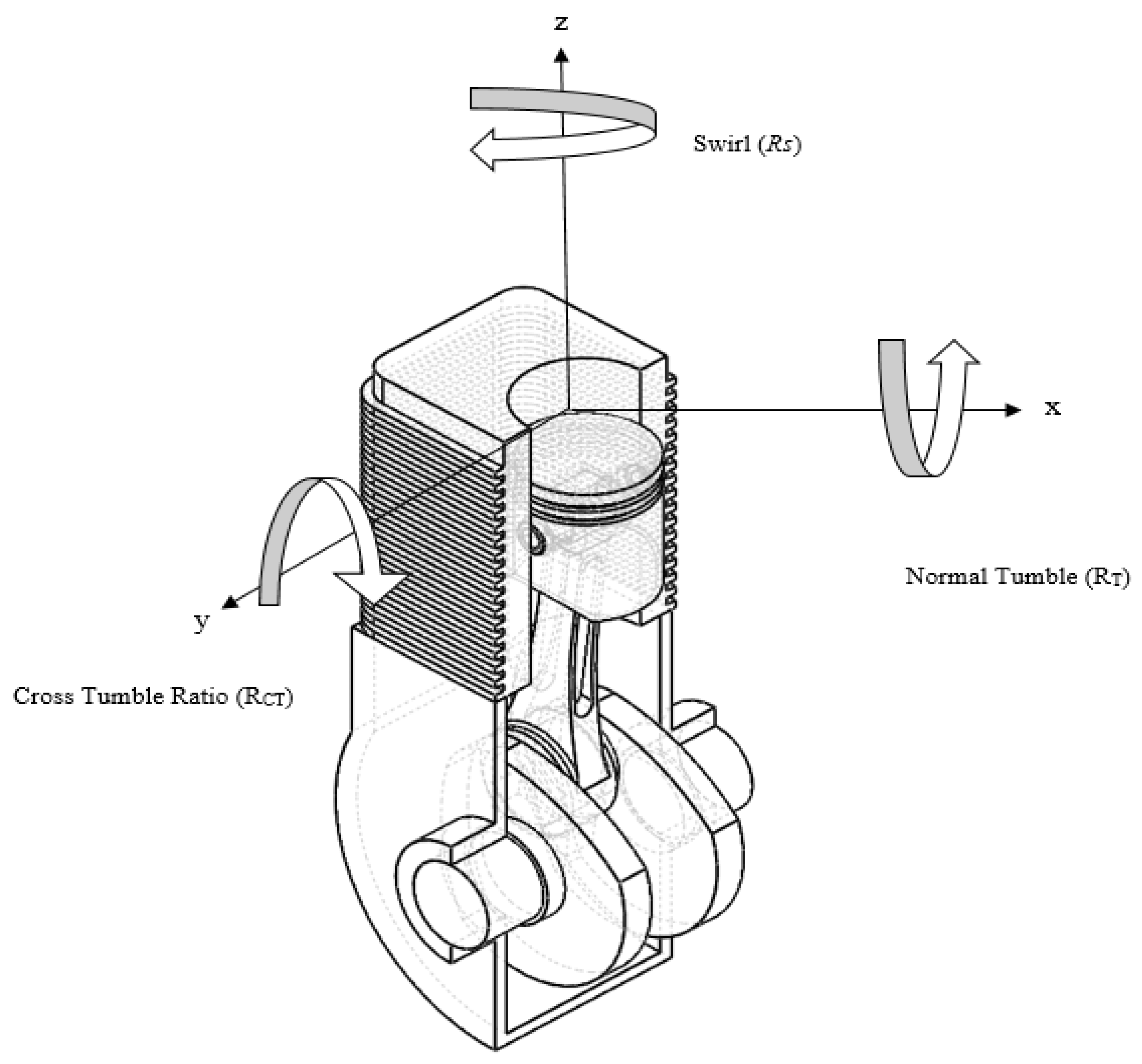
In order to maximize biofuel combustion, it is required that the biofuel is injected at higher pressure with in-cylinder airflow characterized by the swirl ratio (Rs), tumble ratio (R
T), turbulence kinetic energy (TKE) and cross tumble ratio (R
CT) to promote the evaporation, diffusion and mixing processes [
18]. Adjustment of the injection pressure and time will also allow the biofuel to be injected at the most intense air temperature in the cylinder and provide more time to evaporate [
17]. Having a sufficient period available for evaporation will improve biofuel diffusion, mixing and atomization at a finer size, thereby improving the quality of combustion [
19]. Meanwhile, the EB blending technique can improve the quality of biofuel by mixing it with water and the addition of emulsifier [
20]. The viscosity of biofuel can be reduced by preheating it to higher temperatures so that the biofuel can diffuse, thus, it is more likely to evaporate and mix efficiently when sprayed into a cylinder [
21,
22].
Theoretically, improving the in-cylinder air flow characteristics, as well as the swirl, tumble, and cross tumble ratio, will significantly affect the enhancement in vaporization, diffusion, and air-fuel mixing, particularly in the application of low grade or higher viscosity fuel, e.g., emulsified biofuel application in IC engines. The engine airflow from the intake manifold must be guided via guide vane design (GVD), before being induced into the cylinder. GVD is a static vane device that functions to divert airflow according to its designed shape. Normally, GVD is installed in between the air filter end and the entrance of the intake valve inside an intake manifold. Its simple design, requirement for minor modification, and the promising improvement in the in-cylinder air flow characteristics, make GVD superior to other airflow diversion methods. Bari et al. [
23,
24] reported that after considering the guide vane design in IC engines, lower specific fuel consumption (SFC) with an almost 12% reduction, as well as a drastic drop in soot emission were observed. They concluded that the guide vane is capable of improving the air turbulence, which increasing the flame propagation speed for better combustion.
The characteristic of the in-cylinder airflow is one of the most critical parameters for improving engine fuel combustion and performance [
24]. Few researchers have studied how to improve the in-cylinder airflow characteristics of a CI engine, such as by modifying the intake system and redesigning the piston-bowl. In this particular work, the improvement in the characteristics of the in-cylinder airflow was examined by studying the effect of three different GVD incorporated at the intake manifold with the use of a shallow depth re-entrance combustion chamber (SCC) piston in the engine. The improvement in the characteristics of the in-cylinder airflow were assessed in terms of Rs, R
T and R
CT and TKE contributing to an easy break down of the heavy molecular chains of EB during injection, and thereby improving the mixing of air and fuel in the combustion chamber. The application of GVD and the SCC piston-bowl in CI engines fueled by EB was shown to be the cheapest and simplest technique compared to other techniques.
The effect of GVD on the engine performance is based on four main parameters: the angle of the vane, height, length and number [
23,
24]. These parameters must be characterized to determine the optimum GVD condition to obtain the best in-cylinder airflow characteristics. Therefore, this work focused on the optimization of the vanes’ height by varying it across three models, namely, 0.20R, 0.40R, and 0.60R, that is, 0.2, 0.4, and 0.6 times the radius of the intake runner (R). Detailed information on the design, manufacture and testing of the guide vanes is given in the following sections.
2. Computer Simulation Construction
The guide vanes and SCC pistons model were initially designed to be implemented in a simulation. The process can be split into four main parts: develop the SCC piston-bowl, develop guide vane designs, develop the base model and construct the computational fluid dynamics (CFD) simulation. SolidWorks 2017 (Dassault Systemes SolidWorks Corporation, Waltham, MA, USA), a computer-aided software for drawing, was used to model the guide vanes and piston bowls while the developed base model was simulated using CFD software, ANSYS Fluent (Version 15.0, ANSYS, Inc., Canonsburg, PA, USA). The details of constructing the computer simulation model are outlined in the following sections.
In this work, the CFD simulation setting was set using the ANSYS Inc published IC engine setting [
25]. The fluid dynamics equations used to build the simulation include the momentum equation, the continuity equation and the energy equation.
The continuity equation can be written as:
where
U is the three-dimensional flow velocities in the x, y, and z directions, and
is the fluid density. Meanwhile, the momentum equation is based on Newton’s second law, where the surface force on the control volume and the body forces can be written as:
where
,
and
are the fluid density, strain rate, and momentum source, respectively.
The energy equation describes the rate of change of energy inside the fluid element. This is also known as the Navier-Stokes equation. The energy equation can be written as:
where
and
represent the total enthalpy and thermal conductivity, respectively.
In this simulation study, the shear stress transport (SST) turbulence model was implemented. The SST model is an eddy viscosity model comprised of a k-ɛ model outside of the boundary layer combined with a k-ω model in the inner boundary layer. In regions of adverse pressure gradient, the model includes a shear stress limitation with an initial turbulence intensity of 5%, which is sufficient for fully developed turbulence flow. The initial temperature and pressure were set at 300 k and 1 atm, respectively. The ANSYS FLUENT-Solver Theory Guide can be referred to for detailed theories and limitations of the model.
Based on the physical boundary condition of the engine, the simulation was divided into two analyses. The analysis of the intake required a direct connection from the intake runner and intake port to the clearance volume, which was controlled by the intake valve to draw in air during the downward movement of the piston in the y-direction. The insignificant components in this analysis were neglected since they did not contribute to the simulation results.
2.1. Engine Model
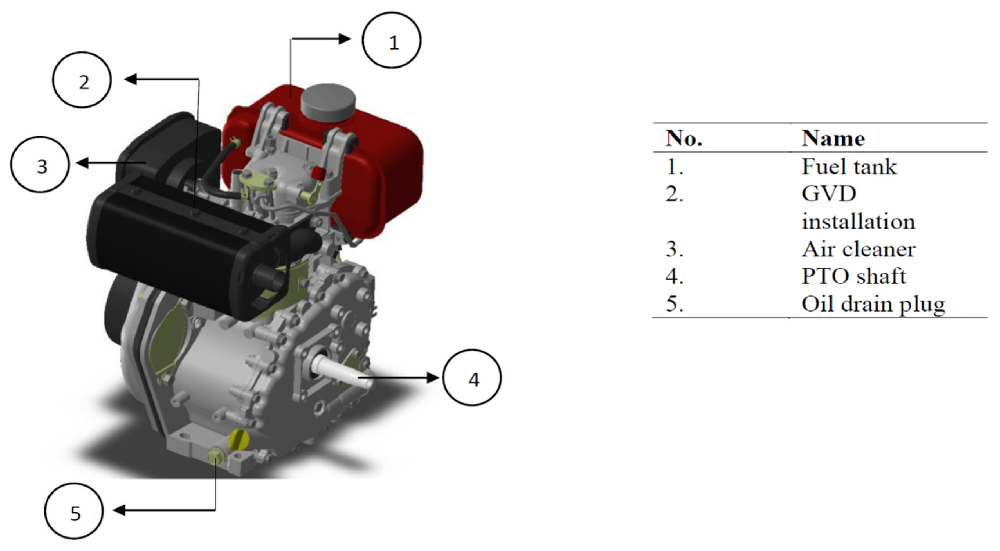
The engine model geometry was adapted from the engine used in the experimental studies of this work, i.e., the CI generator diesel engine model YANMAR L70AE installed with a four-stroke vertical single cylinder, one intake valve, and one exhaust valve, as shown in
Figure 1. It is a naturally aspirated, direct injection automotive engine. The experiments took place in the automotive laboratory of the School of Mechanical Engineering, Universiti Sains Malaysia using a constant engine speed of 2000 rpm.
2.2. Experimental Setup
A dynamometer controller (Focus Applied Technologies, model DC2AP) was coupled with the four-stroke, single cylinder CI generator diesel engine model YANMAR L70AE to supply load to the engine. The controller receives speed and loads the cell signal as the input signal, then manipulates current to the dynamometer in order to apply the required torque. An inductive speed sensor monitors the changes in the magnetic flux from a gear mounted to the dynamometer shaft. The teeth of the gear provide changes in magnetic flux and produce a sinusoidal wave signal, with 5 kW minimum load cell resolution, 400 V 3-phase load voltage, and 50 Hz AC supply.
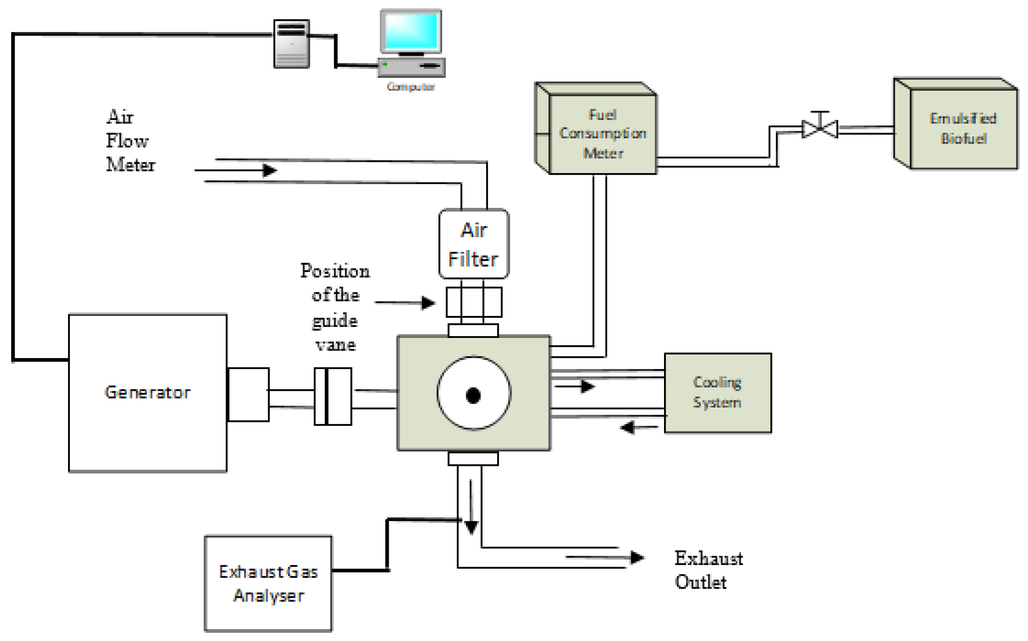
Figure 2 shows the schematic diagram of the complete engine setup with various instruments coupling. A K-type thermocouple with an accuracy of ±0.05% and a digital thermometer (brand flux 54 series II) capable of measuring temperature in the range of −200 °C to 1372 °C, were used to measure the exhaust gas temperature. Meanwhile, the ambient pressure was measured using a mercury J-tube barometer with a resolution of 1 mm/Hg (0.133 kPa) that was hung on the wall adjacent to the engine setup.
Table 1 shows the full technical specifications of the YANMAR L70AE CI generator diesel engine, which consists of the components used in the simulation model and applied to h the real engine used in this research. As can be seen in
Table 1, the engine was equipped with a single cylinder. The capacity or displacement of the YANMAR L70AE CI engine was calculated based on its bore (diameter of cylinder) and stroke (the travel distance of the piston from the top dead center (TDC) to the bottom dead center (BDC) values. In the simulation setup, five important components, the intake valve, exhaust valve, intake runner, exhaust runner, and cylinder were designed via the SolidWorks 2017 software and exported to the ANSYS Fluent software for in-cylinder air flow analysis. In the CFD solver, the intake valve and exhaust valve were both set as the solid domain, while the rest were set as the fluid domain to compute fluid flow.
2.3. Piston-Bowl Design Geometry
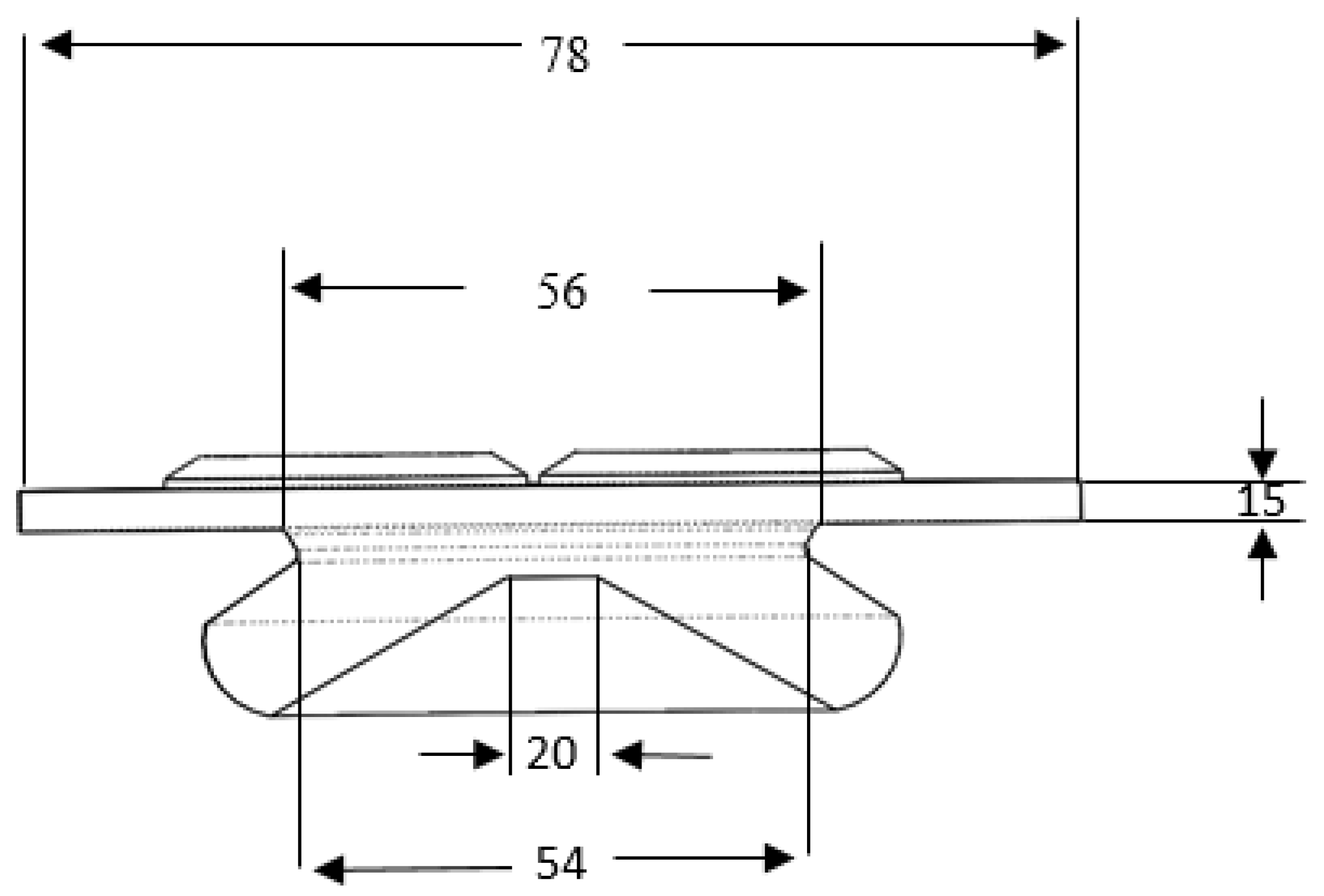
The selection of the piston-bowl design geometry is extremely critical due to the very close relationship between the air-fuel mixture and the formation of emissions in a diesel engine. The piston-bowl design geometry considered in this research was the shallow-depth re-entrance combustion chamber (SCC), owing to its ability to generate higher Rs, R
T, TKE, and R
CT [
23]. Moreover, the SCC piston-bowl design is capable of producing homogenous and well-organized airflow, which is applicable for high-viscosity fuels such as emulsified biofuels. In fact, the geometry of the SCC piston-bowl design, as illustrated in
Figure 3, provides better mixing of molecules with wider oxygen contact and higher temperatures during the compression stage.
2.4. Guide Vane Design
The purpose of GVD installation in the intake runner of an engine is to guide air flow before it is induced into the cylinder. The GVD is made up of a number of fixed blades that function to deflect in-cylinder airflow based on its shape. In general, GVD is mounted within the intake manifold system, i.e., in between the cleaner air filter end and the intake valve entrance. Sun et al. [
26] investigated “swirler” guide vanes mounted on the inlet valve seat before inducing air into the engine cylinder. Four types of swirler design were developed by applying different configurations of straight and arc designs. The swirler was tested in a direct injection diesel engine. By using the swirler in the intake valve, the fuel consumption was improved due to a 11.9% reduction in specific fuel consumption (SFC), as compared to the existing diesel engine with no swirler. Hence, GVD is considered as having the simplest design with no major modification of the intake manifold being required.
SolidWorks 2017 software was used to draw the guide vane model. So far, there has been limited research on the effect of guide vane parameters for instant vane height, length, angle, and number. The effect of guide vane height was studied and varied in this work (as shown in
Table 2). The vane height can vary from the minimum height up to the entire diameter of the intake runner, according to the literature findings [
27]. The vane’s minimum height could have a minimal effect on the rotational in-cylinder airflow, while excess maximization of the height of the intake runner would create an obstacle (in-cylinder airflow resistance) to the intake manifold, hence generating a volumetric efficiency effect [
28,
29,
30,
31].
Thus, it was decided to study the effect of a vane height in between the minimum and the maximum range of permissible vane heights. To avoid the volumetric efficiency effect, the vane height parameter was studied in a range from 0.20R, 0.40R and 0.60R in this work.
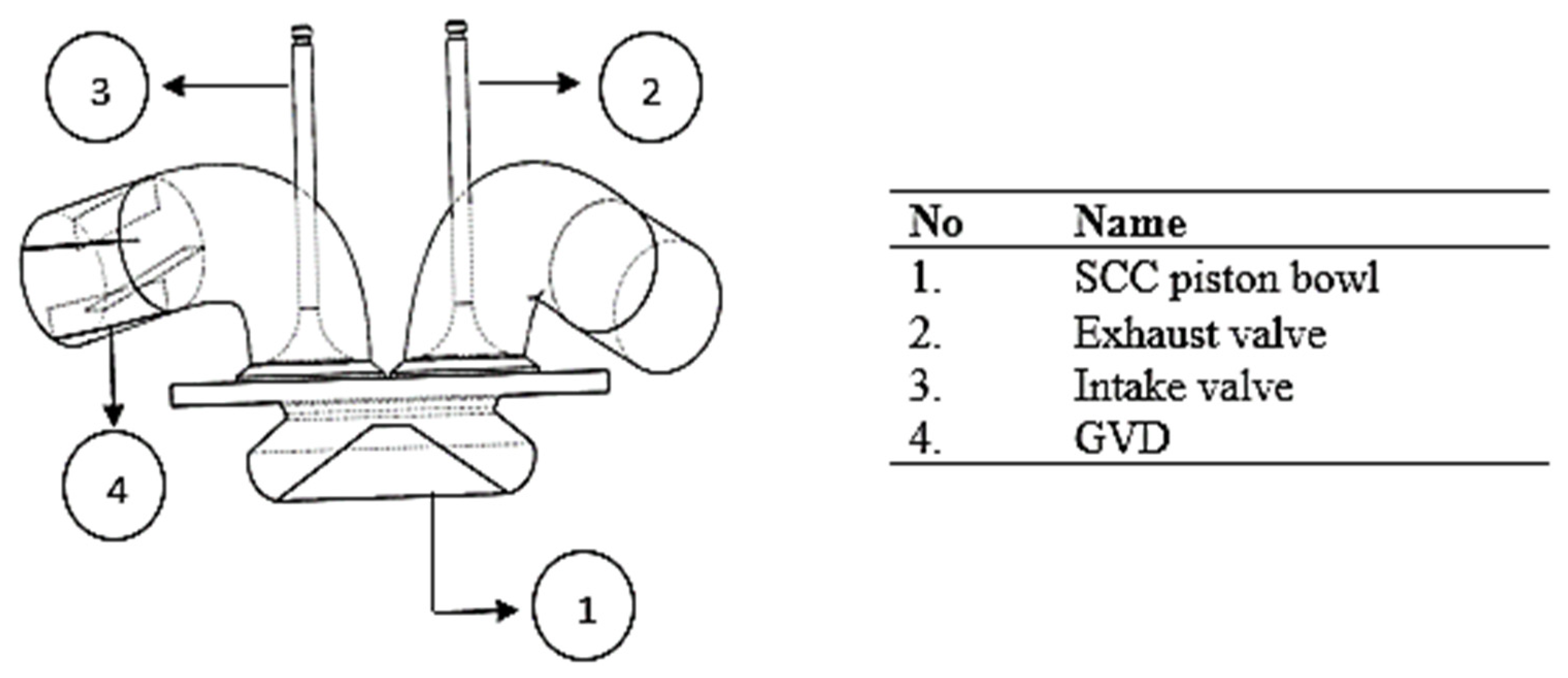
Figure 4 illustrates the base model and location of the GVD installation at the intake manifold before inducing to the cylinder. The designed model consists of four components: the SCC piston-bowl, exhaust valve, intake valve, and GVD. In the CFD solver settings, both intake valve and exhaust valve were set as the solid domain, while the other components were set as the fluid domain to compute the fluid flow.
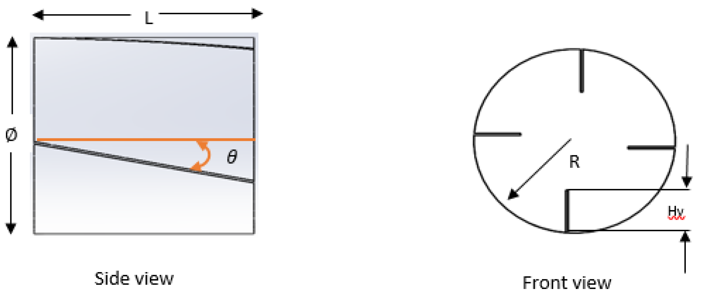
Figure 5 illustrates the design specifications of GVD. Several factors were considered in the design of GVD. From the literature, it was proven that larger surface area vanes yield greater swirl [
32,
33,
34,
35]. Since vanes function to guide the in-cylinder air flow, this consequently generates higher turbulence and creates sufficient momentum to sustain the swirl up to the end of the expansion stroke. However, vanes with excessively large surface area will become an obstacle to the in-cylinder airflow, thus reduce the volumetric efficiency. By compromising this factor, the height of GVD was varied at three different levels.
Table 2 presents the specifications of the GVD installed in the YANMAR L70AE CI generator diesel engine. This project utilized GVD with four vanes arranged 90
to each other, installed at 35
twist angle inside the intake manifold. The GVD vane height was varied at three levels, while the other parameters were retained at specific values as shown in
Table 2.
2.5. In-Cylinder Airflow Pattern Characteristics
Figure 6 schematically illustrates the characteristics of the in-cylinder airflow pattern of air-fuel mixing during the intake and compression stroke stages. The three main components influencing the in-cylinder air flow motion are Rs, R
T, and R
CT, which are calculated on the basis of the stroke of the motor crank angle. There are several reasons for inducing Rs, R
T, and R
CT. The high-level air turbulence at ignition produces advanced flame speed and more reliable combustion at very low air-fuel ratios. This is one of the purposes of increasing the in-cylinder air flow characteristics when operating engines with alternative fuels.
3. Numerical Result and Discussion
The simulation results of CFD using ANSYS Fluent Version 15.0 for all three types of guide vanes (0.20R, 0.40R, and 0.60R) compared with the base model (model with no vanes) are discussed in this section. The simulation results were also compared to similar research studies in the literature for validation purposes and reliability. Furthermore, the results of the simulation were also experimentally verified for numerical validation.
In theory, variable in-cylinder airflow has been known to contribute greatly to improving the in-cylinder airflow by stimulating improvement in the evaporation, diffusion and mixing during EB injection and the in-cylinder airflow. The measurable variables that determine the improvement are in-cylinder TKE, R
S, R
T and R
CT. In-cylinder TKE, which is defined as the in-cylinder airflow kinetic energy [
36], is capable of breaking down the heavier molecules and higher viscosity [
37] of the EB during spraying. In-cylinder turbulence airflow tends to accelerate the mixing and improves the process. Thus, this work focused most on the regional fuel injection, which is comprised of the crank angles, the start of injection (SOI) to the expansion, the process of combustion and period of mixing, which controls combustion. These are the critical stages in the process of combustion and significantly impact on further stages. The detailed results and discussion are presented in the following sections.
3.1. Numerical Validation
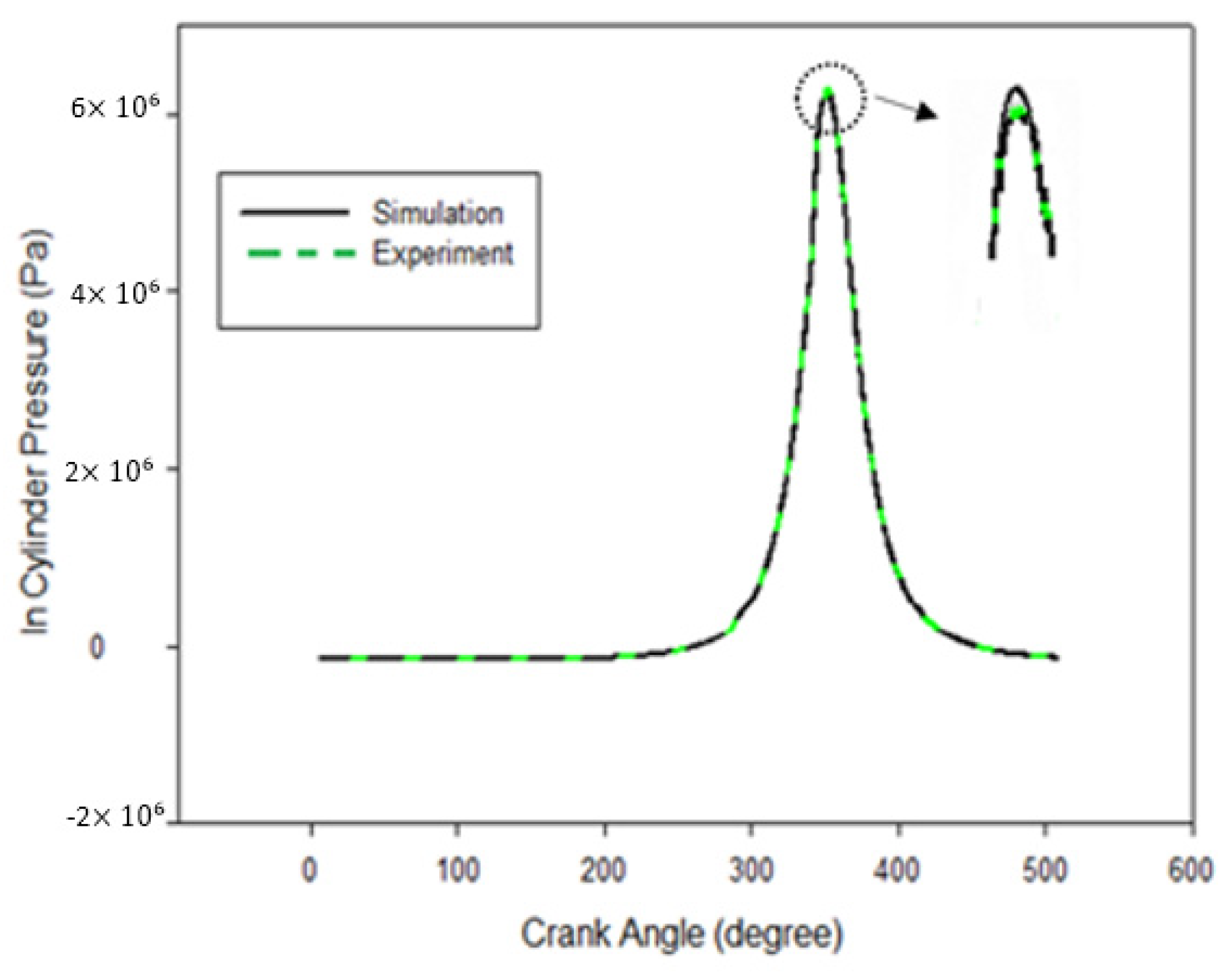
Figure 7 illustrates in-cylinder pressure against the crank angle (θ) without combustion running on a CI generator diesel engine YANMAR L70AE where the speed of rotation is 2000 rpm compared to the simulation data. To collect the experimental data from the experimental setup, a water-cooled piezoelectric pressure sensor (Kistler 7061B type) was installed near the valve to measure the cylinder pressure without combustion. The electrical charge output was converted to DC voltage from the piezoelectric pressure sensor using a charge amplifier (Kistler 5007 type). The data from the outflow charge amplifier, shaft encoder, and position sensor top dead center (TDC) were monitored via computer software Lab View (Version 7.1, NI, N Mopac Expwy, TX, Austin). To measure the boundary temperatures, a K-type thermocouple was used and placed close to the cylinder head for actual and a more accurate measurement. The graph in
Figure 7 shows that there was a slight difference of approximately 7% between the numerical and experimental results for the in-cylinder pressure. It should be noted that the numerical result did not consider friction loss and gas leakage in the cylinder towards the crankcase. Thus, numerical stimulation normally shows higher cylinder pressure compared to the experimental measurements.
3.2. Grid Independence Test (GIT)
The grid independence test, otherwise referred to as the mesh convergence study refers to grid or mesh independence on the solution’s accuracy. The computational calculation domain covers the valves and the inlet port, the cylinder head and the piston-bowl. The test must be carried out as it will affect the calculation time and cost. The cell size typically ranges from coarse to ultra, and the number of elements was set between 100–400 k, where about half of the cells were used to generate grid sensitivity and reasonable computation time on the cylinder head and piston-bowl. In this mesh generation, hexahedral mesh was adopted due to its better precision and stability compared to the tetrahedral mesh.
Table 3 shows a summary of the results and it was found that Case 3 showed a suitable meshing grid because of its less nominal deviation. Case 3 shows the optimum number of mesh; if the number of mesh elements is increased, the pressure shows a similar value with Case 3.
3.3. Turbulence Kinetic Energy In-Cylinder
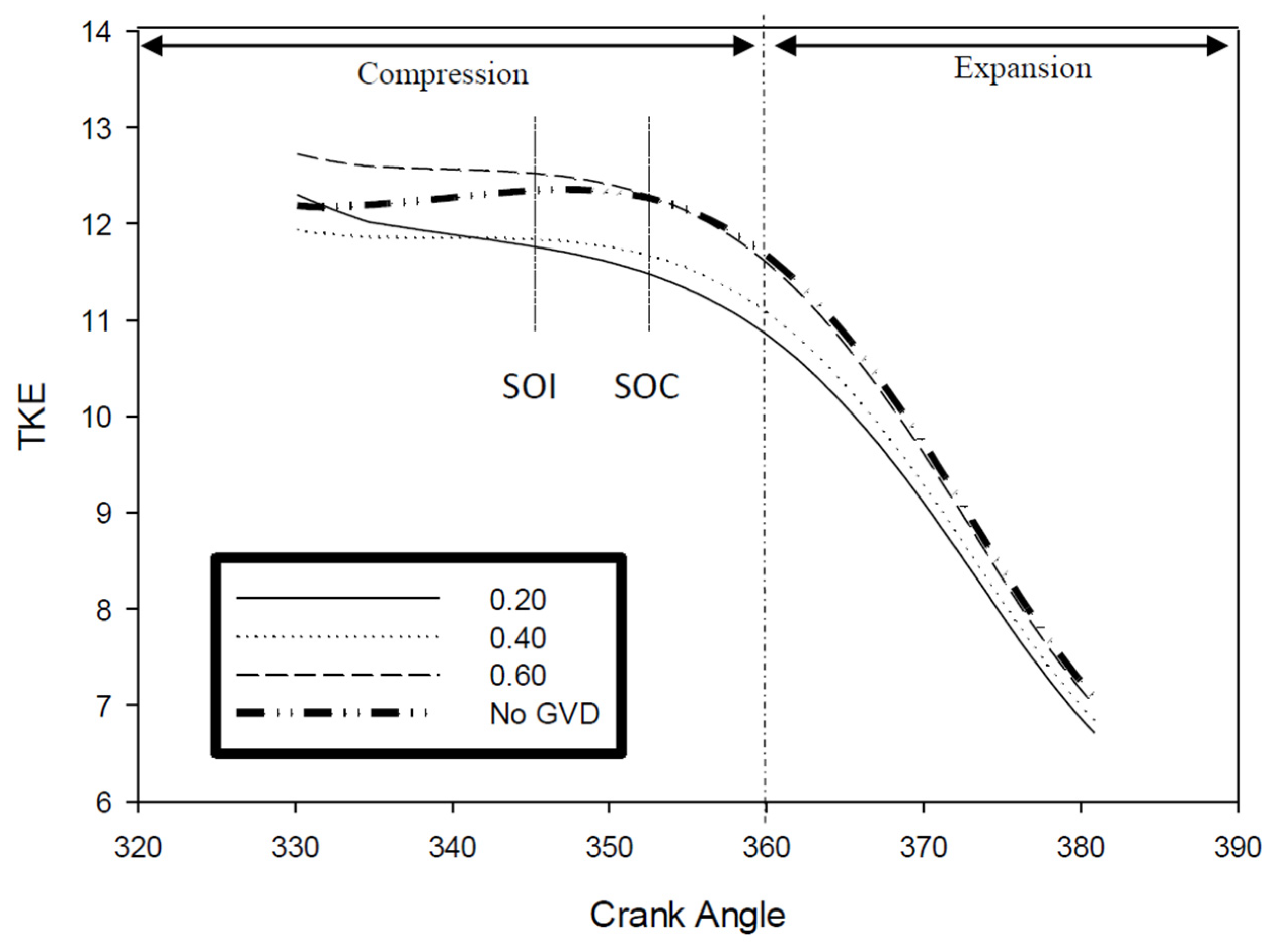
TKE forms the fundamental basis for turbulence and is turbulence-related intensity. It is a measure of the speed and the ability to aid the atomization of molecules during spraying. The spraying pattern of the emulsified biofuel and conventional diesel is dissimilar in terms of length and cone angle. The spraying pattern of conventional diesel shows a wider cone angle and shorter penetration length. However, for the EB, the behavior is vice versa with a smaller cone angle and higher length of penetration. In order to carry out a smoother and more efficient combustion using EB, the TKE value needs to be higher. Higher values of TKE imply a strong lateral flow that aids the flame propagation, reduces carbon deposited due to their ability to break down the molecules during injection, and promotes mixing with a wider area in combustion chamber. As shown in
Figure 8, the TKE values can be significantly improved by using the 0.60R GVD model compared to the model without GVD at the start of injection (SOI) at 346° and start of combustion (SOC) at 352°. Thus, GVD with a design of 0.60R displays good results compared to the other designs: 0.20R and 0.40R.
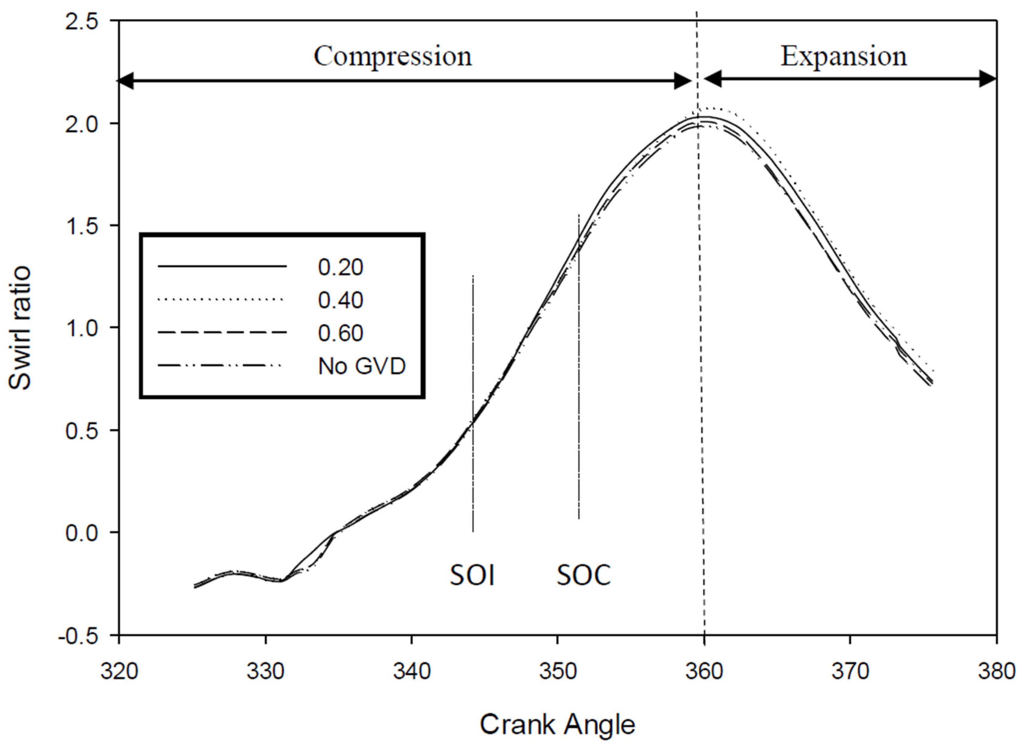
3.4. Swirl. Tumble and Cross Tumble Ratio (RS, RT, and RCT).
Rs needs to be maintained at a particular level for mixture preparation in diesel engines. In theory, it determines the speed of rotational flow of the local fluid around the cylinder axis.
Figure 9 shows the result of the in-cylinder swirl ratio against the crank angle (
θ). Three dissimilar models of GVD and one model without GVD were installed and tested in the engine. The higher values of Rs promote better, more homogeneous mixing of air/fuel and improve combustion. This is because the
Rs is determined by a strong airflow pattern. High Rs will improve and enhance the mixing specifically for low-grade fuels. The ratio values, as shown in the graph, can either be positive or negative. However, the concern is the magnitude of the ratio. Based on the graph, the 0.60R GVD produced the highest
Rs at the position of SOI at 346 °C, and was approximately 12% higher compared to the engine with no GVD. The 0.20R and 0.40R also improved the
Rs by approximately 4% and 5%, respectively, compared to no GVD. These results indicate that by installing GVD at the intake, the magnitude of
Rs was elevated gradually and this is also in good agreement with studies by Bari et al. [
23], which reported that the
Rs improved after modification of the guide vane swirl tumble device (GVSTD) in their experiment.
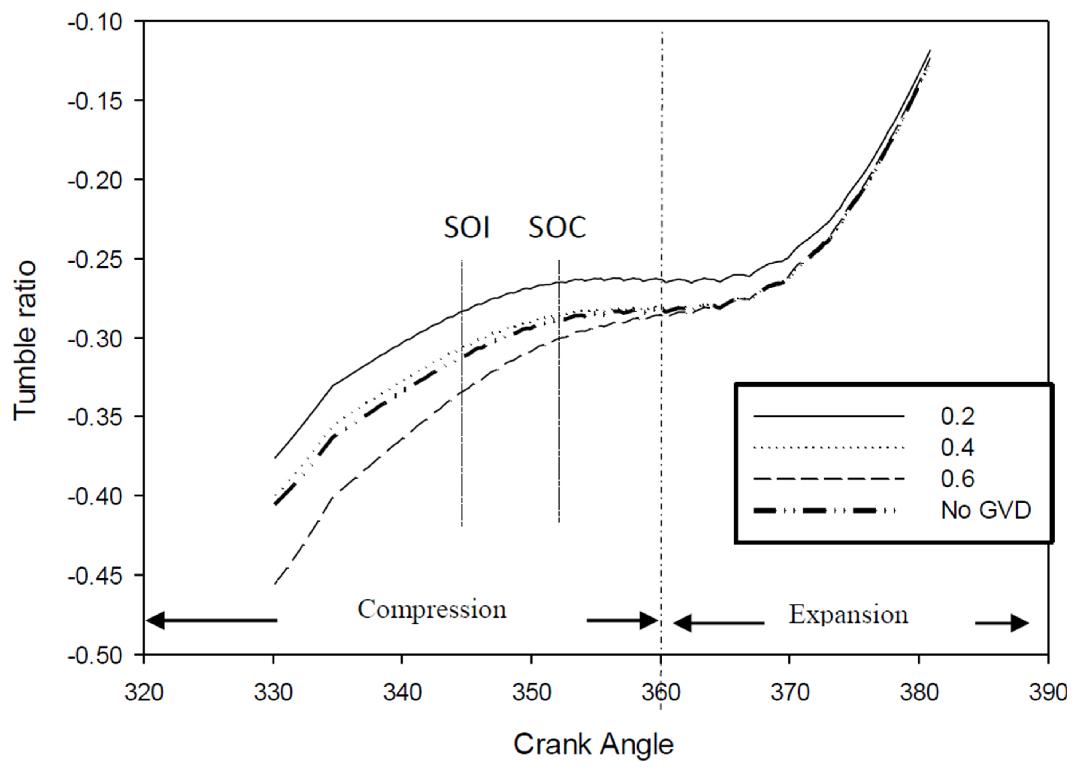
Figure 10 illustrates the behavior of R
T at different heights of GVD and crank angles before approaching TDC. R
T is defined as the ratio between the equivalent angular velocity of the instant solid body and the angular velocity of the engine [
31]. The negative and positive signs in the R
T values were neglected as they are arbitrary and only dependent on the magnitude obtained. The parameter of R
T contributes to the enhancement of flow turbulence and assists in homogenous air mixing along the piston-bowl. It can be seen from the graph that the 0.60R GVD type produced a remarkable R
T, which was approximately 40% higher compared to the engine without GVD, for both SOI and SOC. The other GVD designs demonstrated lower magnitudes of R
T compared to the baseline engine. This implies that the installation of GVD at the intake manifold generates a strong lateral airflow within the cylinder, which is imperative in enhancing the speed and spread of the fuel atomization during injection. As a result, it provides sufficient time for combustion due to the auto-ignition ability of the biofuel itself, thereby preventing carbon deposition. Therefore, the improvement of R
T within the cylinder when using emulsified biofuel will result in the spread of flames, decreased combustion duration, enhanced combustion efficiency, and improved fuel consumption.
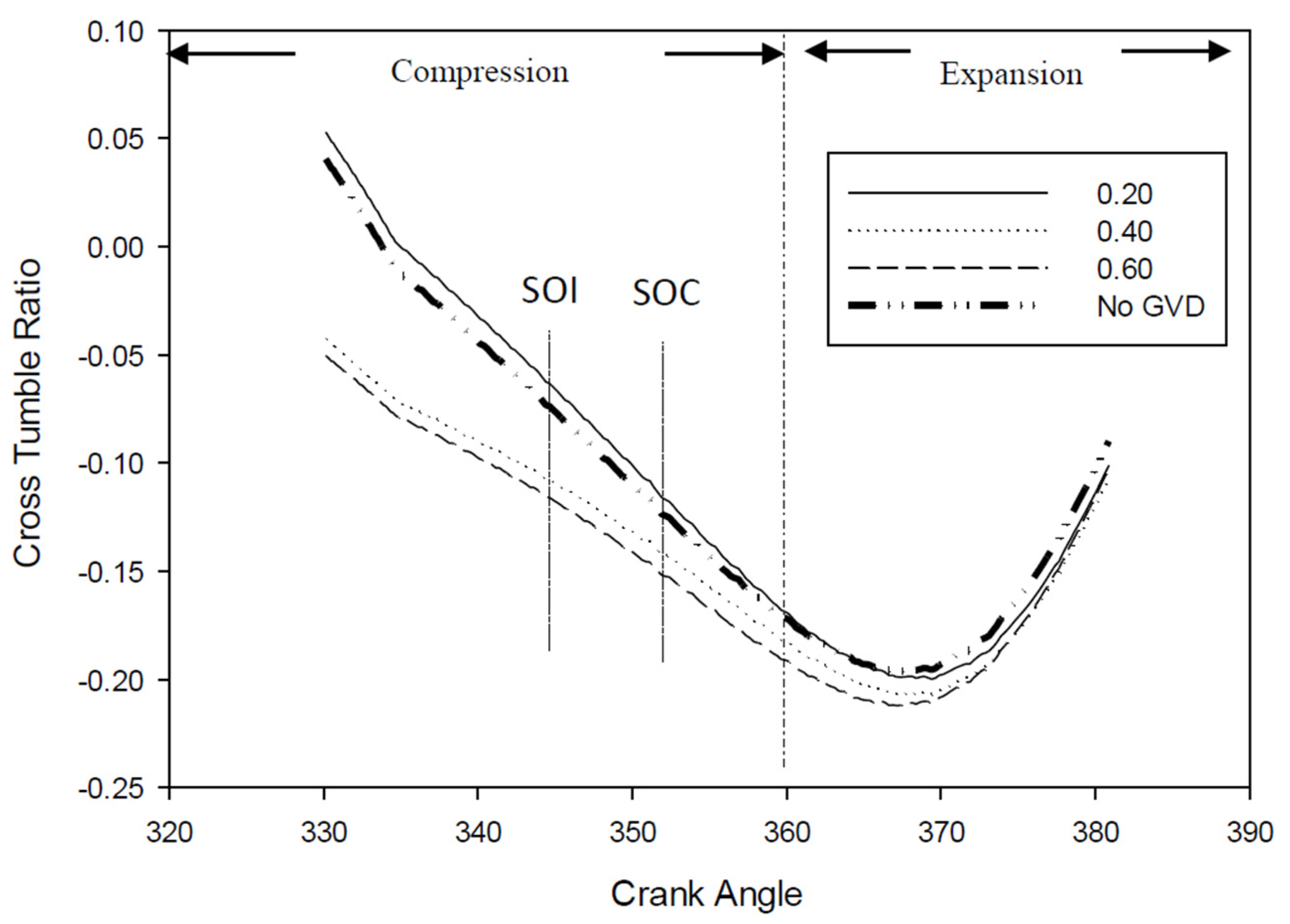
Figure 11 shows the behavior of R
CT at different heights of GVD and crank angles, before approaching TDC. R
CT is defined as the rotational ratio of airflow on the cross-model axes [
32,
33]. The effect of R
CT is similar to Rs and R
T, and it contributes to the enhancement of flow turbulence and assists in homogenous air mixing along the piston-bowl. A high R
CT was revealed in the application of GVD compared to the engine without GVD. In theory, the improvement of R
CT in combustion facilitates increased flow turbulence and aids the proper mixing of fuel and air along the piston-bowl into a homogeneous mixture. Wang et al. [
38] investigated and reported that enhancing R
CT air motion in the combustion chamber is important as it could increase the air-fuel mixing process, yield faster burning rates, increase the efficiency, and improve the air management. As previously mentioned, the use of higher viscosity fuels such as emulsified biofuels will degrade the atomization process, and thereafter, decrease the cone angle and increase the penetration length. Consequently, when the GVD is the correct height, R
CT could significantly reduce the penetration length, which is expected to widen the cone angle during injection.
Figure 11 shows that the 0.60R GVD exhibits the highest R
CT value relative to the baseline engine and other GVD models. It is notable that the 0.60R GVD could produce a homogeneous mixture during compression, which consequently improves the lateral air flow within the cylinder.
3.5. Intake Stroke Streamline Airflow Characteristics
Figure 12 illustrates the intake streamline stroke at a crank angle of 30°, 60° and 90° after TDC. The intake stroke installed with GVD has a significant effect, particularly in terms of improving air velocity compared to its behavior without GVD installation. Hence, the increase in vane height (H
v) during the intake stroke has a significant effect on the air velocity structure. This is because the air was initially guided via GVD to generate turbulence flow at the start of the intake airflow. The results for the intake airflow show that a swirl flow was formed at the beginning of the intake stroke while air is being drawn into the cylinder. Then, tumble flow was formed following the swirl flow from the intake of air motion at the valve. In order to enhance the turbulence intensity, the vortex flow needs to be increased [
39]. Nevertheless, the flow structure changes dramatically along the cylinder (due to change in geometry at the intake stroke) influenced by the engine geometry as reported by Hamid et al. [
40,
41]. Thus, as is clearly seen in
Figure 11, a progressive airflow was achieved and demonstrated via the installation of the 0.60R GVD design.
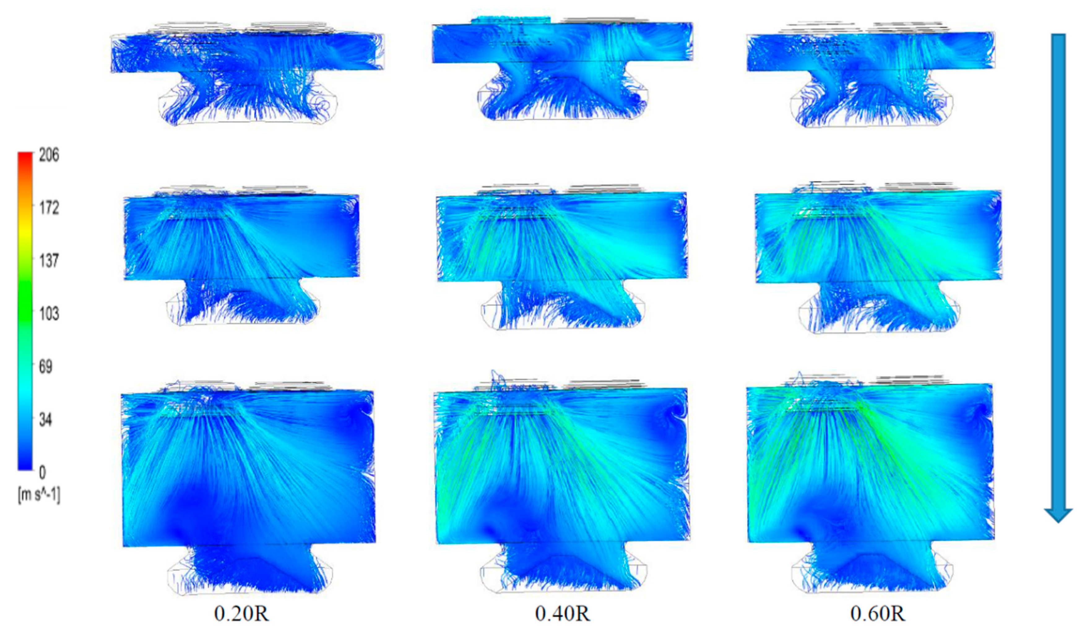
3.6. Compression Stroke Streamline Airflow Characteristics
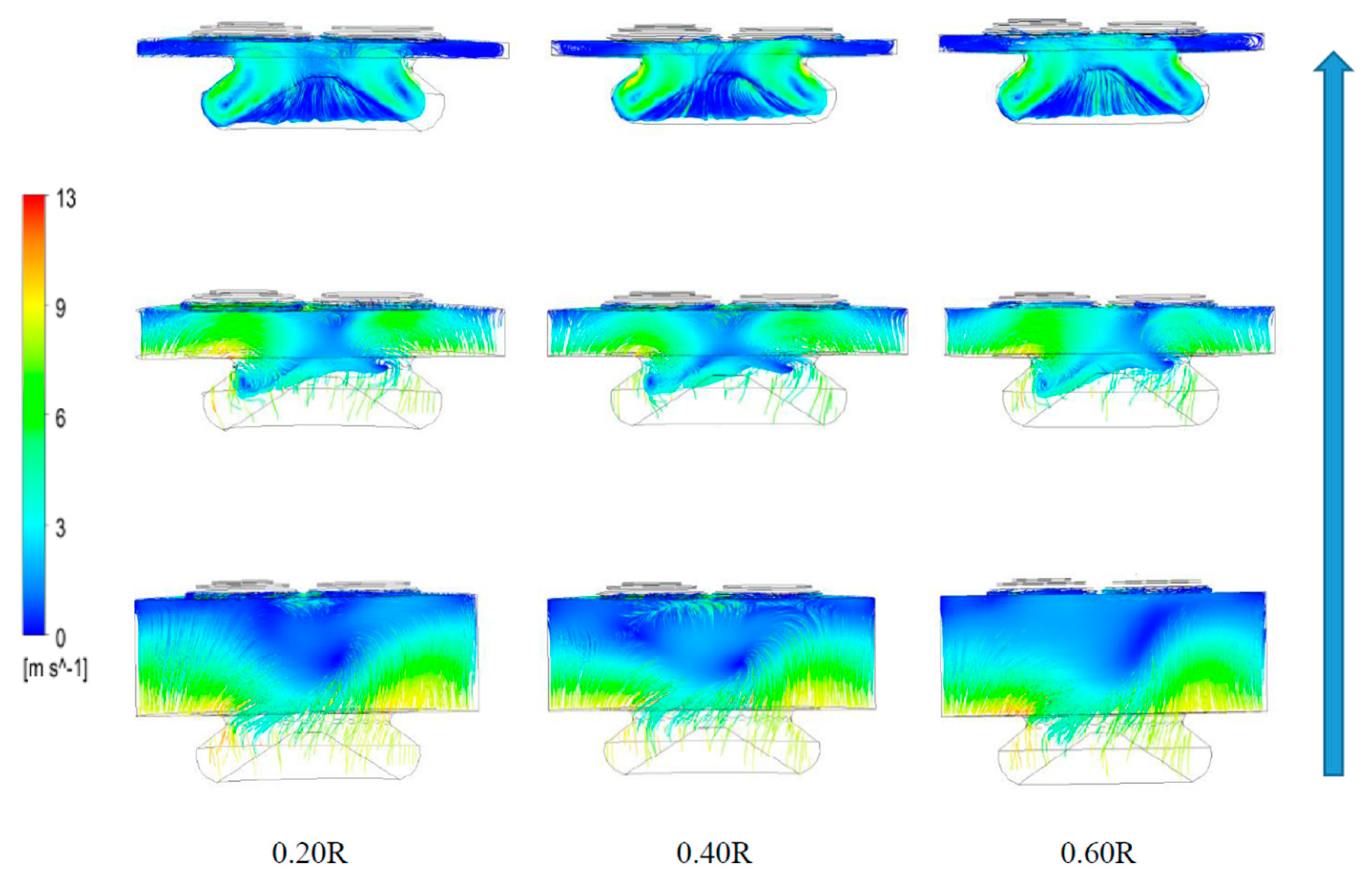
Figure 13 illustrates the instantaneous compression stroke streamline at the 310°, 330°, and 346° crank angles. The scaling change (due to compression) and the increasing pressure and density of air during the compression stroke have significantly affected the amplification of the turbulent flow and enhanced the velocity of air. In the duration of the piston approaching the TDC, the air characteristics show different profiles depending on the GVD’s and cylinder’s swept volume. Nevertheless, the 0.60R GVD design indicated that airflow was concentrated along the piston bowl and produced significant improvement in the air velocity, and exhibited homogenous turbulence airflow. The 0.60R GVD design also demonstrated that the air turbulences were concentrated in the piston-bowl and produced stronger airflow compared to that of the 0.40R GVD design. The 0.20R GVD produced the weakest air turbulence flow as compared to the other designs. The results showed strong evidence that the 0.60R GVD design incorporated with SCC piston is capable of producing strong turbulence flow that generates high air velocity. Furthermore, the model in
Figure 12 shows the ability of 0.6R GVD model to transport the heavier molecules of EB at uniform flow.
4. Conclusions
This work successfully examined the effects of installing GVD at the intake manifold and the modifications associated with the SCC piston, in order to improve the in-cylinder airflow characteristics for higher engine performance and reduce the harmful emissions of CI engines run with EB. A numerical method was used to explore the different design parameters of the guide vanes to achieve the above-mentioned objectives. The optimization of the guide vane design was carried out by studying the effect of vane height, while the length, number, and angle of the guide vanes were kept constant. The height of the vane was varied from no GVD condition, GVD 0.20, 0.40 and 0.60 times the intake runner radius, R, which were called 0.20R GVD, 0.40R GVD and 0.60R GVD. Of the different tested vane heights, the 0.60R GVD demonstrated about 4 to 5% improvement in efficiency based on the results of the TKE, Rs, RT, and RCT in-cylinder airflow characteristics, thus suggesting 0.60 as the optimum GVD height for incorporation into the SCC piston design. The study will be extended and further investigated using a strategic combination of GVD with the SCC piston. Besides, the effects of the injection profile, spray structure, and combustion characteristics when using higher viscosity fuels such as EB are worth exploring.

 ,
, 


