Article

Influence of Gasoline Addition on Biodiesel Combustion in a Compression-Ignition Engine with Constant Settings

Faculty of Mechanical Engineering and Computer Science, Czestochowa University of Technology, 42-201 Czestochowa, Poland
*
Author to whom correspondence should be addressed.
Processes 2020, 8(11), 1499; https://doi.org/10.3390/pr8111499
Submission received: 21 October 2020 / Revised: 9 November 2020 / Accepted: 17 November 2020 / Published: 19 November 2020
(This article belongs to the Special Issue Processes for Biofuel, Biogas and Resource Recovery from Biomass)

Abstract

:
This paper presents results of investigation of co-combustion process of biodiesel with gasoline, in form of mixture and using dual fuel technology. The main objective of this work was to show differences in both combustion systems of the engine powered by fuels of different reactivity. This paper presents parameters of the engine and the assessment of combustion stability. It turns out that combustion process of biodiesel was characterized by lower ignition delay compared to diesel fuel combustion. For 0.54 of gasoline energetic fraction, the ignition delay increased by 25% compared to the combustion of the pure biodiesel, but for dual fuel technology for 0.95 of gasoline fraction it was decreased by 85%. For dual fuel technology with the increase in gasoline fraction, the specific fuel consumption (SFC) was decreased for all analyzed fractions of gasoline. In the case of blend combustion, the SFC was increased in comparison to dual fuel technology. An analysis of spread of ignition delay and combustion duration was also presented. The study confirmed that it is possible to co-combust biodiesel with gasoline in a relatively high energetic fraction. For the blend, the ignition delay was up to 0.54 and for dual fuel it was near to 0.95.

1. Introduction

In recent years, research works have focused on the reduction of harmful substances emitted by internal combustion engines. Compression ignition engines are widely used in industry and transportation due to their higher fuel economy, durability and specific power output. On the other hand, these engines are the major sources of nitrogen oxides and particulate matter (PM) emissions [1,2,3]. Research works are aimed at creating a high performance engine with low exhaust gas emissions. It seems to be a good solution to use the compression ignition engine due to higher energy conversion efficiency, mainly due to a relatively high compression ratio, lean stratified charge and no throttling.
For many years, there has been an increased interest in the use of unconventional fuels for compressing piston engines [4,5]. In practice, there are two main ways of co-combustion of alternative fuel and diesel or biodiesel fuel. One way is to produce a blend of diesel fuel with other fuel and then bring the mixture to the engine, using a typical supply system for a diesel engine (Figure 1a). The greatest difficulties are phase separation and limiting miscible fuels. In the available literature, it can be find works on co-combustion of diesel fuel with gasoline. One of the important problems is to determine behavior of ignition during co-combustion of fuels of different reactivity. Nam et al. [6] investigated influences on auto ignition and combustion behaviors of various ambient temperatures from 600 to 800 K and different biodiesel fractions in blend with gasoline in a rapid compression expansion machine. They stated that with the increased biodiesel fraction in fuel blends, the ignition delay is shortened. It was stated that the reason for this is a better flammability of diesel fuel than gasoline. Another conclusion was that higher ambient temperature during injection decreases auto ignition delay of the gasoline/biodiesel blend. Putrasari et al. [7,8] conducted research on a gasoline compression ignition engine using a biodiesel additive to gasoline, compared to neat diesel fuel with single injection strategy. Authors stated that the higher biodiesel content in the fuel caused the higher cylinder pressure. The lower biodiesel fraction (5%) in the gasoline fuel resulted the lower thermal efficiency of engine. The next conclusion was that low-temperature (1800 K) combustion achieved for blend of 5% of diesel fuel with multiple injections. The heat release rates for multiple injections for burning of blend with 5% of diesel were lower than that for a single injection of 100% diesel [8]. The auto-ignition process and the ignition delay time were influenced by the quality of fuel fragmentation in the injection process. The researchers carried out experiments on the participation of gasoline fraction in a mixture with diesel fuel on the fuel jets. Das et al. [9] presented results of study on spray characteristics of neat gasoline and biodiesel addition (10%, 20% and 40% by volume) to gasoline in three different ratios under low load and different injection pressure conditions. They stated that an increase in injection pressure significantly accelerated the spray development process while penetration length increased with the increment of biodiesel fraction. The spray cone angle was increased for higher gasoline content which promotes a larger spray width. It is the higher density of biodiesel in comparison to gasoline that causes a smaller cone angle and higher penetration of the jet. A decrease in droplet size was observed according to breakup regimes under high injection pressure and low ambient density [9].
Studies on the co-combustion of biodiesel with gasoline were also carried out. Adams et al. [10] presented results of influence on combustion of biodiesel addition to gasoline in a compression ignition engine. Stable combustion was achieved for all three analyzed fuels. Up to 10% biodiesel content significantly reduced ignition delay and advanced the phasing of combustion compared to the reference fuel. The authors stated that the reduction of ignition delays resulted from the increased cetane number (CN) of the blended fuels leading to reduced intake temperature requirements [10].
The co-combustion of gasoline with diesel fuel in compression ignition engines can be provided by using the concept of a dual fuel engine. The dual fuel mode was usually used to burn alcohol fuels in compression ignition engines, like methanol, ethanol and others [11,12,13,14]. Park et al. [15] presented results of a comparative analysis of co-combustion of bioethanol and gasoline with biodiesel. The authors stated that dual fuel combustion was characterized by a higher peak pressure, shorter ignition delay, lower NOx and soot emission, but higher HC and CO emission compared to single-fuel combustion. In a comparison of bioethanol and gasoline during dual fuel combustion, biodiesel–bioethanol dual fuel combustion showed lower peak pressure, longer ignition delay, and higher indicated mean effective pressure (IMEP) than biodiesel–gasoline dual fuel combustion. The biodiesel–bioethanol dual fuel combustion mode showed higher HC emission than the biodiesel–gasoline dual fuel combustion mode, and the CO emission level was similar in both combustion modes.
The effect of gasoline fumigation on the energy and exergy balance of a compression ignition engine fueled with waste cooking oil biodiesel and diesel blend was also investigated. The results showed that gasoline fumigation increases the energy and exergy efficiency. The main conclusion was that the combination of biodiesel and gasoline fumigation might be used as a substitute for diesel fuel in diesel engines under high loads, with higher exergy efficiency and lower exhaust exergy losses [1].
A lot of works in order to determine the influence of gasoline/biodiesel fraction on the properties of the blend have been conducted. Changing the ratio of fuels in the mixture causes a change in the physical properties of the mixture. This has a significant impact on fuel injection and the combustion process.
The injection fuel flow rate into the cylinder for higher density and higher kinematic viscosity fuel resulted in a higher mass flow rate when the injector fully opens [16]. Other research shows that the viscosity change of the blended fuels cannot be assumed to be linear with respect to the biodiesel concentration in a mixture with gasoline. Adding biodiesel to gasoline fuel (20% of biodiesel) increases the cetane number of the fuel, allowing the blend to ignite more readily, even in the ambient intake air condition, compared to the 100% gasoline [8]. Higher biodiesel-blended fuels maintain a higher level of viscosity and surface tension, and as a result, gasoline–biodiesel blends get difficulty in a rapid breakup and disperse processes. Furthermore, higher biodiesel-blended fuel shows an increase in tip penetration that can be attributed to the increase in droplet size and spray momentum flux. Higher gasoline percentages exhibit larger spray angles. A decrease of biodiesel may lead to poor viscosity and surface tension, which contributes to breaking up the fuel droplet and strengthens the air entrainment under ambient conditions. The lower viscosity of gasoline decreases the overall viscosity of the blends and, consequently, the spray can easily dissipate [9].
In the present work, the authors have attempted to compare the results of the co-combustion process of biodiesel and gasoline using two modes—a blend and using dual fuel technology. The research concerned the analysis of the combustion process and the analysis of non-repeatability for set of subsequent engine operation cycles and emission. The analysis was made for heat release rate, combustion stages, combustion stability and emission of exhaust gases. Both combustion systems obtained on the same engine were compared with the same constant load and almost the same proportion of combustible fuels. The obtained results provide the opportunity to compare the effects of a dual fuel combustion system powered by biodiesel and gasoline. In the available literature, there are many works on the co-combustion of diesel or biodiesel with gasoline. However, it is more difficult to find a comparison of two combustion systems. Researchers use different engines which operate under different conditions and are controlled differently. In this paper, the authors used the same engine to explore the two different combustion systems. In addition, the authors used biodiesel instead of diesel, which is different from other works. It should be noted that the paper presents the results of the analysis for the engine with factory settings without any changes to the control system. It should be noted that no optimization of the injection start angle was carried out. The present work aims to fill the above knowledge gap.

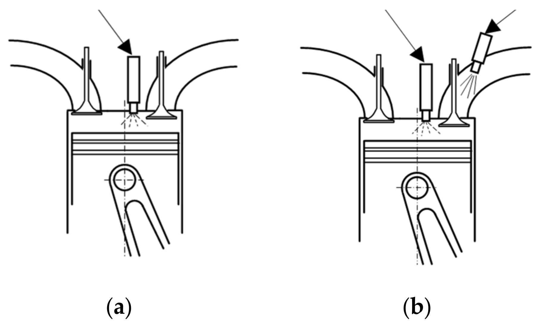
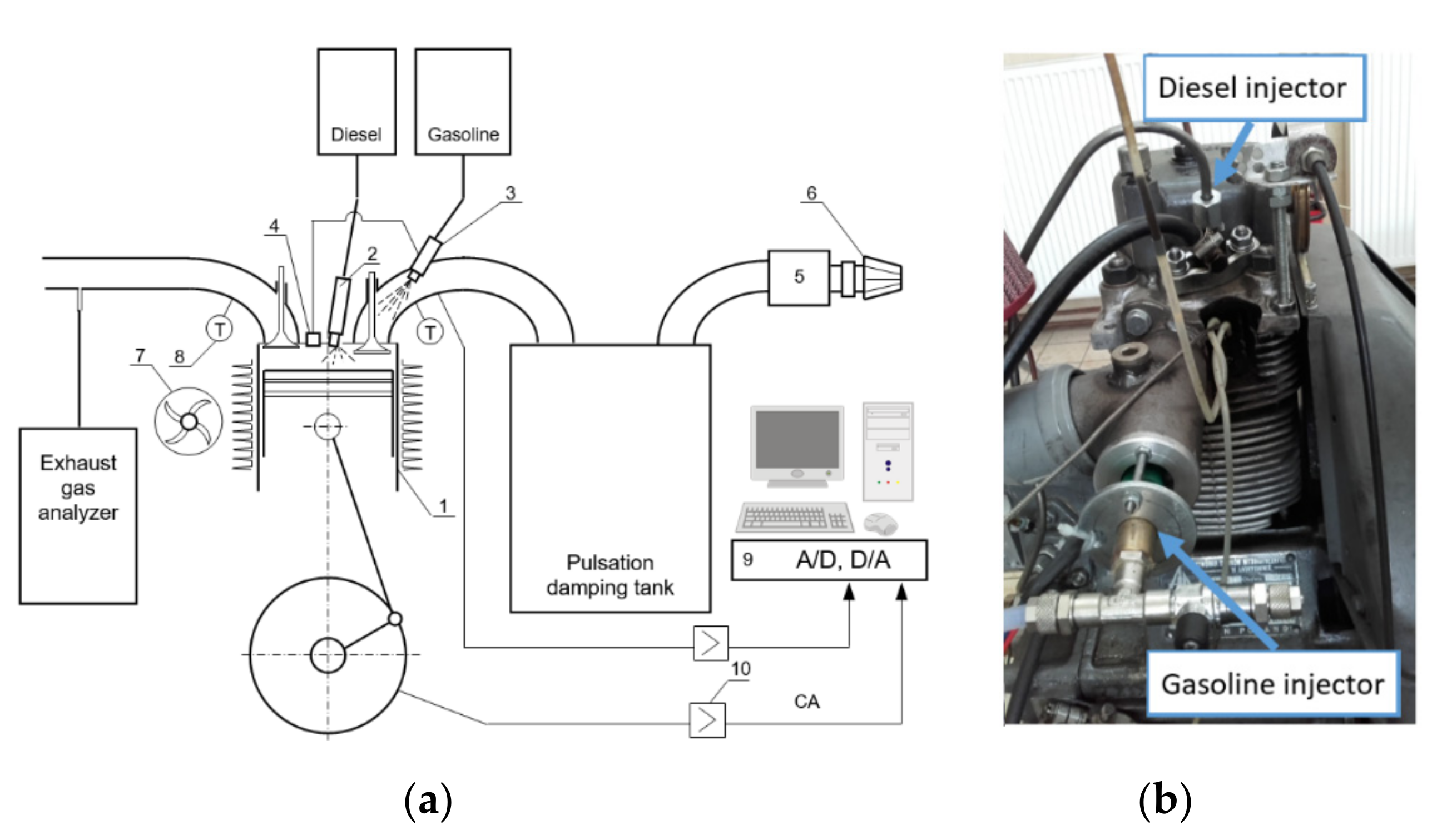
2. Experimental Setup

The tests are for a stationary engine operating under constant conditions and load used to supply power generators. The study was carried out on a compression ignition engine operated with constant rotational speed of 1500 rpm and constant torque. It was a one-cylinder air cooled, naturally aspirated, direct injection engine. This engine was adapted to work as a dual fuel engine by installing independent port fuel injection system. The port fuel injector was installed upstream of the intake manifold in such a way that fuel spray was delivered close to the intake valve. Gasoline was injected in the intake duct at 3 bar injection pressure and the value of the fuel dose was determined by the injector energizing time. The injection system was equipped with an electronic control system linked to the signal of the crankshaft position.
Test engine operated with constant angle of beginning of biodiesel fuel injection equal to 23 deg before the top dead center (TDC). The test bed is presented in Figure 2 The main engine parameters are presented in Table 1.
The schematic test bed setup is shown in Figure 2 and the engine specifications are listed in Table 1. A piezoelectric pressure sensor was installed in the cylinder head for measurement of the in-cylinder pressure. A crank angle encoder of 1 deg crank angle (CA) resolution was used to measure the crank angle position.
A typical measuring system for engine identification was used in the tests. It consisted of a pressure sensor Kistler 6061 SN 298,131 (sensitivity: ±0.5%) cooperated with charge amplifier Kistler 5011B (linearity of FS < ±0.05%). The pressure recorded with a of crank angle resolution of 1 deg using an acquisition module, Measurement Computing USB-1608HS—16 bits’ resolution, sampling frequency 20 kHz and using software for digital recording and analysis of the frequency signals [17]. Exhaust gas analysis used a Bosch BEA 350 analyzer for CO, HC, NOx, CO2, O2 and, for soot measurement, used an AVL Smoke Meter of a measurement range 0–10 filter smoke number (FSN), detection limit: 0.002 FSN or 0.02 mg/m3. Full details of the apparatus and description of the results processing procedure, error analysis is shown in other studies from the authors [18]. In the case of the combustion of fuel blends, we used volumetric fraction every 10%, and then converted fraction into energy shares, which are presented in Figure 3. In Table 2, the fuels’ properties are presented.
Diesel fuel and gasoline were standard, commercially available fuels, meeting the respective norms—EN 590 for diesel and EN 228 for gasoline. Biodiesel B100 is a biofuel produced from vegetable oils and meets the EN 14214 norm on the European Union markets.
For dual fuel mode, the fraction of biodiesel/gasoline fractions are presented in Figure 3. Theoretically, an increase in the share of gasoline was assumed every 10% of the energetic fraction, and after the completed measurement procedure, the recalculation of fuel shares was made. The exact energy share of gasoline can be read from the horizontal axis of Figure 3.
The lower heating value (LHV) of gasoline compared to the LHV of biodiesel is higher by 15%. Analyzing the data in Figure 4, it can be stated that with an increase in gasoline fraction in the case of dual fuel (DF), the fuel mass dose was decreased due to higher LHV of gasoline. In the case of blend combustion, the highest dose of fuel mass was noticed for higher gasoline energetic fraction due to deterioration of the combustion process. These data were determined based on hourly consumption of fuel with the assumption of a constant engine torque. With the largest fraction of gasoline, it was quite difficult to maintain a constant torque of the engines.

3. Results

This paper presents the results of an experimental investigation into the co-combustion process of gasoline with biodiesel as a blend or using dual fuel technology. The tests were carried out on the same engine under comparable conditions. Both combustion systems were implemented in the same engine and the same test system was used for the tests. The tests were carried out in a short period of time, where the ambient temperature, air humidity and fuels used were from the same supply. At each test point, the engine was fully warm up and its parameters were stabilized. The engine was run until the engine reached a constant temperature of exhaust gases and invariable emission. Biodiesel and gasoline are fuels of different reactivity and, due to this phenomenon, the combustion process occurred differently than in the case of reference fuel.

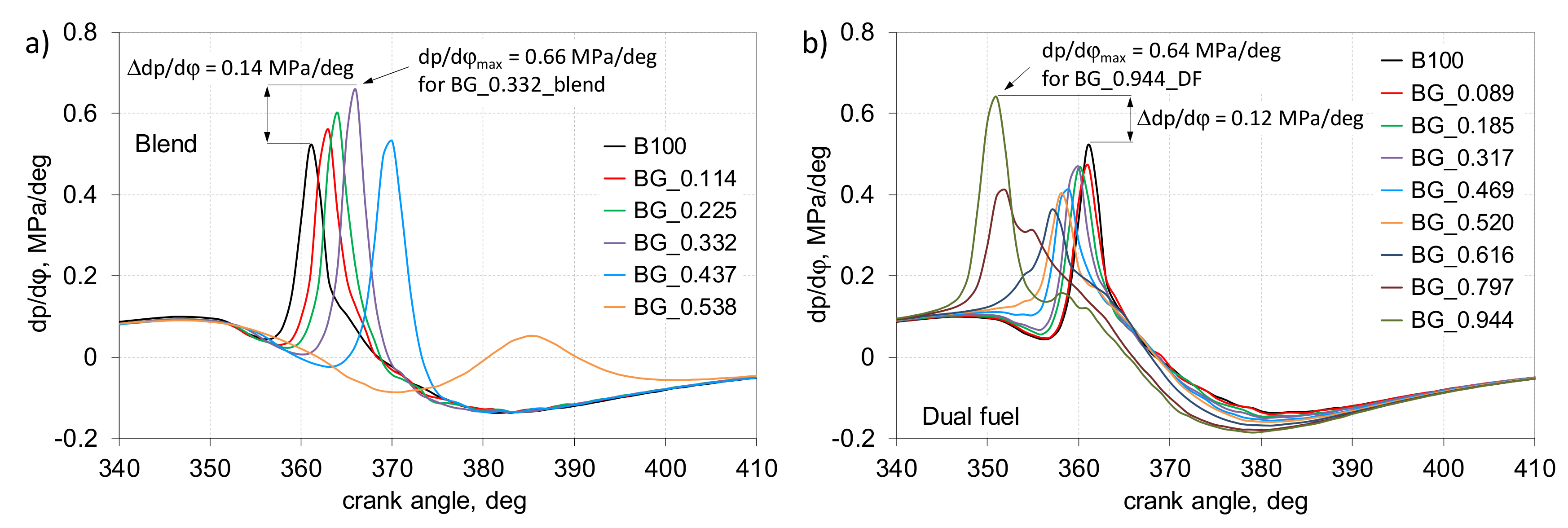
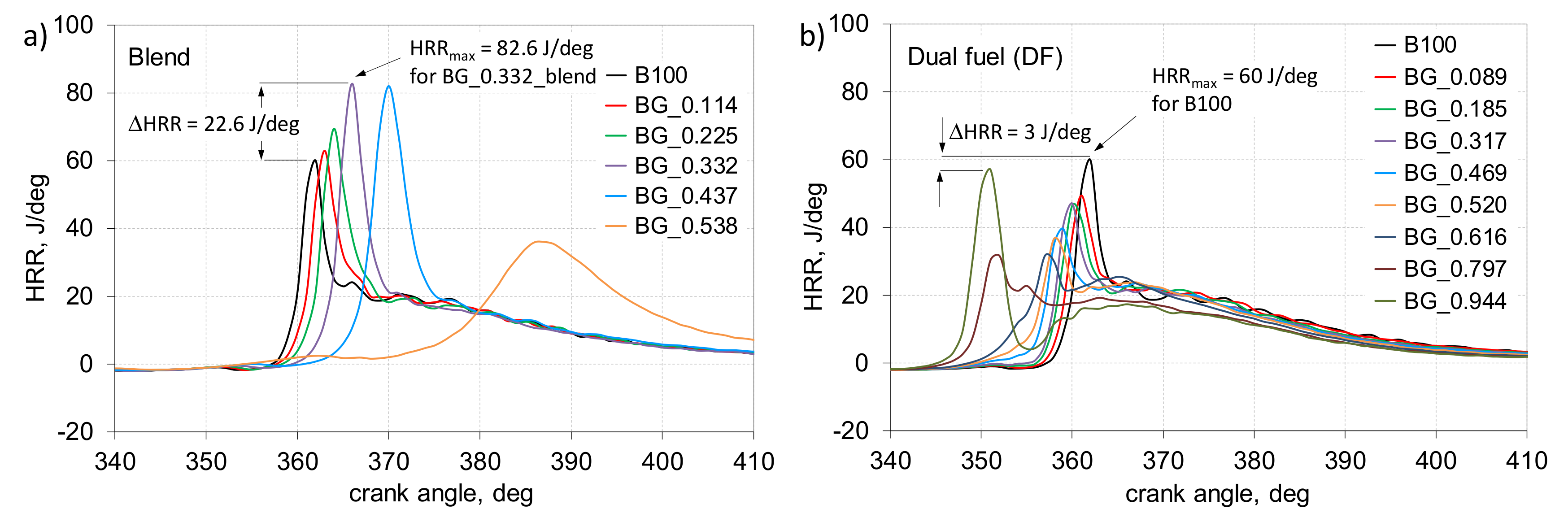
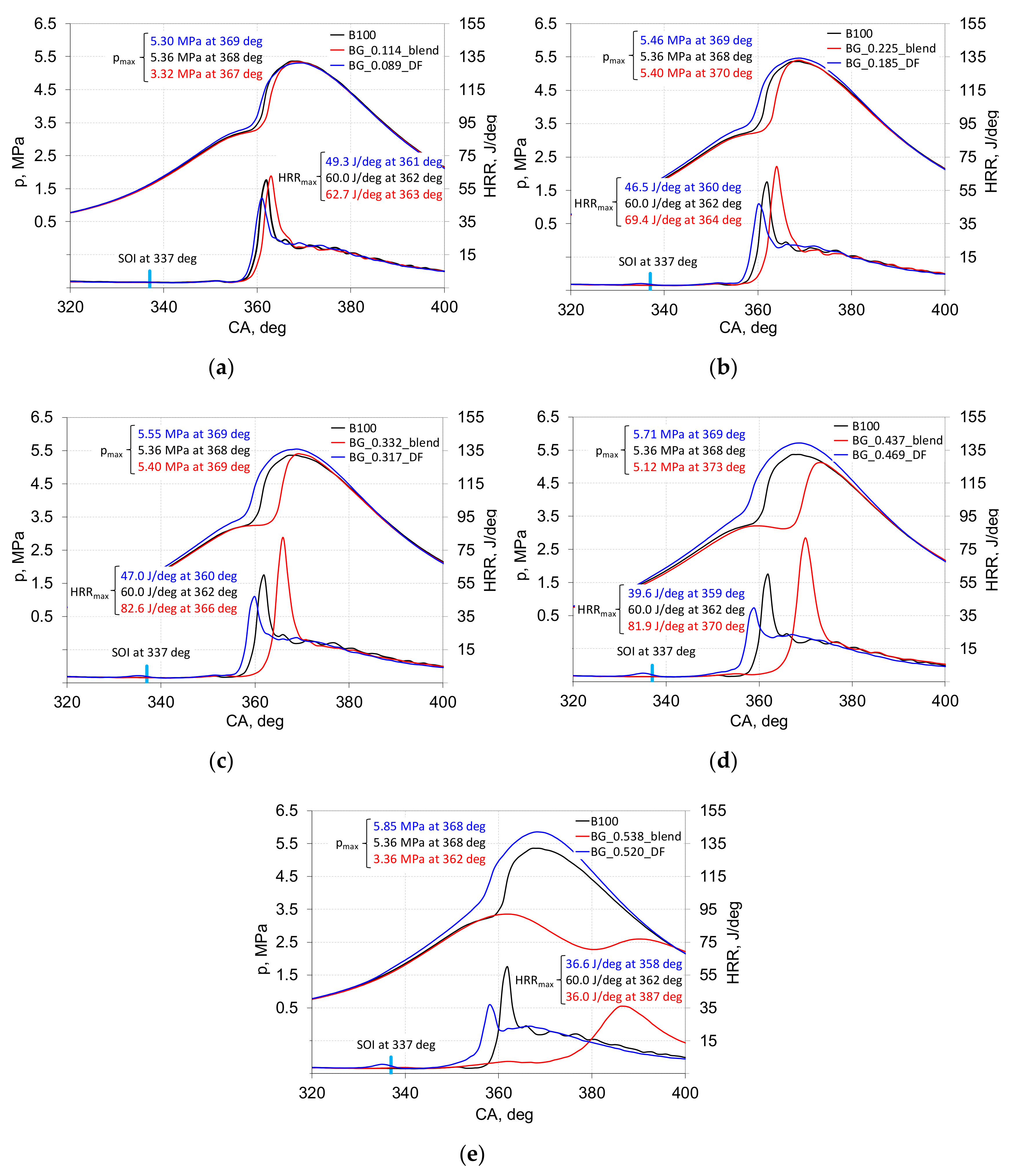
3.1. Biodiesel Combustion Process

In Figure 4, pressure traces for both analyzed combustion modes are presented. In the case of co-combustion biodiesel with gasoline as a blend, there was clearly visible deterioration of the auto-ignition process due to the fraction of low-reactivity fuel. With 0.50 of gasoline fraction in the blend, the combustion process began to fade. In the case of blend BG0.538, the energy share of gasoline was over 50%. Such a large share of gasoline increased the ignition delay time and COVIMEP. This run is representative of the set of 200 consecutive engine work cycles. The spread of the cycles is shown for this case in Figure 9a.
The combustion process in a dual fuel engine was completely different. With the increase in gasoline fraction, a higher peak pressure was obtained because the combustion process started earlier. A similar character of combustion pressure changes was obtained by Park et al. [15].
In Figure 5, the pressure rise rate (dp/dϕ) for analyzed cases are presented. For the co-combustion of fuels as a blend, with the increase in gasoline fraction, the peak value of dp/dϕ was obtained later due to lower average CN of the fuel mixture. In the case of the dual fuel mode, the peak values of pressure rise were obtained earlier. In both cases, the maximal values of (dp/dϕ) did not exceed the maximum value allowable for the compression ignition engine—1 MPa/deg [24,25].
In Figure 6, the results of heat release analysis are presented. This parameter provides information about the rate of conversion of fuel energy to heat in the combustion chamber of the IC engine. In the case of blend combustion, it can be stated that with the increase in gasoline fraction, the maximum value of heat release rate (HRR) was obtained later with a higher value, which was due to an increase in ignition delay. In the case of dual fuel engine with the increase in gasoline fraction up to 0.60, the maximum value of HRR was obtained earlier with lower peak values. For near 0.80 of gasoline, the combustion process started rapidly with very small ignition delay (ID). Blend combustion shifts the peak HRR to higher degree of CA values after TDC, but in the case of DF, shifts in the opposite direction—to CA before TDC—in conditions of a constant angle of biodiesel injection.
As mentioned, during the study we analyzed the co-combustion process of biodiesel and gasoline using two various power systems. In Figure 7, the comparison results of pressure and heat release are presented. For each analyzed case, the co-combustion of fuels is related to the combustion of the reference fuel—biodiesel.
On the basis of the comparative analysis, it can be concluded that both combustion systems transfer the combustion process in opposed directions. In the case of blend combustion, it was delayed, but in the case of dual fuel combustion process, it was accelerated. In the case of more than 0.50 of gasoline in combusted charge, for fuel blends, the combustion process was moved to the already-advanced expansion stroke. The peak HRR was obtained 22 deg after TDC which was definitely too late. It should be noted, however, that the engine was operated with the constant angle of fuel injection.
In the case of direct injection, as in the case of an engine that burns a mixture of fuels, heat is absorbed from the hot air to the evaporation of the fuel. In the time from the start of injection (23 deg bTDC) to the start of combustion, the entire fuel dose takes heat from the cylinder charge. In a dual fuel engine, some of the fuel evaporates during filling and compression, and the smaller dose of biodiesel injected directly takes away proportionally less heat needed for evaporation. In general, the drop in compression pressure before ignition is noticeable for fuels with a significant heat of vaporization, such as ethanol or methanol [23].
In Figure 8, a comparison of specific fuel consumption for both combustion systems is presented. It can be stated that for dual fuel technology with the increase in gasoline fraction the SFC decreased up to 0.62 of gasoline fraction. In the case of blend combustion, for all analyzed fuel fractions, SFC increased in comparison with dual fuel technology. Up to 0.30 of gasoline in an SFC blend was at the same level equal to 230 g/kWh. Exceeding 0.40 of gasoline in the SFC blend rapidly increased due to the significant deterioration of combustion. For the highest gasoline fraction in the blend, the combustion process was delayed. This was accompanied by an increase in exhaust gas temperature. For dual fuel technology, for a higher gasoline fraction value of exhaust gas, the temperature started to decrease due to the early combustion process.

3.2. Combustion Stability

The internal combustion engine is a cyclic working machine. In practice, every engine cycle is different. This is influenced by many factors, such as flow processes, differences in cylinder filling, wave phenomena in the intake system, the quality of spray, inhomogeneity charge and others. Ideally, all cycles would be the same, which would ensure a smooth engine operation. The degree of unrepeatability of subsequent engine cycles is also influenced by the type of fuel used—some are more and others less friendly to the engine. Petroleum fuels are very well tolerated by the engine and burn predictably. Alcoholic fuels, due to their properties, such as high value of heat of evaporation, cause more trouble in controlling the engine. Diesel and biodiesel are designed for auto-ignition engines and gasoline for engines with forced ignition. Currently, intensive researches are being conducted on the possibility of using, for example, gasoline to power auto-ignition engines. It turns out that co-firing fuels with various reactivity, for example, in reactivity controlled compression ignition (RCCI) engines, gives great advantages both in terms of its performance and exhaust purity.
In Figure 9, the cycle variation of engines powered with 0.50 of gasoline using the two mentioned combustion systems is presented. It is clearly visible that in the case of powering by blend, the unrepeatability of cycles was very large but, in the case of dual fuel technology following cycles, they were nearly the same. As a determinant of the unrepeatability of the cycles, the IMEP unrepeatability criterion was used (COVIMEP).
In Figure 10, the comparison results of COVIMEP for analyzed cases are presented. It can be stated that in the case of DF mode with the increase in gasoline fraction, COVIMEP was increased slightly from 2% for biodiesel burning to 4% for 0.95 of gasoline energetic fraction. In the case of blend combustion, for 0.50 of gasoline fraction, the increase in COVIMEP was very significant and it was nearly 13%.
In Figure 11, the results of the relationship between IMEP and peak pressure for both analyzed cases are presented. It is visible that in the case of blend combustion, the spread of value of IMEP was relatively large—from nearly 0.2 MPa up to 0.40 of gasoline fraction. For the highest gasoline fraction (0.50), the spread of IMEP was stretched to over 0.3 MPa with peak pressure not exceeding 4 MPa. It was due to significant deterioration of the combustion process. In the case of dual fuel technology, for all analyzed gasoline fractions, we obtained high quality stability of the combustion process. The spread of IMEP was below 0.1 MPa and the decrease of peak pressure was due to the constant engine torque imposed during the tests.
In Figure 12, the results of the investigation of peak pressure position after TDC are presented. It is visible that, in the case of blend combustion, the position of peak pressure was changed in the direction of large values of CA after TDC due to increase in the ignition delay. For a blend of 0.50 of gasoline, we noticed division into two areas—one with normal ignition and one with no ignition. For dual fuel technology, the peak pressure was obtained in a narrow range of crank angle (CA) degrees.
In Figure 13, the results of probability density of IMEP analysis are presented. It can be stated that with near to 0.10 of gasoline fraction in both combustion systems, the PD (probability density) of IMEP was near the same. From 0.30 of gasoline fraction in the combustion process, extending of the IMEP spread is possible. For 30% and 40% of gasoline fraction, the maximal value of IMEP was obtained in 12%–13% of the whole range. For 0.50 of gasoline, the spread of IMEP already exceeded the acceptable range of variation.
In Figure 14, combustion stages during the combustion process are presented. A completely different impact of combustion technology on the ignition delay is clearly visible. The ignition delay period consists of physical and chemical delay phases which occur simultaneously. The physical delay is the time required for fuel atomization, vaporization and mixing with the air. The second ignition phenomenon is the chemical delay which consists of the pre-combustion reaction of fuel with air [3,26,27,28]. Ignition delay in compression ignition engines has a direct effect on engine efficiency, noise and exhaust emissions. Experimentally, the start of ignition is mainly determined by the first appearance of visible flame on a high speed video recording, or sudden rise in cylinder pressure or temperature caused by the combustion. The ignition delay phase is influenced by in-cylinder pressure, temperature, charge moving in cylinder and misfire among others. A key parameter affecting ID is fuel quality. Burning of the fuel blend causes an increase in ID by increasing the gasoline fraction. The ignition delay increased from 29 to 38 deg of CA, which means an increase by 31% compared to the combustion of the reference fuel. In the case of DF mode, with the increase in gasoline fraction the ID was decreased from 29 to 15 deg of CA, which means a decreased of 48% in comparison with reference fuel. Analyzing combustion duration up to 0.40 of gasoline fraction the combustion duration (CD) was decreased simultaneously. For DF mode, this type of change is in the whole range of the gasoline fraction. In the case of blend burning, when exceeding 0.40 of gasoline fraction in the blend, CD started to increase, exceeding the values for reference fuel. The share of combustion phases, ignition delay and combustion duration can be changed by dividing the dose of the injected fuel [29]. As the research shows, the way to a real impact on the division of the combustion phases was to divide the injected fuel dose directly into the combustion chamber for several doses [30]. Diesel fuel doses, the pilot and the extra dose injected at different times cause the combustion process different in terms of dynamics and duration. Another benefit of dose sharing is improvement of engine efficiency and better ecological features [31].
In Figure 15, results of spread estimation of heat release are presented. It is directly connected with unrepeatability of combustion process in the IC engine. Analyzing the time of ignition delay, determined as the time from the start of injection (SOI) to burn 10% of fuel, it can be stated that during blend combustion with exceeding 0.40 of gasoline fraction the spread of ID started significantly increased. For 0.50 of gasoline in the blend, the ignition delay (ID) (Figure 15) was equal to 38 deg of CA and the spread of this parameter was over 10 deg of CA. It caused very uneven operation of the engine. In the case of DF technology, this phenomenon was near steady state. Analyzing the end of combustion, determined as after burning 90% of the fuel, this spread was higher. Of course, this was expected because it was measured on the already-flat part of MFB curve, but in the case of blend combustion there is a visible and constant increase in unrepeatability along with a larger share of gasoline. In the case of DF, a significant increase in this phenomenon was not noticed.

3.3. Emission Analysis

The emissions of diesel engines are characterized by nitrogen oxides (NOx) and soot. The NOx formation rate is strongly related to the temperature. The formation of NOx can be reduced by decreasing the in-cylinder temperature. However, decreasing the temperature in the combustion chamber also reduces the thermal efficiency of the internal combustion engine. It is well known that the highest efficiency of an engine occurs close to the knock limit when the temperature is also high. Furthermore, it is difficult to match reducing the NOx emissions with decreasing the soot emissions. Appropriate control of combustion the phases could reduce the emissions of both NOx and soot. An appropriate swirl ratio can improve the combustion process and have a positive impact on emissions.
The compression-ignition engines are considered to be a significant source of emissions of toxic exhaust components into the atmosphere, particularly in terms of particulate matter and nitrogen oxide emissions [32,33,34,35]. In recent years, many concepts were developed to optimize the combustion process in IC engines, which provide a reduction in pollutant emissions [36,37,38,39]. One of the promising technologies that have a positive effect on reducing the emission of diesel engines is Reactivity Controlled Compression Ignition (RCCI). This is similar to the homogeneous charge compression ignition (HCCI) mode but provides much more control over the combustion process and provides lower emission [39]. In a dual fuel combustion technology, called RCCI, two fuels with different reactivities are mixed in the engine cylinder. In the presented study, in the case of dual fuel mode, the gasoline was injected into the intake manifold and biodiesel was the fuel responsible for ignition. This paper presents the results of a comparative study of exhaust gas emissions as a result of biodiesel–gasoline co-combustion using two modes—as a blend and as dual fuel combustion. The increase in the share of a gasoline fraction in the combustion process was accompanied by an increase in NOx emissions. In the case of DF technology with a 0.95 share of gasoline, a 100% increase in NOx emissions was noted, because the combustion process takes place much earlier, thus the combustion temperature is much higher than the reference case.
In Figure 16, results of comparative analysis of HC and NOx emission are presented. HC is one of the main pollutants produced from incomplete combustion which enters into the air with the other combustion products [40]. It can be stated that in the case of blend and DF combustion, up to 0.30 of the energetic fraction of gasoline obtained lower HC emissions. This can be explained by the increase in combustion efficiency and, as presented in Figure 17, the spread of start of ignition was very small. Another cause could be accredited to the reduction in the viscosity by adding gasoline that enhanced the spray characteristics and therefore improved the combustion process [41]. After exceeding this share of gasoline, in the case of blend, HC emission was increased which can be connected with lower combustion efficiency. Generally, the increase in the share of gasoline fraction in the combustion process was accompanied by an increase in NOx emissions. In the case of DF technology with a 0.95 share of gasoline, a 100% increase in NOx emissions was noted.
In Figure 17, changes in carbon monoxide and excess air ratio for both analyzed cases are presented.
The carbon monoxide (CO) emission is the result of incomplete fuel combustion. This may be due to lower oxygen concentration and in-cylinder temperature in the vicinity of carbon molecule for complete conversion of CO to CO2. It can be stated that for dual fuel mode with the increase in gasoline fraction, CO emissions decreased, and simultaneously the combustion efficiency increased. For burning of the reference fuel, the CO emission was equal to 2.7% and for 0.95 of gasoline fraction it decreased to 0.67%—a decrease of more than four times. We analyzed emissions of CO for blend combustion—for gasoline fraction lower than 0.4 energetic fraction, the CO emission decreased, but slower than for DF mode. After exceeding this threshold, this emission increased rapidly. For 0.44 gasoline energetic fraction, the emission of CO was at the same level as for biodiesel combustion. In Figure 17, the results of excess air ratio investigation are also presented. In the case of excess air ratio analysis, it can be stated that for DF technology, this parameter slightly increased. These are the results obtained by measuring the air and fuel consumption. The trend of changes in the excess air coefficient with the increase of gasoline share can be combined with the course of SFC changes. In the case of DF technology with the increase in gasoline fraction, the SFC decreased and thus the content of oxygen in the exhaust gas increased. The reverse phenomenon was observed for the combustion of the blend.
Excess air ratio [42]:
λ = ( A / F ) a ( A / F ) s = φ 1
where (A/F)a is the actual proportions of air and fuel, (A/F)s is the stoichiometric proportions of air and fuel and φ is the equivalence ratio.
When considering diesel emissions, soot emissions should not be ignored. In the combustion chamber of the diesel engine, there are zones with very poor and very rich mixtures. The rich fuel zones cause a strong tendency to soot formation. The mechanism of soot formation is very complex and the effect on soot particles formed are influenced by both chemical and physical processes. A temperature of 1600 K is a certain limit in the formation of soot; below this temperature, the soot formation process is intensive but above this temperature, the oxidation processes start to dominate [43].
Figure 18 shows the soot emission characteristics of biodiesel/gasoline combustion using blend or dual fuel technology. The smoke emissions are hazardous emissions from compression ignition engines and are formed in locally fuel-rich, moderate-temperature regions when fuel breakdown occurs in the presence of insufficient oxygen. The soot emissions include the particles of partially burnt fuel, lubricating oil and solid phase suspended particles. It was concluded that dual fuel technology significantly reduces soot emissions in comparison with blend combustion. When running with pure biodiesel, the highest soot emissions were obtained and they were equal to 715 mg/m3. For both combustion modes with about 50% of gasoline fraction, the DF technology causes eight times lower soot emission in comparison with blend combustion. Already, at about 10% of the energy share of gasoline, the dual fuel method reduced soot emissions by 40% and the blend method by only 15%. In the case of blend combustion, a further increase in the share of gasoline does not significantly affect soot emissions. The dual fuel method of biodiesel/gasoline combustion is a more effective method for soot eliminating. This is due to the fact that most of the combustion process is a premix combustion instead of a diffusion combustion, thus avoiding soot formation.
In diesel engines, conditions with high temperatures and which reach fuel mixture zones are highly likely to promote soot formation. Most of the soot forms in the engine’s combustion chamber during the first stages of combustion and it is oxidized during the subsequent phases of combustion. The soot formation process is highly complex and it involves chemical and physical processes, where aromatic hydrocarbons are formed and then converted into particles. Soot particles in the combustion chamber also absorb other gaseous substances.

4. Conclusions

In this paper, the results of our comparative analysis of the co-combustion process of biodiesel with gasoline using two technologies: dual fuel and blend. The results of the analysis of the operational parameters of the engine and the assessment of combustion stability were presented. The results of the exhaust gas analysis were also presented. Based on the analysis of the obtained results, the main conclusions were drawn for operational parameters, combustion stages, combustion stability and emission.
Operational parameters:
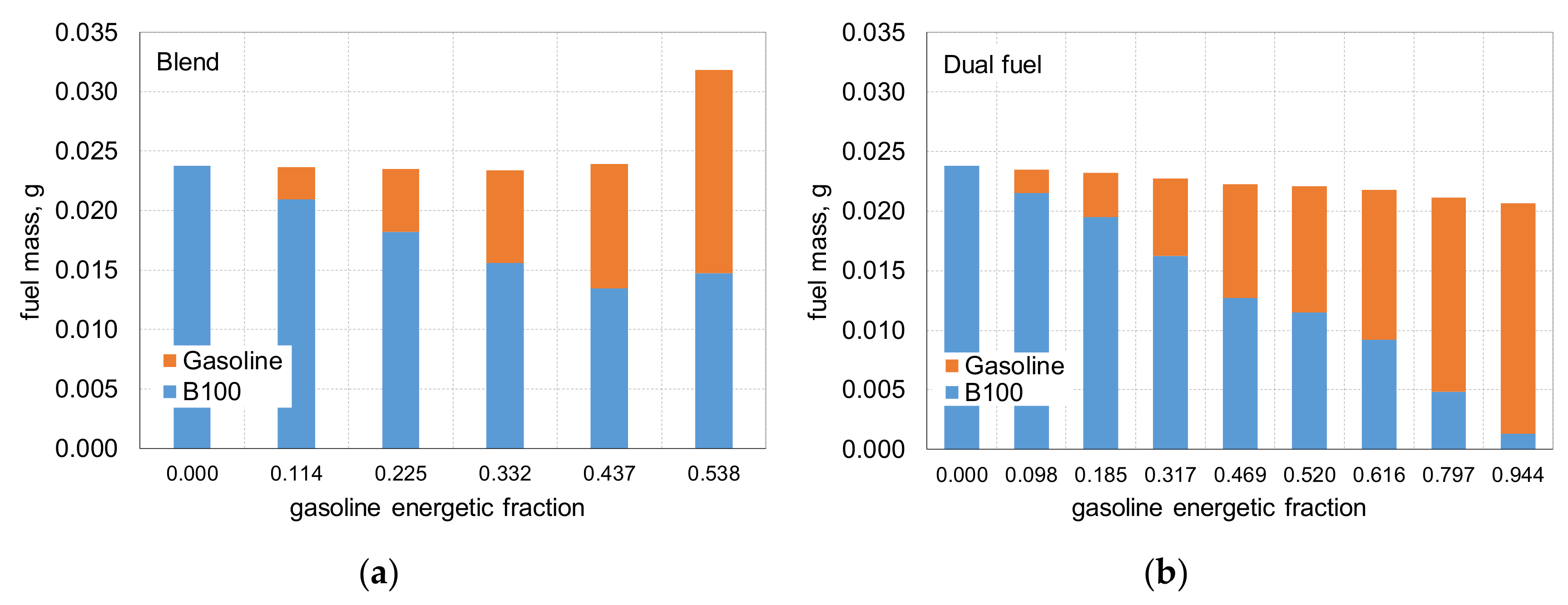
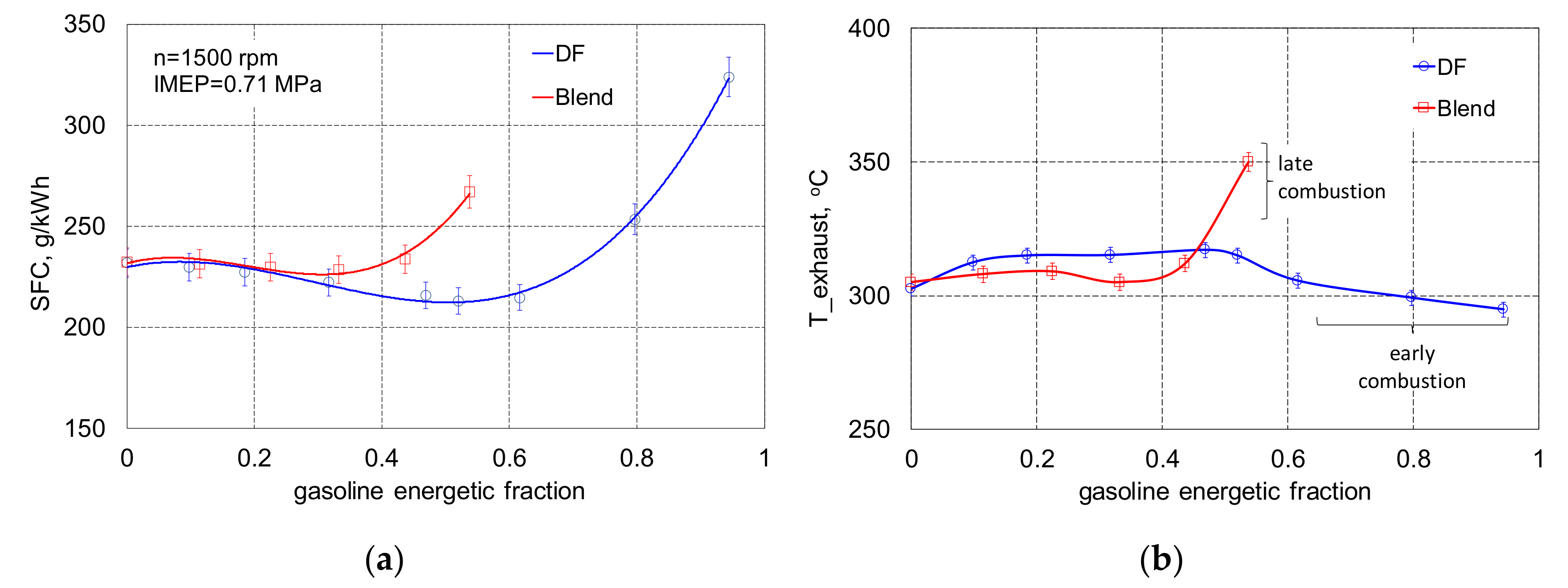
  • For DF technology with an increase in the gasoline fraction, the SFC decreased up to 0.62 of gasoline fraction; in the case of blend combustion for all analyzed gasoline fractions, the SFC was higher in comparison to DF technology, up to 0.3 of gasoline in blend SFC was at the same level—equal to 230 g/kWh.
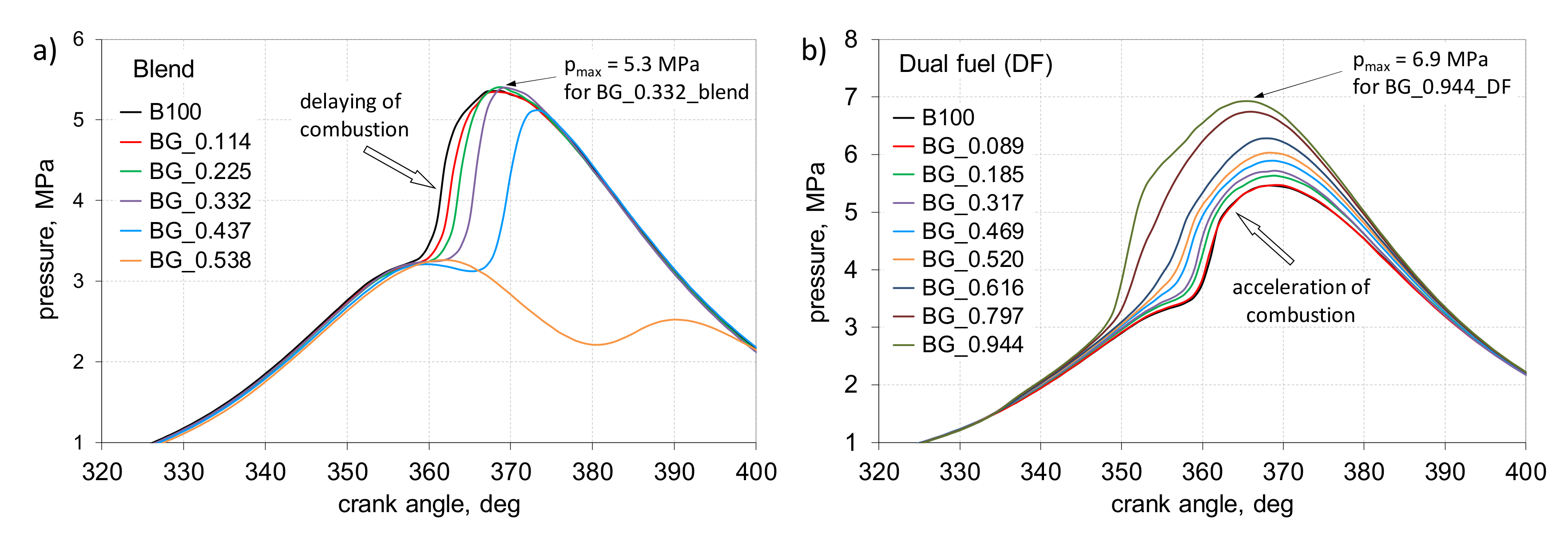
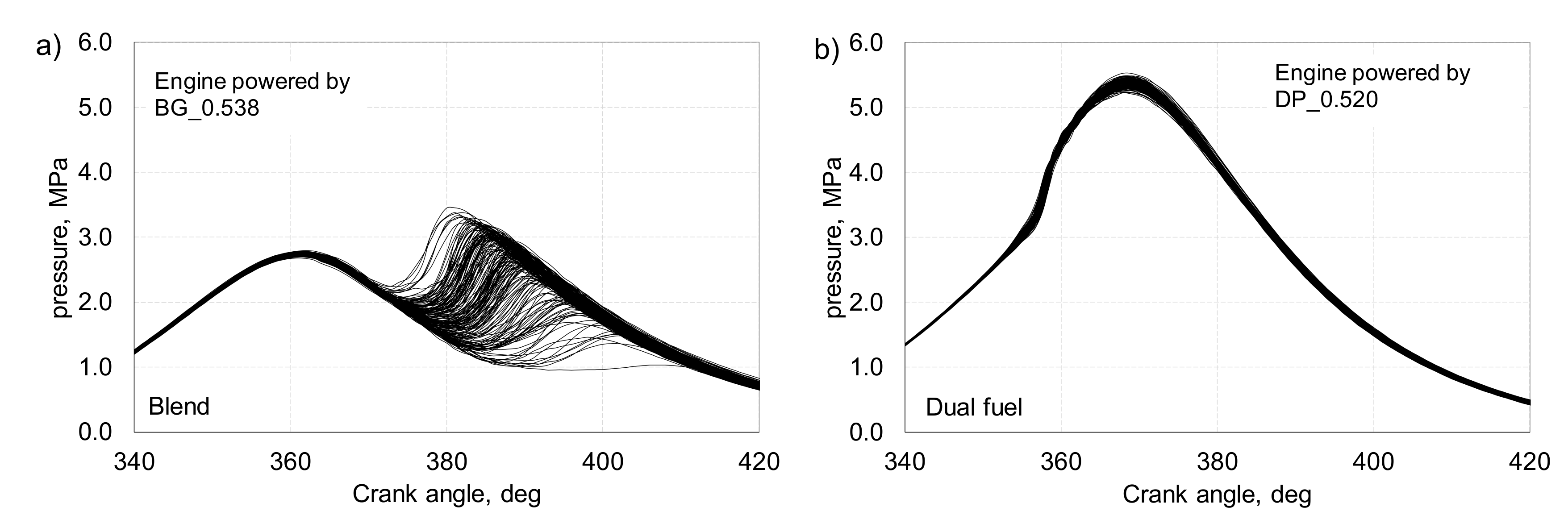
  • With the increase in the gasoline share, for the blend technology the peak of HRR was shifted to the larger deg of CA after TDC, but for DF it moved in the opposite direction.
  • It is possible to co-combustion biodiesel with gasoline in relatively large energetic fractions; for blend it was up to 0.54 and for dual fuel it was near to 0.95.
Combustion stages:
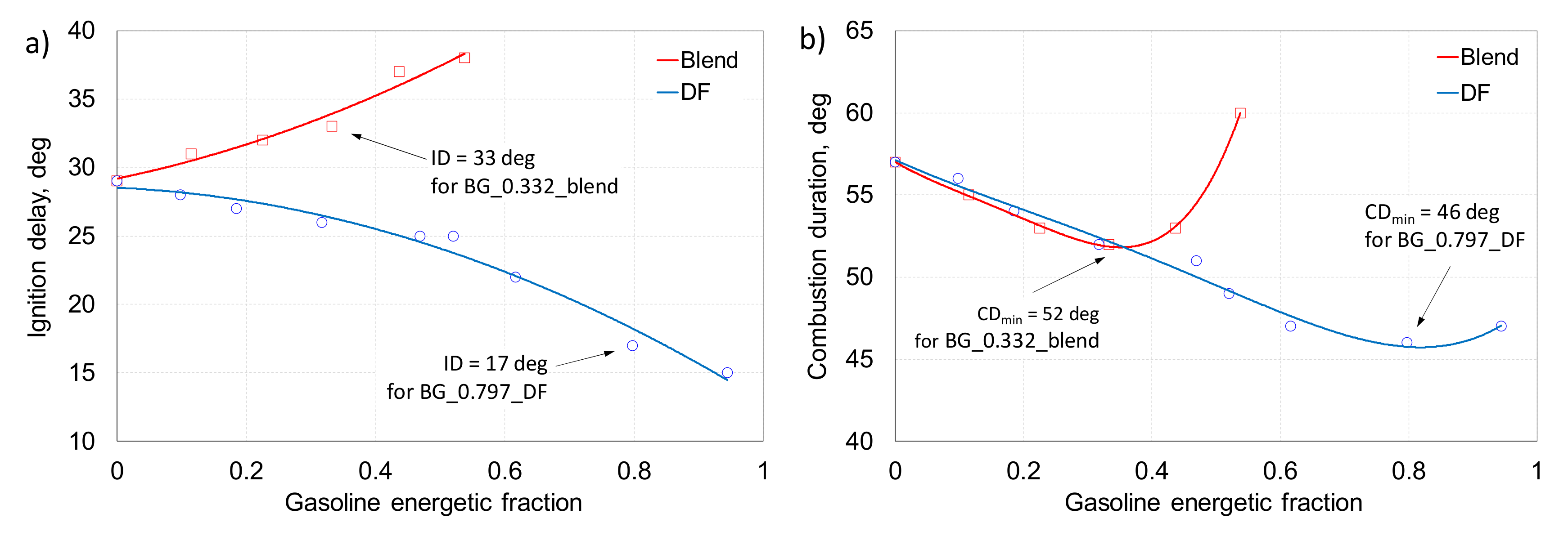
  • The combustion process of biodiesel was characterized by a lower ignition delay in comparison to diesel fuel combustion; the difference was 2 deg of CA.
  • In the case of blend combustion, the ignition delay increased from 29 to 38 deg of CA; for 0.54 of gasoline, ID increased by 31% compared to the combustion of the reference fuel, but for DF technology it was decreased from 29 to 15 deg of CA, and for 0.95 of gasolinem ID decreased by 48%.
  • For blend combustion up to 0.4 of gasoline fraction, the CD decreased; for DF technology, CD decreased up to 80% of gasoline.
Combustion stability:
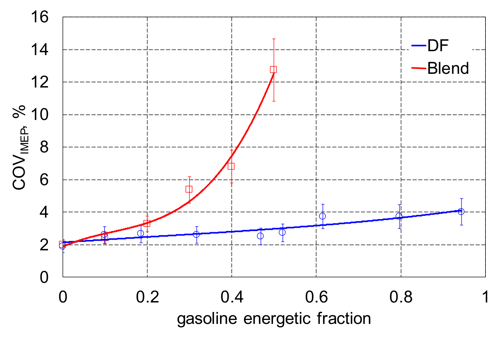
  • In the case of DF mode, with the increase in gasoline fraction, COVIMEP was increased slightly up to 4%, but in the case of blend combustion, for 0.5 of gasoline fraction, the increase in COVIMEP was significant and it was near to 13%.
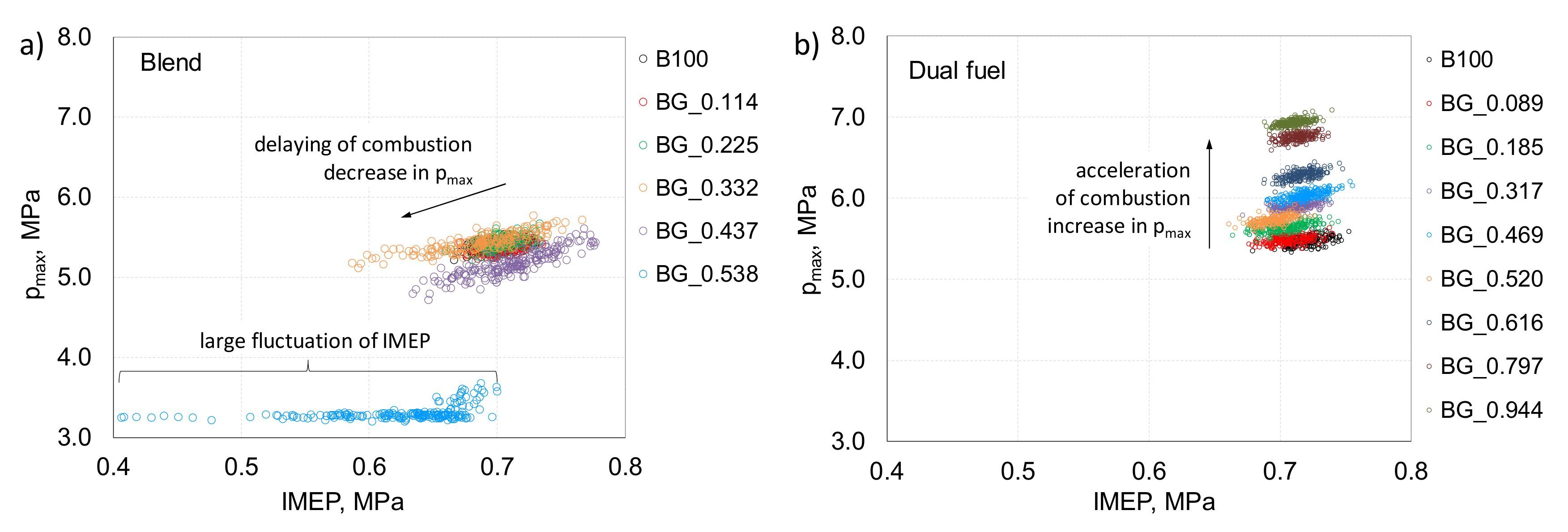
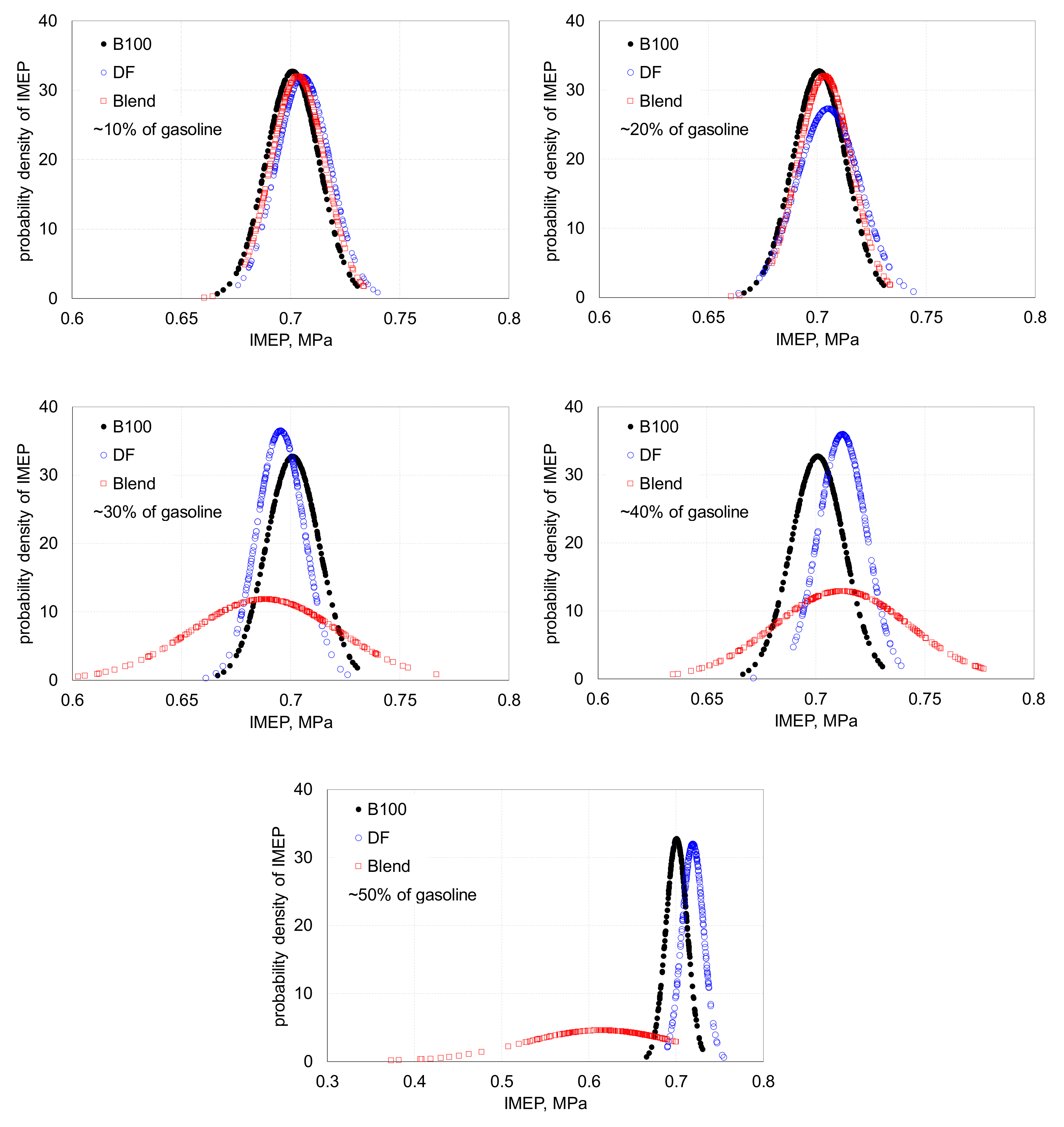
  • Peak pressure vs. IMEP showed that for the DF mode, values of IMEP were in a narrow range of variation, with increased values of peak pressure; in the case of blend combustion, values of IMEP were in a larger spread area with small spread of peak pressure values.
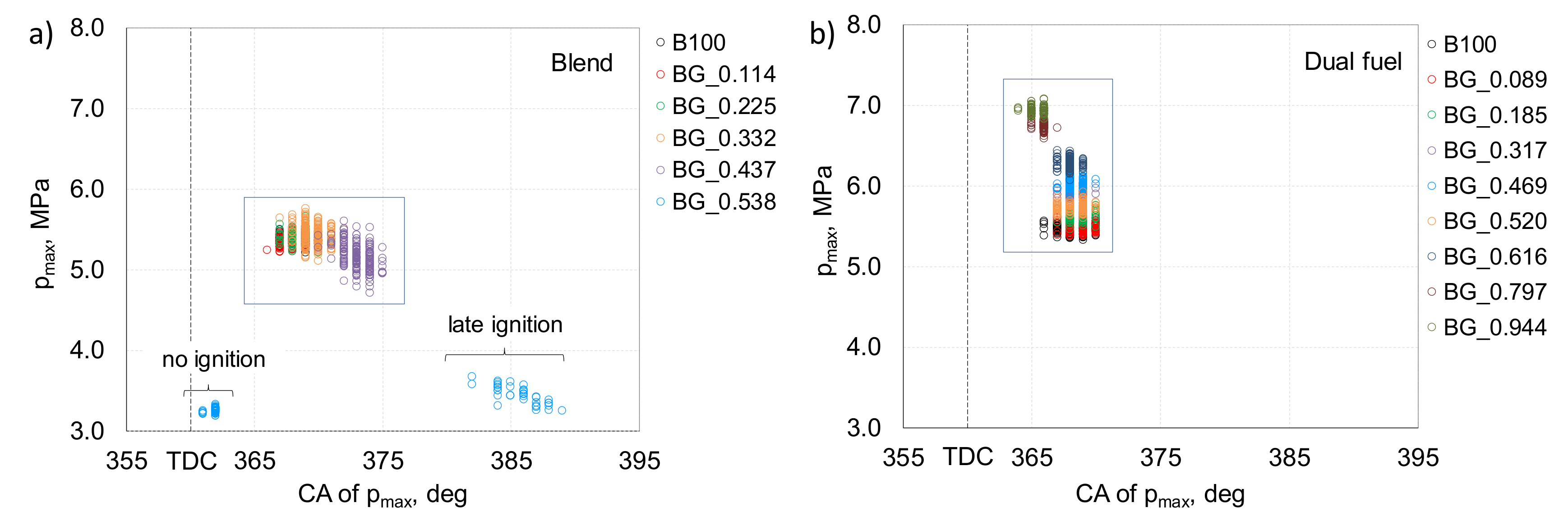
  • In the case of blend combustion, the position of peak pressure was changed in the direction of large values of CA after TDC due to an increase in the ignition delay; for 0.50 gasoline in blend, division into two areas was noticed—one with no ignition and the other in late ignition. For dual fuel technology, the peak pressure was obtained in a narrow range of the crank angle degree.
Emission:
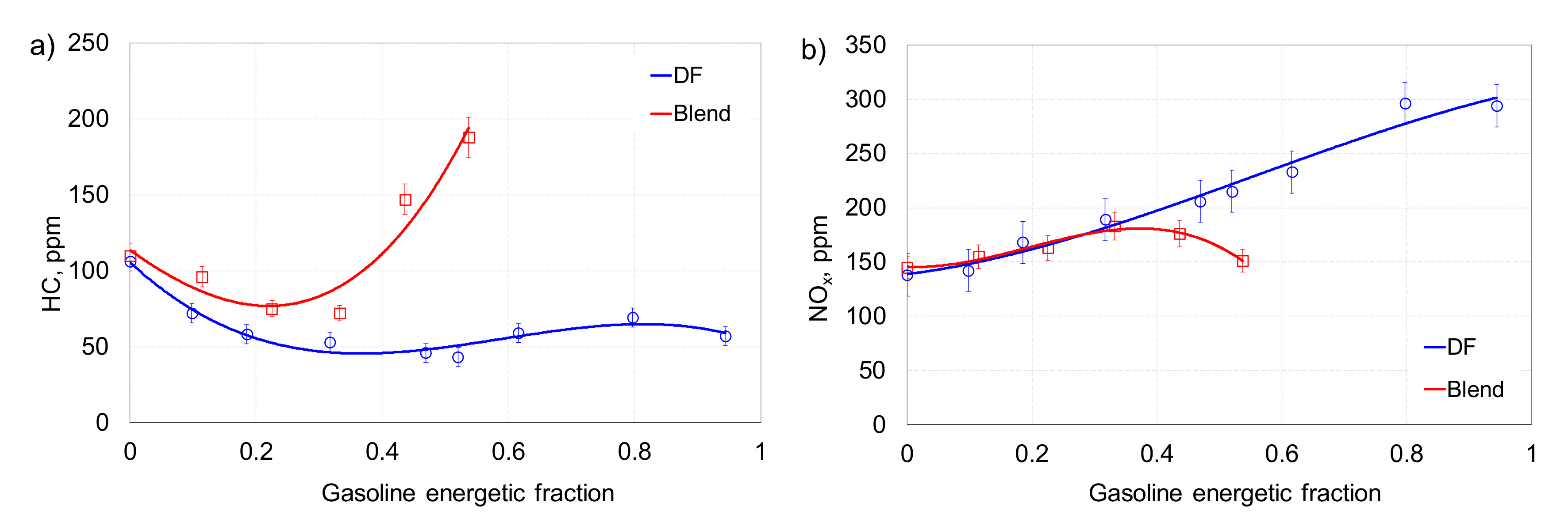
  • For blend and DF combustion, up to 0.30 of energetic fraction of gasoline obtained lower HC emission.
  • The increase in the share of gasoline fraction in the combustion process causes an increase in NOx emissions; DF technology with a 0.95 share of gasoline was characterized by a 100% increase in NOx emission.
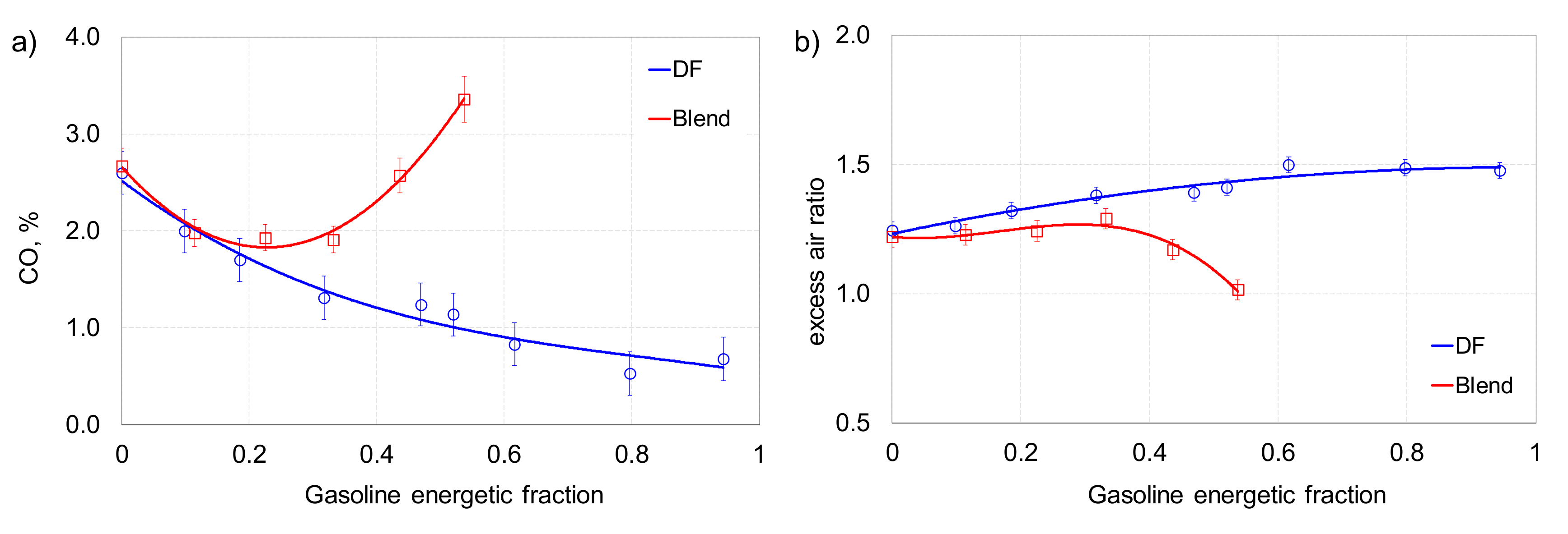
  • For burning of reference fuel, the CO emission was equal to 2.7%, and for 0.95 of gasoline fraction, it decreased to 0.67%—a decrease of more than four times.
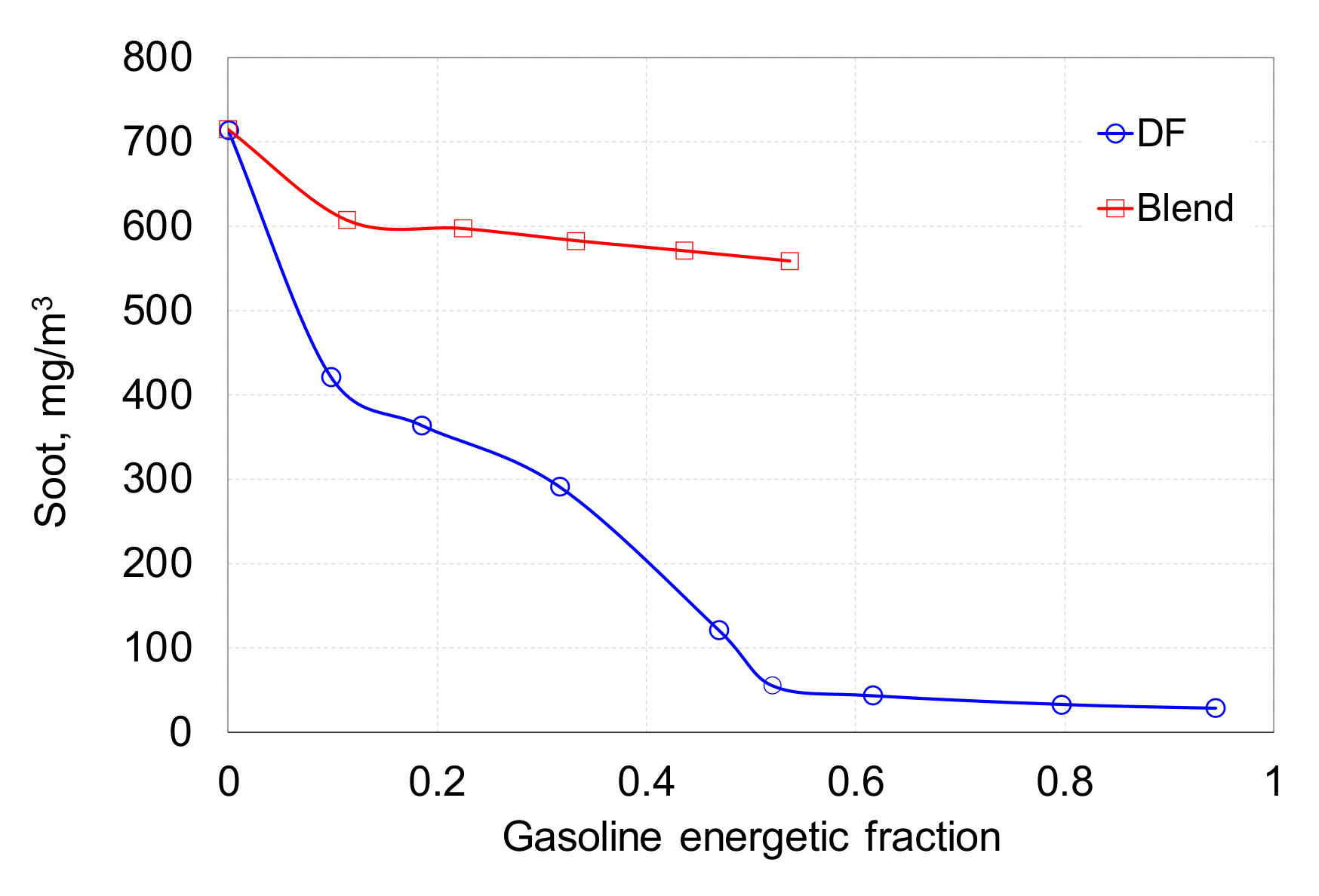
  • For 10% of the energy share of gasoline, the dual fuel method reduced soot emissions by 40% and the blend method by only 15%; for blend burning, a further increase in the share of gasoline does not significantly affect soot emissions.
It can be concluded that the dual fuel system is more beneficial and gives more engine control options for gasoline combustion in compression ignition engines. In the next stage, optimization studies should be carried out. For both combustion systems, the optimal angle of direct injection should be determined for each fuel share. It is also expedient to divide the direct injection dose into pilot dose and main injection. The use of EGR should also be considered.

Author Contributions

Conceptualization, W.T. and A.J.; Data curation, W.T. and A.J.; Formal analysis, W.T.; Investigation, W.T. and A.J.; Methodology, W.T. and A.J.; Writing—original draft, W.T.; Writing—review and editing, W.T. and A.J. Both authors have read and agreed to the published version of the manuscript.

Funding

This research was funded by the Ministry of Science and Higher Education of Poland from the funds dedicated to scientific research No. BS/PB 1-100-3010/2019/P.

Conflicts of Interest

The authors declare no conflict of interest.

Abbreviations

BGBiodiesel-gasoline
CACrank angle, deg
CDCombustion duration, deg
CNCetane number
COVCoefficient of variation, %
DFDual fuel
HCCIHomogeneous charge compression ignition
RCCIReactivity controlled compression ignition
ICInternal combustion
IDIgnition delay, deg
IMEPIndicated mean effective pressure, MPa
LHVLower heating value, MJ/kg
MFB Mass fraction burned, %
PD Probability density, %
SOIStart of injection, deg
SFCSpecific fuel consumption, g/kWh
TDCTop dead center
(A/F)aActual proportions of air and fuel, kg/kg
(A/F)sStoichiometric proportions of air and fuel, kg/kg
ϕCrank angle, deg
λExcess air ratio
φ Equivalence ratio

References

  1. Hoseinpour, M.; Sadrnia, H.; Tabasizadeh, M.; Ghobadian, B. Energy and exergy analyses of a diesel engine fueled with diesel, biodiesel-diesel blend and gasoline fumigation. Energy 2017, 141, 2408–2420. [Google Scholar] [CrossRef]
  2. Zöldy, M.; Török, Á. Road transport liquid fuel today and tomorrow: Literature overview. Period. Polytech. Transp. Eng. 2015, 43, 172–176. [Google Scholar] [CrossRef]
  3. Szabados, G.; Bereczky, Á.; Ajtai, T.; Bozóki, Z. Evaluation analysis of particulate relevant emission of a diesel engine running on fossil diesel and different biofuels. Energy 2018, 161, 1139–1153. [Google Scholar] [CrossRef]
  4. Jamrozik, A.; Tutak, W.; Gnatowska, R.; Nowak, Ł. Comparative analysis of the combustion stability of diesel-methanol and diesel-ethanol in a dual fuel engine. Energies 2019, 12, 971. [Google Scholar] [CrossRef] [Green Version]
  5. Jamrozik, A.; Tutak, W.; Grab-Rogaliński, K. An experimental study on the performance and emission of the diesel/CNG dual-fuel combustion mode in a stationary CI engine. Energies 2019, 12, 3857. [Google Scholar] [CrossRef] [Green Version]
  6. Nam, V.D.; Lim, M.T.; Lim, O. Study on auto-ignition characteristics of gasoline-biodiesel blend fuel in a rapid compression expansion machine. Energy Procedia 2017, 105, 1789–1795. [Google Scholar] [CrossRef]
  7. Putrasari, Y.; Lim, O. Performance and emission of gasoline compression ignition engine fueled with 5 and 20% gasoline-biodiesel blends under single injection strategy. Energy Procedia 2017, 105, 1743–1750. [Google Scholar] [CrossRef]
  8. Putrasari, Y.; Lim, O. A study of a GCI engine fueled with gasoline-biodiesel blends under pilot and main injection strategies. Fuel 2018, 221, 269–282. [Google Scholar] [CrossRef]
  9. Das, S.K.; Kim, K.; Lim, O. Experimental study on non-vaporizing spray characteristics of biodiesel blended gasoline fuel in a constant volume chamber. Fuel Process. Technol. 2018, 178, 322–335. [Google Scholar] [CrossRef]
  10. Adams, C.A.; Loeper, P.; Krieger, R.; Andrie, M.J.; Foster, D.E. Effects of biodiesel–gasoline blends on gasoline direct-injection compression ignition (GCI) combustion. Fuel 2013, 111, 784–790. [Google Scholar] [CrossRef]
  11. Jamrozik, A.; Tutak, W.; Gruca, M.; Pyrc, M. Performance, emission and combustion characteristics of CI dual fuel engine powered by diesel/ethanol and diesel/gasoline fuels. J. Mech. Sci. Technol. 2018, 32, 2947–2957. [Google Scholar] [CrossRef]
  12. Tutak, W.; Jamrozik, A.; Gnatowska, R. Combustion of different reactivity fuel mixture in a dual fuel engine. Therm. Sci. 2018, 22, 1191–1203. [Google Scholar] [CrossRef] [Green Version]
  13. Tutak, W.; Jamrozik, A.; Bereczky, Á.; Lukács, K. Effects of injection timing of diesel fuel on performance and emission of dual fuel diesel engine powered by diesel/E85 fuels. Transprt 2018, 33, 633–646. [Google Scholar] [CrossRef]
  14. Jamrozik, A. The effect of the alcohol content in the fuel mixture on the performance and emissions of a direct injection diesel engine fueled with diesel-methanol and diesel-ethanol blends. Energy Convers. Manag. 2017, 148, 461–476. [Google Scholar] [CrossRef]
  15. Park, S.H.; Yoon, S.H.; Lee, C.S. Bioethanol and gasoline premixing effect on combustion and emission characteristics in biodiesel dual-fuel combustion engine. Appl. Energy 2014, 135, 286–298. [Google Scholar] [CrossRef]
  16. Desantes, J.M.; Payri, R.; Salvador, F.J.; Manin, J. Influence on Diesel Injection Characteristics and Behavior Using Biodiesel Fuels; SAE Technical Paper 2009-01-0851; SAE International: Warrendale, PA, USA, 2009. [Google Scholar] [CrossRef]
  17. Gruca, M. Software for Acquisition of internal combustion engine data. J. Kones 2004, 11, 205–211. [Google Scholar]
  18. Jamrozik, A.; Tutak, W.; Pyrc, M.; Gruca, M.; Kočiško, M. Study on co-combustion of diesel fuel with oxygenated alcohols in a compression ignition dual-fuel engine. Fuel 2018, 221, 329–345. [Google Scholar] [CrossRef]
  19. Yusri, I.M.; Mamat, R.; Najafi, M.G.; Razman, A.; Awad, O.I.; Azmi, W.H.; Ishak, W.F.W.; Shaiful, A.I.M. Alcohol based automotive fuels from first four alcohol family in compression and spark ignition engine: A review on engine performance and exhaust emissions. Renew. Sustain. Energy Rev. 2017, 77, 169–181. [Google Scholar] [CrossRef] [Green Version]
  20. Li, Y.; Gong, J.; Deng, Y.; Yuan, W.; Fu, J.; Zhang, B. Experimental comparative study on combustion, performance and emissions characteristics of methanol, ethanol and butanol in a spark ignition engine. Appl. Therm. Eng. 2017, 115, 53–63. [Google Scholar] [CrossRef]
  21. Xu, Y.; Kang, H.; Gong, J.; Zhang, S.; Li, X. A study on the combustion strategy of gasoline/diesel dual-fuel engine. Fuel 2018, 225, 426–435. [Google Scholar] [CrossRef]
  22. Das, S.K.; Jo, H.; Jwa, K.H.; Lim, O.; Woo, Y. Combustion characteristics of biodiesel blended gasoline fuel in engine like condition using constant volume combustion (CVCC). Energy Procedia 2018, 145, 187–192. [Google Scholar] [CrossRef]
  23. Tutak, W.; Lukács, K.; Szwaja, S.; Bereczky, Á. Alcohol–diesel fuel combustion in the compression ignition engine. Fuel 2015, 154, 196–206. [Google Scholar] [CrossRef]
  24. Aldawood, A.; Mosbach, S.; Kraft, M. HCCI Combustion Control Using Dual-Fuel Approach: Experimental and Modeling Investigations; SAE Technical Paper 2012-01-1117; SAE International: Warrendale, PA, USA, 2012. [Google Scholar] [CrossRef] [Green Version]
  25. Garipov, M.D.; Rezvanov, D.R.; Zinnatullin, R.F. Experimental Study of Spark-Ignited Two-Stroke Heavy Fuel Engine. In Proceedings of the 4th International Conference on Industrial Engineering, Moscow, Russia, 15–18 May 2018; Lecture Notes in Mechanical Engineering, ICIE 2018. Springer: Cham, Switzerland, 2019; pp. 469–485. [Google Scholar]
  26. Kuszewski, H. Experimental study of the autoignition properties of n-butanol–diesel fuel blends at various ambient gas temperatures. Fuel 2019, 235, 1316–1326. [Google Scholar] [CrossRef]
  27. Kuszewski, H. Experimental investigation of the autoignition properties of ethanol–biodiesel fuel blends. Fuel 2019, 235, 1301–1308. [Google Scholar] [CrossRef]
  28. Kuszewski, H.; Jaworski, A.; Ustrzycki, A.; Lejda, K.; Woś, P. Use of the constant volume combustion chamber to examine the properties of autoignition and derived cetane number of mixtures of diesel fuel and ethanol. Fuel 2017, 200, 564–575. [Google Scholar] [CrossRef]
  29. Jamrozik, A.; Tutak, W.; Gnatowski, A.; Gnatowska, R.; Winczek, J.; Sosnowski, M. Modeling of Thermal Cycle CI Engine with Multi-Stage Fuel Injection. Adv. Sci. Technol. Res. J. 2017, 11, 179–186. [Google Scholar] [CrossRef]
  30. Merkisz, J.; Waligórski, M. Strategy of the combustion process diagnosis in direct injection engines. Procedia Eng. 2014, 96, 294–301. [Google Scholar] [CrossRef] [Green Version]
  31. Stelmasiak, Z.; Matyjasik, M. Simulation of the combustion in a dual fuel engine with a divided pilot dose. Combust. Engines 2012, 4, 43–54. [Google Scholar]
  32. Merkisz, J.; Fuć, P.; Lijewski, P.; Pielecha, J. Actual emissions from urban buses powered with diesel and gas engines. Transp. Res. Procedia 2016, 14, 3070–3078. [Google Scholar] [CrossRef] [Green Version]
  33. Stelmasiak, Z.; Matyjasik, M. Exhaust emissions of dual fuel self-ignition engine with divided initial dose. Combust. Engines 2013, 154, 944–952. [Google Scholar]
  34. Rimkus, A.; Žaglinskis, J.; Stravinskas, S.; Rapalis, P.; Matijošius, J.; Bereczky, Á. Research on the combustion, energy and emission parameters of various concentration blends of hydrotreated vegetable oil biofuel and diesel fuel in a compression-ignition engine. Energy 2019, 12, 2978. [Google Scholar] [CrossRef] [Green Version]
  35. Rimkusa, A.; Matijošius, J.; Bogdevičius, M.; Bereczky, Á.; Török, Á. An investigation of the efficiency of using O2 and H2 (hydrooxile gas-HHO) gas additives in a ci engine operating on diesel fuel and biodiesel. Energy 2018, 152, 640–651. [Google Scholar] [CrossRef]
  36. Li, J.; Yang, W.M.; An, H.; Zhao, D. Effects of fuel ratio and injection timing on gasoline/biodiesel fueled RCCI engine: A modeling study. Appl. Energy 2015, 155, 59–67. [Google Scholar] [CrossRef]
  37. Tong, L.; Wang, H.; Zheng, Z.; Reitz, R.; Yao, M. Experimental study of RCCI combustion and load extension in a compression ignition engine fueled with gasoline and PODE. Fuel 2016, 181, 878–886. [Google Scholar] [CrossRef]
  38. Reitz, R.D.; Duraisamy, G. Review of high efficiency and clean reactivity controlled compression ignition (RCCI) combustion in internal combustion engines. Prog. Energy Combust. Sci. 2015, 46, 12–71. [Google Scholar] [CrossRef] [Green Version]
  39. Szwaja, S.; Ansari, E.; Rao, S.; Szwaja, M.; Pyrc, M. Influence of exhaust residuals on combustion phases, exhaust toxic emission and fuel consumption from a natural gas fueled spark-ignition engine. Energy Convers. Manag. 2018, 165, 440–446. [Google Scholar] [CrossRef]
  40. Kapusta, Ł.J.; Teodorczyk, A. Numerical simulations of dual fuel combustion in a heavy duty compression ignition engine. Combust. Engines 2015, 163, 47–56. [Google Scholar]
  41. Gad, M.S.; EL-Seesy, A.I.; Radwan, A.; He, Z. Enhancing the combustion and emission parameters of a diesel engine fueled by waste cooking oil biodiesel and gasoline additives. Fuel 2020, 269, 117466. [Google Scholar] [CrossRef]
  42. Heywood, J.B. Internal Combustion Engine Fundamentals; McGraw-Hill Book Company: New York, NY, USA, 2018. [Google Scholar]
  43. Bockhorn, H. Soot Formation in Combustion: Mechanisms and Models; Springer: Berlin/Heidelberg, Germany, 1994. [Google Scholar]
Figure 1. Power systems of dual fuel engine, (a) supply by blend of fuels, (b) supply by two separate systems.
Processes 08 01499 g001
Figure 2. Diagram of the experimental setup. 1—engine, 2—diesel fuel injector, 3—gasoline fuel injector, 4—in cylinder pressure sensor, 5—intake air flowmeter, 6—air filter, 7—cooling fan, 8—exhaust gases temperature sensor, 9—PC with data acquisition system, 10—crank angle sensor. (a) experimental setup, (b) the test engine.
Processes 08 01499 g002
Figure 3. Doses of fuel for various energetic fraction used during the tests, (a) blend, (b) dual fuel.
Processes 08 01499 g003
Figure 4. Pressure courses for blends (a) and dual fuel (b) combustion mode.
Processes 08 01499 g004
Figure 5. Pressure rise rate for blends (a) and dual fuel (b) combustion modes.
Processes 08 01499 g005
Figure 6. Heat release rate for blends (a) and dual fuel (b) combustion modes.
Processes 08 01499 g006
Figure 7. The impact of combustion mode on pressure and heat release rate in the case of biodiesel-gasoline combustion, (a) ~10% of gasoline, (b) ~20% of gasoline, (c) ~30% of gasoline, (d) ~40% of gasoline, (e) ~50% of gasoline.
Processes 08 01499 g007
Figure 8. Specific fuel consumption (SFC) (a) and exhaust gases temperature (T_exh) (b).
Processes 08 01499 g008
Figure 9. Cycle variation of engine powered by BG blend (a) and as DF engine (b).
Processes 08 01499 g009
Figure 10. Cycle variation of engine powered by blend and as dual fuel engine.
Processes 08 01499 g010
Figure 11. Results of peak pressure vs. IMEP are presented for blends (a) and dual fuel (b) combustion modes.
Processes 08 01499 g011
Figure 12. The position of the peak pressure after TDC for blends (a) and dual fuel (b) combustion modes.
Processes 08 01499 g012
Figure 13. Probability density (PD) of IMEP for biodiesel-gasoline combustion.
Processes 08 01499 g013
Figure 14. Stages of combustion, ignition delay (a) and combustion duration (b).
Processes 08 01499 g014
Figure 15. Stability of heat release.
Processes 08 01499 g015
Figure 16. Emission of unburned hydrocarbons (HC) (a) and nitrogen oxides (NOx) (b).
Processes 08 01499 g016
Figure 17. Emission of carbon monoxides (CO) (a) and excess air ratio (b).
Processes 08 01499 g017
Figure 18. Soot emission changes for dual fuel and blend mode.
Processes 08 01499 g018
Table 1. Main engine parameters.
ParameterValue
Number of cylinders1
Bore90 mm
Stroke90 mm
Displaced volume0.573 dm3
Compression ratio17:1
Crankshaft rotational speed1500 rpm
Biodiesel injection pressure21 MPa
Biodiesel injection timing23 deg bTDC
Maximum rated power7.4 kW
Table 2. Fuels’ properties [19,20,21,22,23].
PropertiesDieselBiodieselGasoline
Molecular formulaC14H30CH3(CH2)nCOOH3CnH1.87n
Molecular weight170–198~294114.15
Surface tension (mN/m @ 15 °C)26.931.121.60
Cetane number515610–15
Research Octane Number20–30-95
Lower heating value, (MJ/kg)41.737.142.7
Density at 20 °C, kg/m3856855745
Viscosity at 25 °C, (mPa s)2.84.510.6
Heat of evaporation, (kJ/kg)260250320
Stoichiometric air fuel ratio14.712.514.7
Autoignition temperature, (°C)300–340363420
Flash point, (°C)78>101−43
Hydrogen content, wt %1312.114
Carbon content, wt %8777.186
Oxygen content, wt %010.80
Publisher’s Note: MDPI stays neutral with regard to jurisdictional claims in published maps and institutional affiliations.

