Article

The Influence of the Blade Outlet Angle on the Flow Field and Pressure Pulsation in a Centrifugal Fan

College of Mechanical and Electronic Engineering, Shandong University of Science and Technology, Qingdao 266590, China
*
Author to whom correspondence should be addressed.
Processes 2020, 8(11), 1422; https://doi.org/10.3390/pr8111422
Submission received: 29 September 2020 / Revised: 4 November 2020 / Accepted: 5 November 2020 / Published: 8 November 2020

Abstract

:
This paper takes centrifugal fan as the research object and establishes five impeller models with different blade outlet angles. By means of computational fluid dynamics (CFD), the external characteristics of the centrifugal fan and the internal characteristics, including the velocity, pressure, and turbulent energy distribution, at the middle span plane of the impeller or fan were obtained and compared. In addition, the pressure fluctuations surrounding the impeller outlet were also analyzed. The results showed that the change of the blade outlet angle of the centrifugal fan had a great influence on the performance; the total pressure and efficiency of the fan were the highest when the outlet angle of the blade was increased to 29.5° under the design flow rate; and the influence of the outlet angle on the fan performance was different in off-design conditions. On the other hand, at different flow rates, the change of the internal flow field with the increase of the outlet angle was different. For the pressure fluctuation of the fan, by increasing the blade outlet angle properly under high flow conditions, the fluctuation amplitude of the fan at the blade frequency and its frequency multiplication could be reduced, which is conducive to decreasing the impeller noise. The research results have good guiding significance regarding the design of the pneumatic performance and noise reduction performance of centrifugal fans.

1. Introduction

Fans belong to the category of general machinery and are widely used in various industries of national economy. They are indispensable equipment for industrial and agricultural production. According to statistics, the power consumption of wind turbines accounts for 8–10% of the total power generation in China (Chen [1]). At present, centrifugal fans occupy a large proportion in China’s energy system. Therefore, it is of great significance to research and improve the pneumatic performance of fans for energy saving. However, in the process of optimizing the performance of fans, the traditional experimental methods have long cycles and high cost, and it is difficult to visually display the gas distribution inside a fan. Therefore, a CFD (Computational Fluid Dynamics) numerical simulation technology that can effectively reduce the sample size of experimental design and capture the details of flow inside the fan more specifically, has increasingly caught the interest of scholars. Many scholars have used numerical simulation technology to study centrifugal fans (Zhang et al. [2]; Zhou et al. [3]; Lin et al. [4]; Yu et al. [5]; Kishokanna et al. [6]).
The impeller is the main moving part of a centrifugal fan, and the structural parameters of the impeller include the blade shape, blade profile, outlet width, number of blades, inlet and outlet diameter, etc. An excellent impeller design is helpful to improve the aerodynamic performance of the fan. At present, many scholars have studied the influence of certain impeller parameters on the aerodynamic performance of fans.
Li et al. [7] studied the influence of blade shapes on the performance of high specific speed centrifugal fans, and found that the blockage phenomenon at the blade outlet of impeller with plate blade and the turbulent kinetic energy inside the volute were weakened under the condition of a large flow rate, so that the performance of the fan with plate blade was better than that of the airfoil blade.
Wu et al. [8] compared the performance of a centrifugal fan with different blade profiles, and found that the centrifugal fan with a double-arc blade was higher in the efficiency and total pressure under the design condition, but the axial power consumed by equal deceleration blade was smaller. However, under the condition that other parameters of the fan remain unchanged, the internal flow of the fan with an equal deceleration blade was more uniform under the condition of low flow.
Jian et al. [9] found that when the blade outlet width changed, various losses of the fan increased, and the efficiency decreased. With the decrease of the blade outlet width, the flow-pressure curve of the fan shifted to the lower left and the pressure decreased with the increase of the flow rate. This provides a reference for the design of the outlet width of the impeller and the reconstruction of the impeller. Liu et al. [10] found that the aerodynamic performance of the fan can be improved by increasing the number of blades and the diameter of the blade outlet. The optimized fan with a 12-blade number and increased blade outlet diameter was better than the prototype fan in terms of the total pressure and efficiency.
In addition, some scholars studied the interaction among several structural parameters of the impeller. For example, Esra et al. [11] used a neural network method to determine the optimal family of the impeller inlet and outlet radius and inlet and outlet angle to reduce the noise level in the early stage of fan design. Meng et al. [12] studied the influence of three blade structure parameters on the performance of a centrifugal fan, which were inlet angle, outlet angle, and blade number, and obtained that the best combination of the three blade structure parameters using the response surface model (RSM) optimization method. The maximum efficiency was 93.7%.
Shi et al. [13] optimized the combination of the impeller and guide vane by studying the internal flow law of fans and combining this with numerical calculation results. They found that the streamline in the optimized guide vane was uniform and that the vorticity was reduced compared with the original guide vane. HEO et al. [14] analyzed the aerodynamic characteristics of a centrifugal fan with additional splitter blades in the impeller by using three-dimensional Reynolds-averaged Navier–Stokes (RANS). The global Pareto optimal frontier for centrifugal fan design was obtained by using a hybrid multi-objective evolutionary algorithm and response surface approximation model.
As the main parameter of impeller, the blade outlet angle of centrifugal fans has also been studied by scholars. Wang et al. [15] optimized the fan design based on an orthogonal experimental design method and CFD numerical simulation and obtained the relative optimal combination model of the impeller geometric parameters and speed. Through the range analysis of the calculation results, they found that the blade outlet angle had the greatest impact on the fan efficiency.
Recently, Swe et al. [16] discussed the flow characteristics of centrifugal fans with different blade outlet angles using the CFD numerical simulation method. The results showed that when the blade outlet angle was 25°, the steady flow and unsteady flow were more uniform, and the flow distribution in the circumferential direction had little change. Yu et al. [17] also studied the effect of the blade outlet angle on the performance of a multi-blade centrifugal fan, and found that the wind pressure and efficiency of the fan increased in the flow range of 420–725 m3/h with the increase of the blade exit angle, and properly increasing the blade outlet angle can reduce the pulsation amplitude of the fan at the blade frequency and its multiplier frequency.
Although many scholars have studied the blade outlet angle on the centrifugal fan, few have studied the effect of the blade outlet angle on the internal flow field and pressure fluctuation of the straight blade fan. In this paper, a type of straight plate blade fan was selected as the research model. Then, on the basis of the original blade outlet angle, five outlet angles (26.5°, 28°, 29.5°, 31°, and 32.5°) were obtained, and the geometric model was established using SolidWorks software. ANSYS CFX software was used for the numerical simulation, and the feasibility of the calculation results was verified by experiments. Through the software post-processing, the influence of different blade outlet angles on the internal flow field and performance of the centrifugal fan was studied. The amplitudes of fan blades with different outlet angles were obtained and analyzed using fast Fourier transform. The research results can provide certain reference values for the efficient, safe, and stable operation of a centrifugal fan.

2. Research Model and Simulation Method
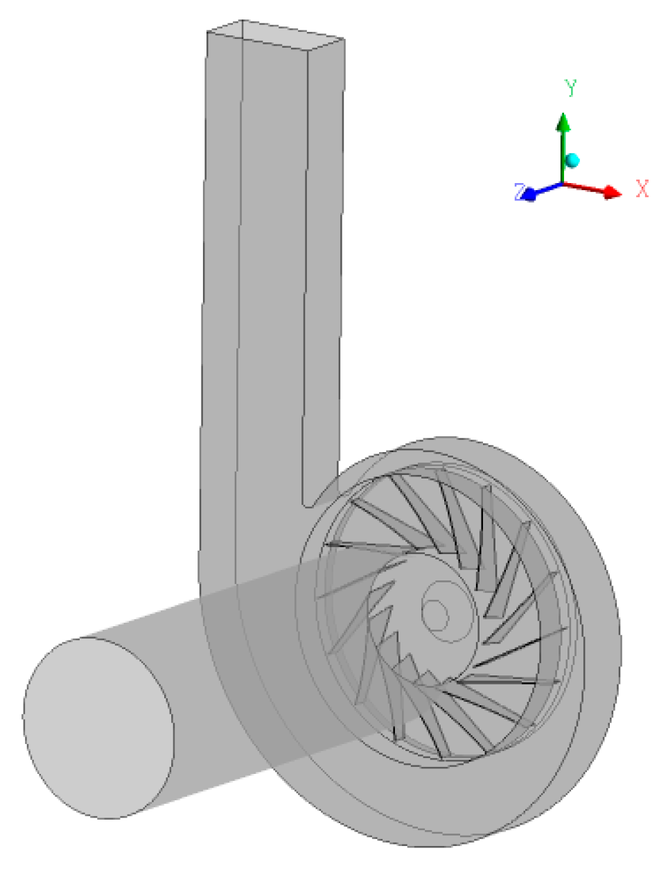
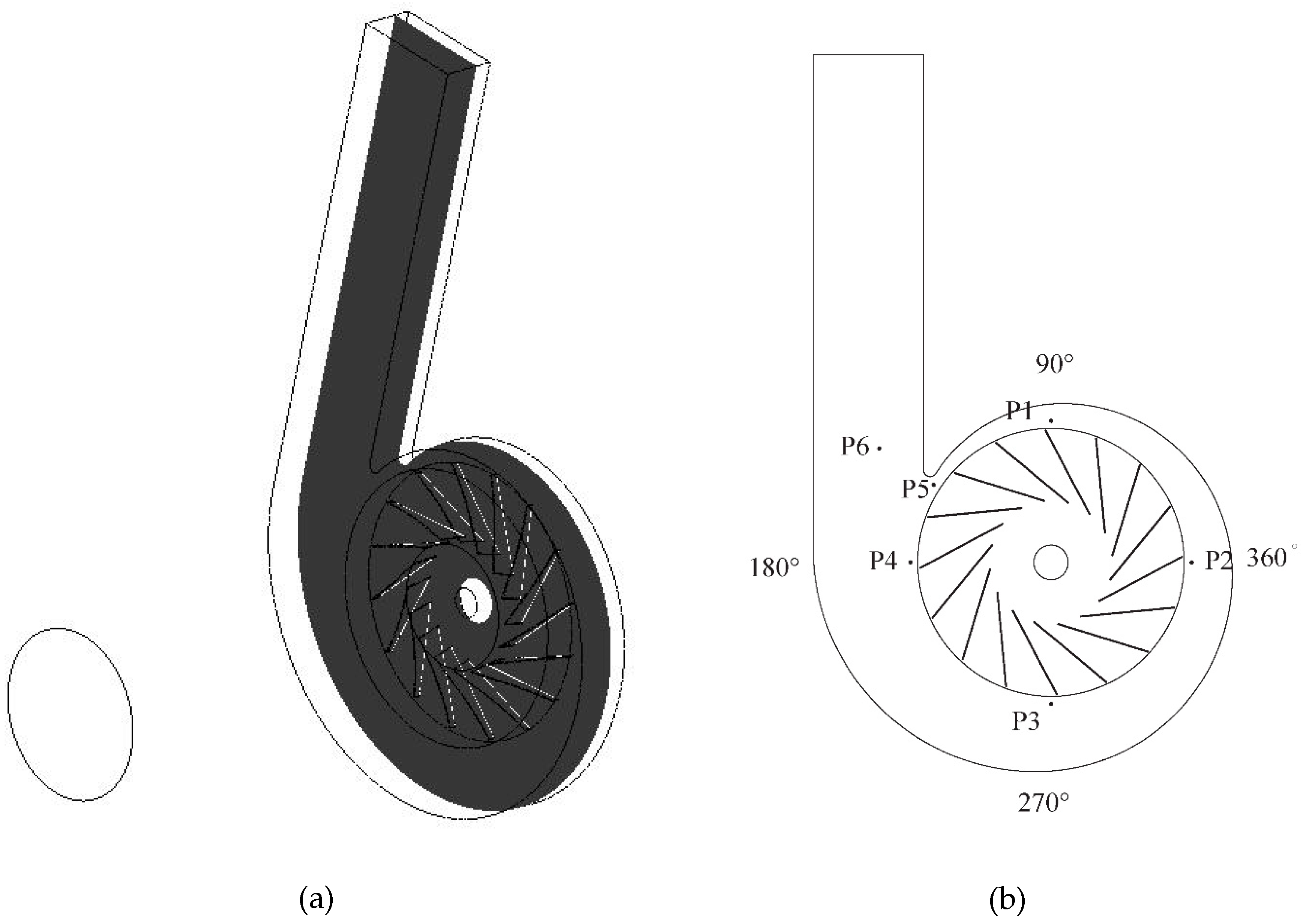
2.1. Research Model

This paper took a certain type of centrifugal fan as the research model, and the main design parameters of the fan are shown in Table 1.
The strategy of this paper was to change the blade outlet angle of the original fan model, and its specific impeller parameters are shown in Table 2. The overall geometric model was established in SolidWorks as shown in Figure 1.

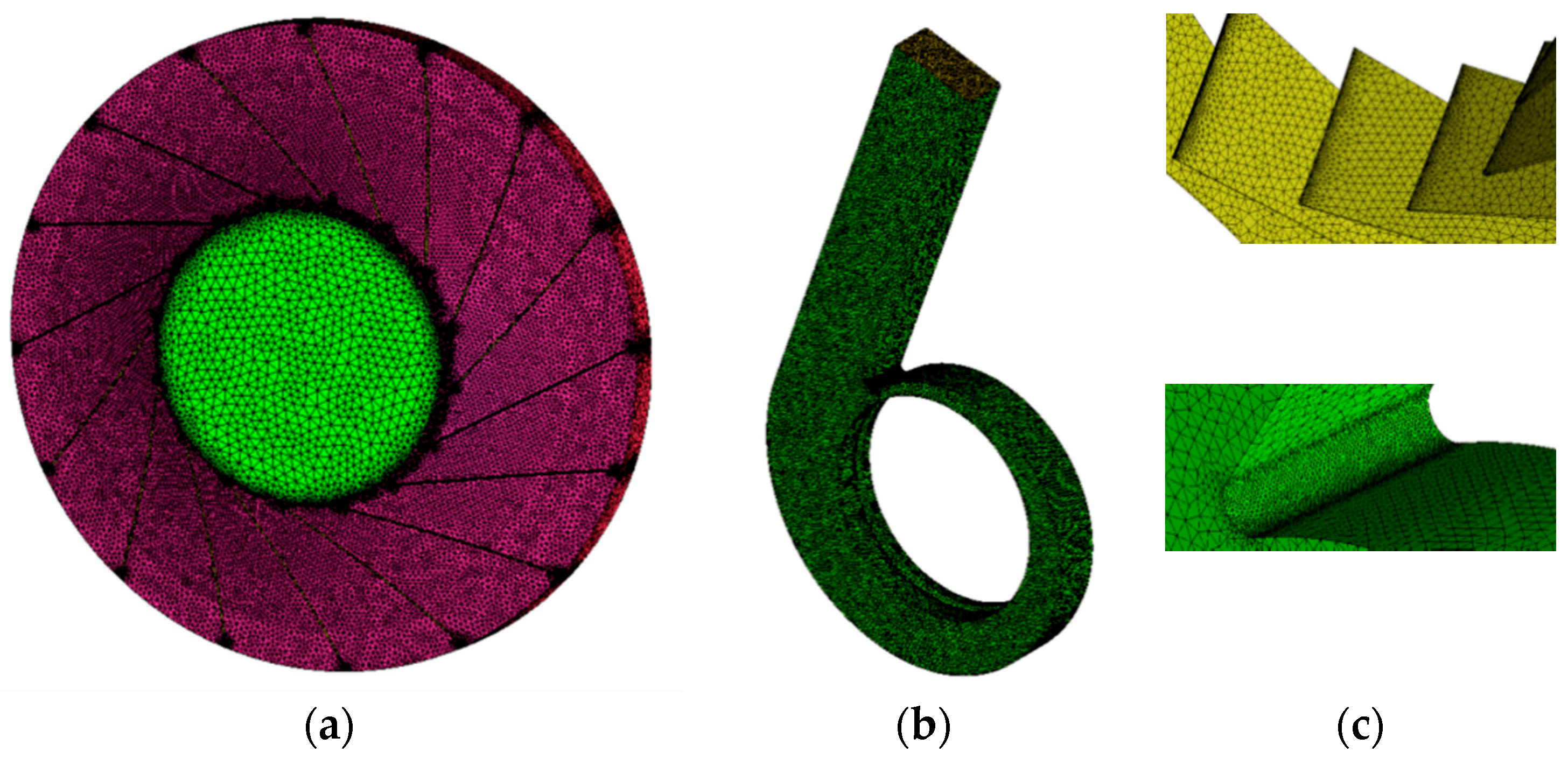
2.2. Mesh and Check of Grid Independence

In this paper, SolidWorks was used for the three-dimensional modeling of the centrifugal fan. In the process of modeling, the geometric model of the original fan was simplified, and some unimportant chamfers, fillets, and gaps were ignored. Based on this, the flow-path model of the centrifugal fan was established. The flow-path model was divided into three parts: air inlet flow-path, impeller flow-path and volute flow-path, and they were combined to form the centrifugal fan model. To ensure the real working condition of the air flow, the inlet and outlet flow-path model were extended properly.
After completing the establishment of the fan model, the mesh generation of the model began. Due to the simplicity of the axisymmetric model of the fan inlet section, the hexahedron structure was used for mesh generation. However, the impeller and volute were meshed with the tetrahedron structure due to the complexity of their flow passages, and the meshing of impeller and volute is shown in Figure 2. To make the numerical simulation as close to the actual situation as possible, all boundary layer grids were refined to meet the requirements of the wall function method. The minimum orthogonal angle of the mesh was greater than 27°, and the maximum extension ratio was less than 2.1, which will ensure high mesh quality.
Table 3 shows the grid independence verification results of the centrifugal fan at design points, in which the total pressure and efficiency were obtained under five different numbers of grids. When the number of grids increased from 3,284,561 to 495,126, the total pressure and efficiency tended to be stable. Based on the accuracy of the simulation results and the cost of the computing time, the scheme of No. III was finally adopted.

2.3. Simulation Settings

At present, the standard k-ε turbulence model is the most widely used turbulence model, which has good stability and fast calculation speed compared with the zero equation model and the single equation model, and it is very suitable as the research object of this paper.
The numerical simulation was carried out in ANSYS CFX14.5, and the simulation process was based on the following settings:
  • The inlet and volute were set in the static domain, and the impeller was set in the rotating domain.
  • The default fluid was 25 °C air, the reference pressure was 1 atm, and the flow of air was steady.
  • The rotation axis was set to be the z axis, and the rotational speed was set as 1490 r/min.
  • The inlet boundary condition was set to the normal speed, and the outlet boundary condition was set to the average static pressure.
  • Interface models were set to general connection, and the frozen rotor method was used for interface connection.
  • The SIMPLE (Semi-Implicit Method for Pressure Linked Equations) algorithm was used for pressure-velocity coupling. The continuity equation, momentum equation, and dissipation rate equation were discretized using the second-order upwind method. The solution step was 1000, and the convergence precision of all residuals was less than 10−5.
  • The steady simulation served as the initial condition for the unsteady simulation. The time step was set at 0.00011186 s, which corresponded to a rotating angle of 1° for each time step at a rotating speed of 1490 r/min. The time for one cycle was 0.04027 s, and five rounds were simulated. The final round was selected for analysis due to the relatively more stable flow field.
To study the possible influence of different blade outlet angles on the pressure fluctuation characteristics of the impeller outlet and volute of fan, monitoring points were set on the outlet of the impeller with mid-section (z = 79 mm) to monitor the unsteady flow. The layout of the monitoring points is shown in Figure 3, and the impellers with different blade outlet angles had the same monitoring position. In Figure 3b, P1 to P4 are distributed clockwise along the circumference, and P5 and P6 are arranged in the volute tongue and volute outlet section, respectively.

3. Experimental Verification

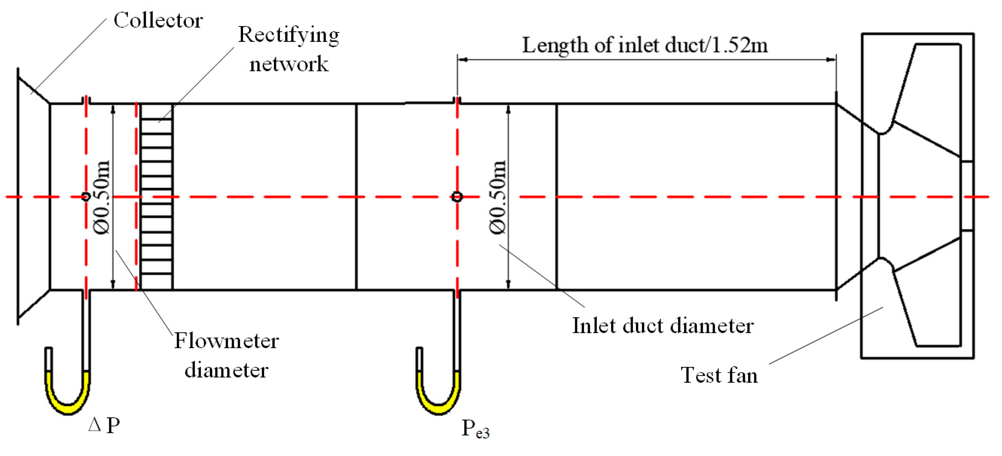
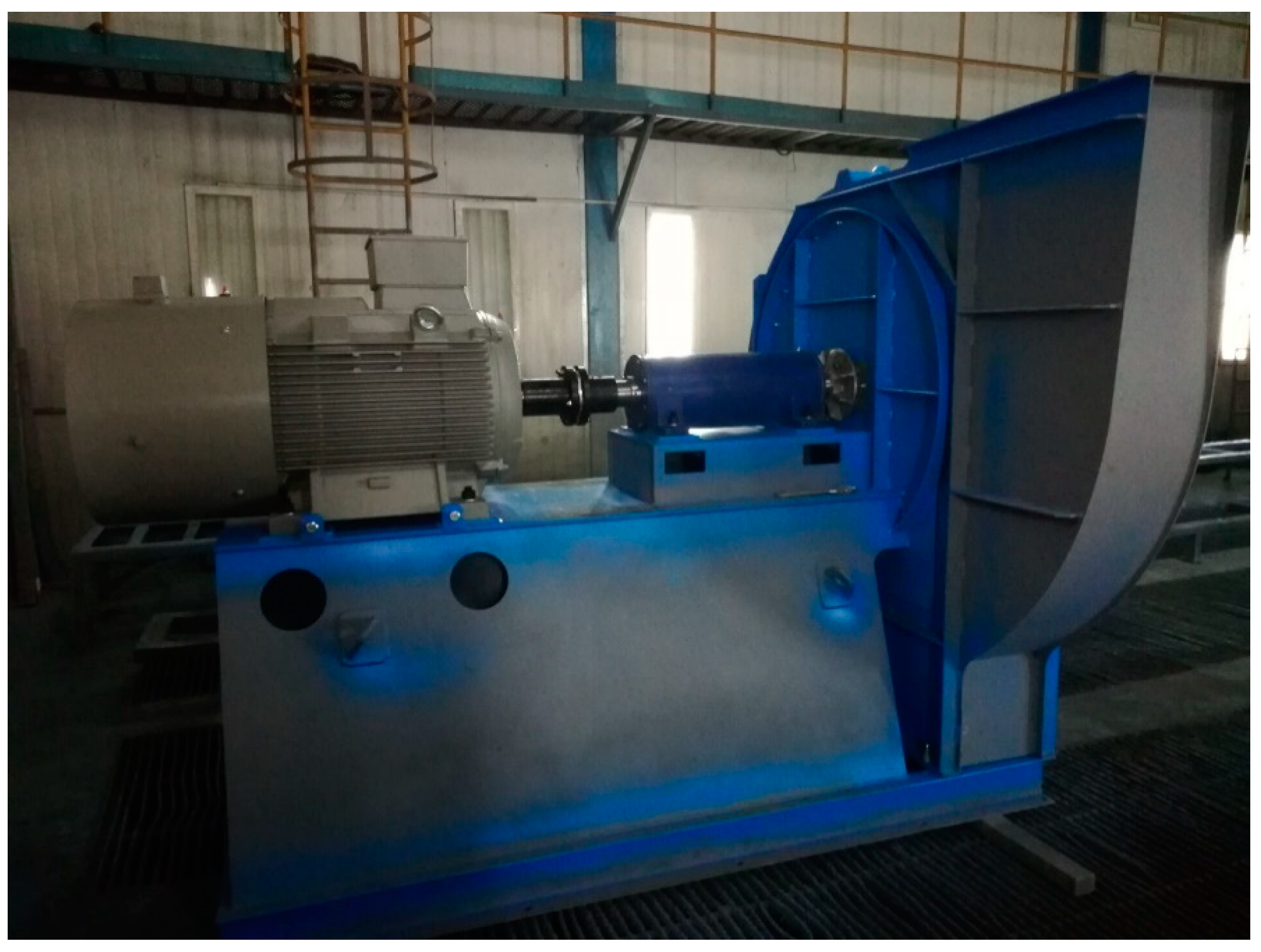
3.1. Experimental Equipment

To verify the feasibility of the established three-dimensional model of a centrifugal fan in numerical simulation, the external characteristics experiment of the fan model was carried out. The fan test was conducted according to the GB / T1236–2000 standard, the air intake test system was adopted, and the test device was type C (pipe inlet and free outlet) specified by the national standard. The schematic diagram of the experimental device is shown in Figure 4.
The centrifugal fan test platform was primarily composed of the fan inlet pipe, main body of the centrifugal fan, and motor. Among them, the inlet pipe part mainly included the current collector, compensation micromanometer, rectifier network, and U-tube liquid pressure gauge. Table 4 shows the instrument used in the test and its specific parameters. The actual drawing of the fan is shown in Figure 5, and Figure 1 shows the geometric model of Figure 5.

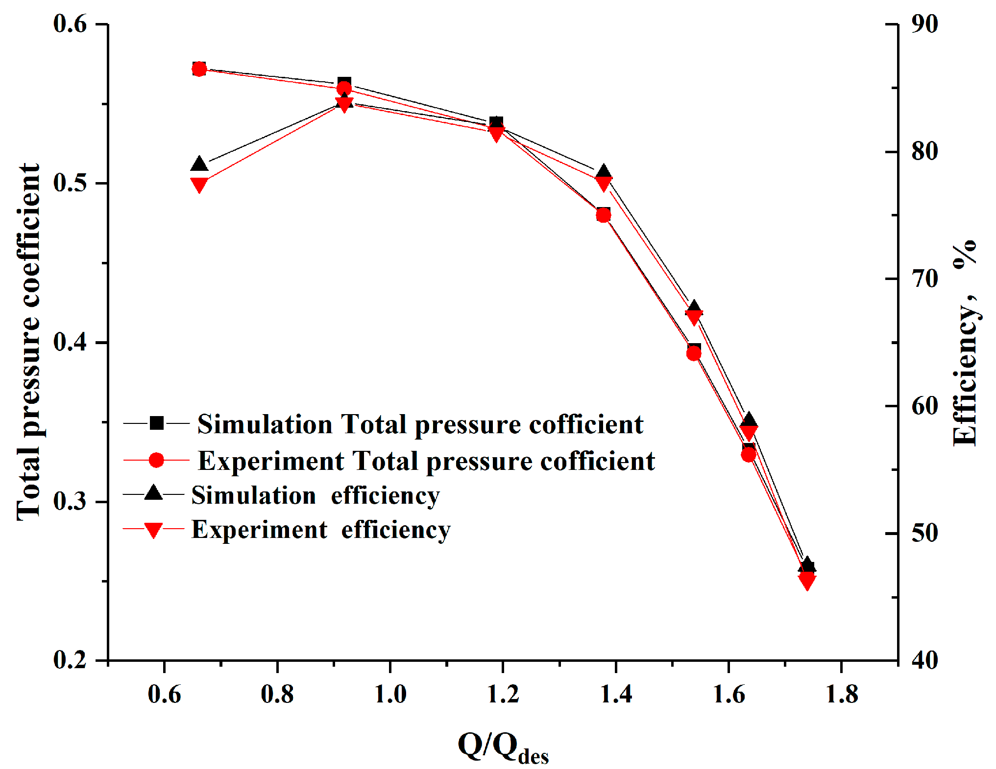
3.2. Experimental Results

Figure 6 shows the results comparison between the numerical simulation and experiment. The longitudinal coordinate is the total pressure coefficient P ¯ and total pressure efficiency η , and the calculation equation is expressed as:
P ¯ = P ρ u 2 ,
u = π D 2 n 60 ,
η = Q P M ω ,
where P , ρ , u , n , Q , M and ω respectively represent the total pressure, Pa; air density, kg/m3; impeller outlet diameter, mm; rotational speed, r/min; experimental flow rate m3/s; torque, N∙m; angular velocity, rad/s.
From Figure 6, the experiment results are close to the numerical results. Q/Qdes is the ratio of the experimental flow rate to the design flow rate. As the numerical simulation simplifies the model and neglects the loss, the simulation value was higher than the experimental value. The error between the tested and calculated total pressure was the smallest near the work point but gradually increased with the flow away from the design point, and the maximum deviation value did not exceed 8%.
There were two main influencing factors: One was the complex internal flow rule of fans under a small flow rate; the turbulence model selected in this paper could not effectively simulate the flow separation in the flow channel due to time and condition limitations. The other factor was that the actual flow rate of the fan was transient, which is ignored by the frozen rotor method. Although there were some errors between the experimental and the numerical results, the general changing trend of the total pressure and efficiency curves was the same, and the reliability of the numerical simulation can be confirmed according to the experimental results.

4. Results and Discussion

4.1. Contrast of External Characteristics

From Figure 7, the total pressure of the fan decreased with the increase of the flow rate. The efficiency of the fan increased first and then decreased, and it reached the highest value near the rated operating point. At Q/Qdes < 1.4, the total pressure of the fan increased first and then decreased with the rise of the blade outlet angle at the same flow rate. When β2 = 29.5°, the total pressure was the highest. In addition, the change trend of efficiency was different from the total pressure change. The outlet angle of the blade with the highest efficiency was different under different flow rates. At a high flow rate, the efficiency increased with the increase of the outlet angle. At the design or a low flow rate, the efficiency was the highest when the blade outlet angle was 26.5° and reached the maximum of 84.85% at the designed flow rate.

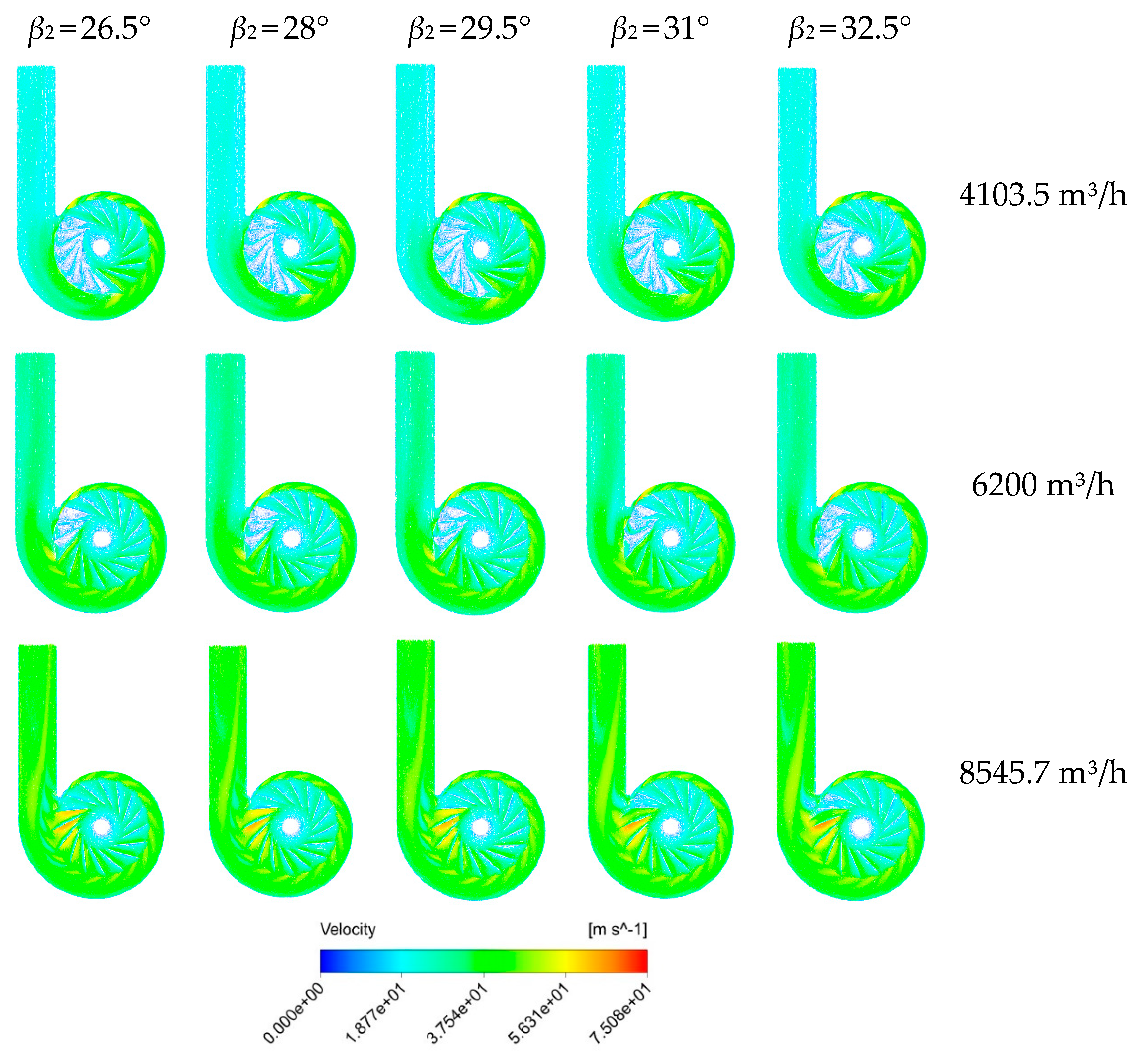
4.2. Velocity Vector Distribution

To further describe the internal flow of the fan, the relative velocity distributions in the middle section of the flow passage were obtained, as shown in Figure 8. There were vortices of different degrees in the impeller channel between 90° and 270° (see Figure 3) at different flow rates, and the number of vortices gradually decreased with the increase of the flow rate. At a low flow rate, the outlet angle had little effect on the relative velocity distribution; however, the velocity near the volute tongue increased significantly with the increase of the outlet angle.
At the design flow rate, when the blade outlet angle was 31°, the number of impeller channels with a vortex was the least, and the low-speed area of the impeller outlet was the least. Under the condition of a large flow rate, there were low-speed regions of varying degrees near the impeller outlet between 90° and 270°, and the area of the low-speed area decreased with the increase of the blade outlet angle. However, the flow state of the impeller channel near the volute tongue became increasingly unstable. When β2 = 32.5°, the low velocity region and flow separation appeared on the suction surface of the trailing edge of the blade, resulting in flow blockage. It may be that the outlet angle was too large to match the volute and that the fluid impact on the volute tongue caused this phenomenon.

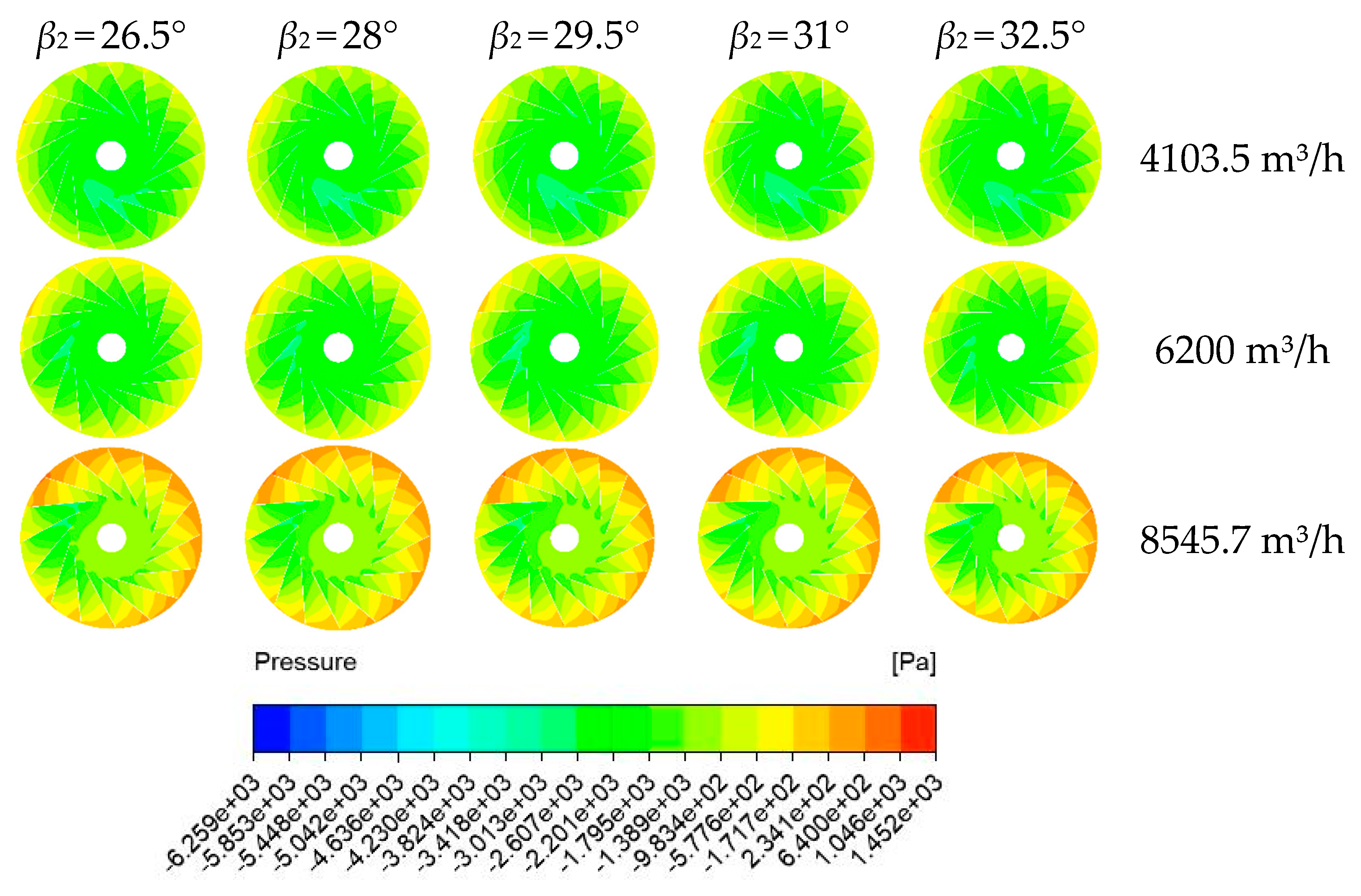
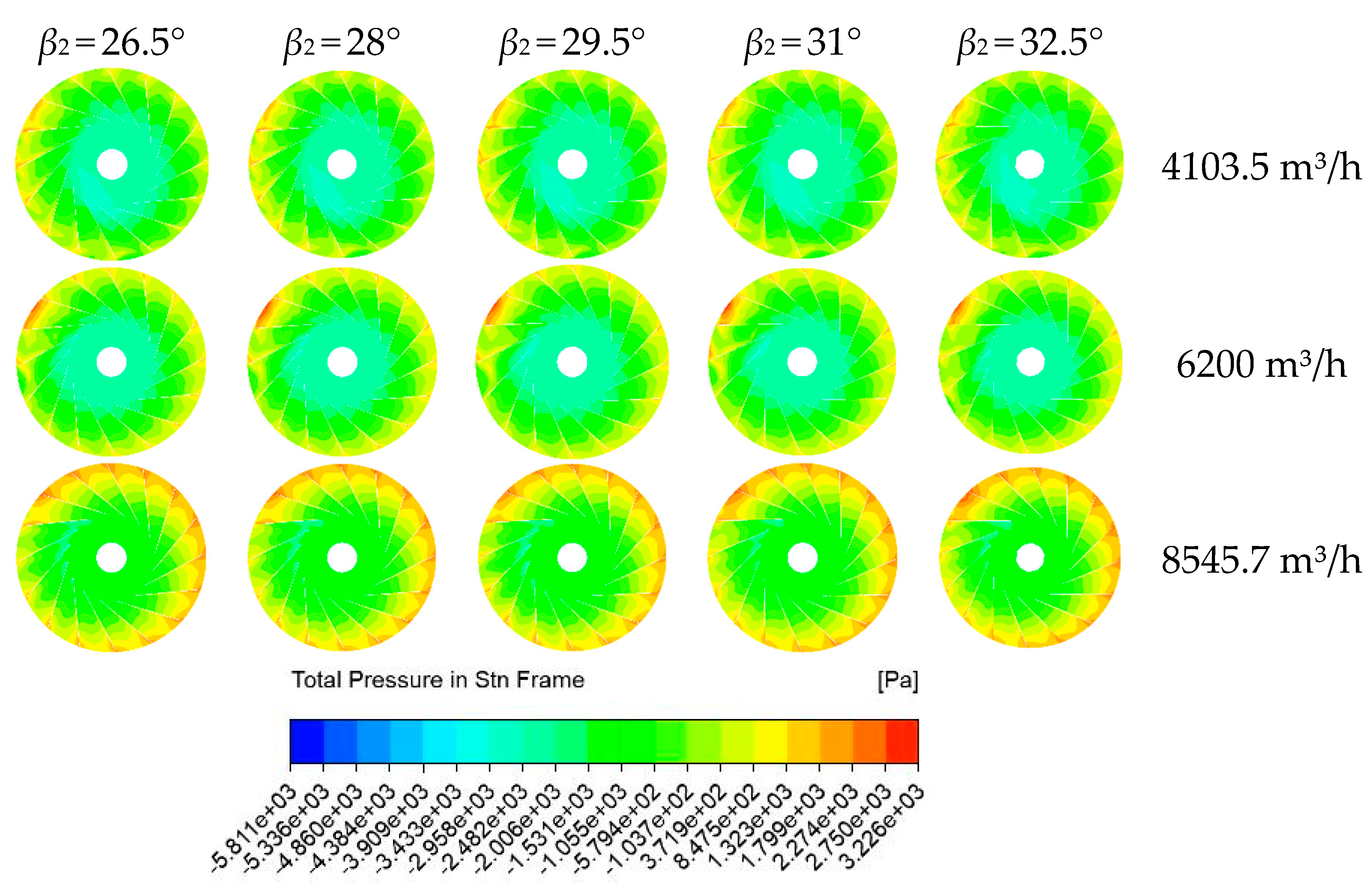
4.3. Pressure Distribution

Figure 9 shows the static pressure distribution of the middle span plane of impellers with different blade outlet angles and different flow rates. Under the condition of a low flow rate, the low-pressure region of the impeller inlet increased first and then decreased with the increase of the outlet angle. At the design flow rate, the area of the low-pressure zone increased first and then decreased with the increase of the impeller outlet angle between 90° and 270°. Under a large flow rate, there was a reverse pressure gradient in the impeller channel between 90° and 270°, and this phenomenon was alleviated with the increase of the blade outlet angle.
The static pressure increased with the increase of the flow rate. The maximum static pressure occurred at the impeller outlet near the volute tongue, which increased with the increase of the blade outlet angle, and the area of high pressure area became larger. In the static pressure distribution diagram of the impeller, we observed that the static pressure value of the fan gradually increased due to the continuous work of the impeller blade rotation on the air flow. At the impeller inlet, there was a clear low pressure area on the suction surface of the blade, and reverse flow occurred near the wall, resulting in separation loss. At high flow rates, this phenomenon was alleviated with the increase of the outlet angle.
As can be seen from Figure 10, the total pressure distribution of the fan gradually increased from the impeller inlet to the outlet. As the flow rate increased, the total pressure increased. Under different outlet angles, the pressure changes in the impeller passage mainly occurred between 90° and 270°. At a low flow rate, the total pressure did not change greatly with the increase of the blade outlet angle. At the design flow rate, the low-pressure region appeared at the outlet of the single impeller, which increased first and then decreased with the increase of the outlet angle.
Combined with the velocity vector diagram, the low-pressure area appeared in the low speed region. At high flow rates, the total pressure increased with the increasing of the outlet angle. With the increase of the blade outlet angle, the effective working area of the impeller increased, the total impeller pressure increased overall, especially in the circumferential area of the outlet of the blade. In addition, the pressure distribution of different flow paths between blades was different in the range of 90°−270°, which indicates that the flow characteristics inside the fan were asymmetric.

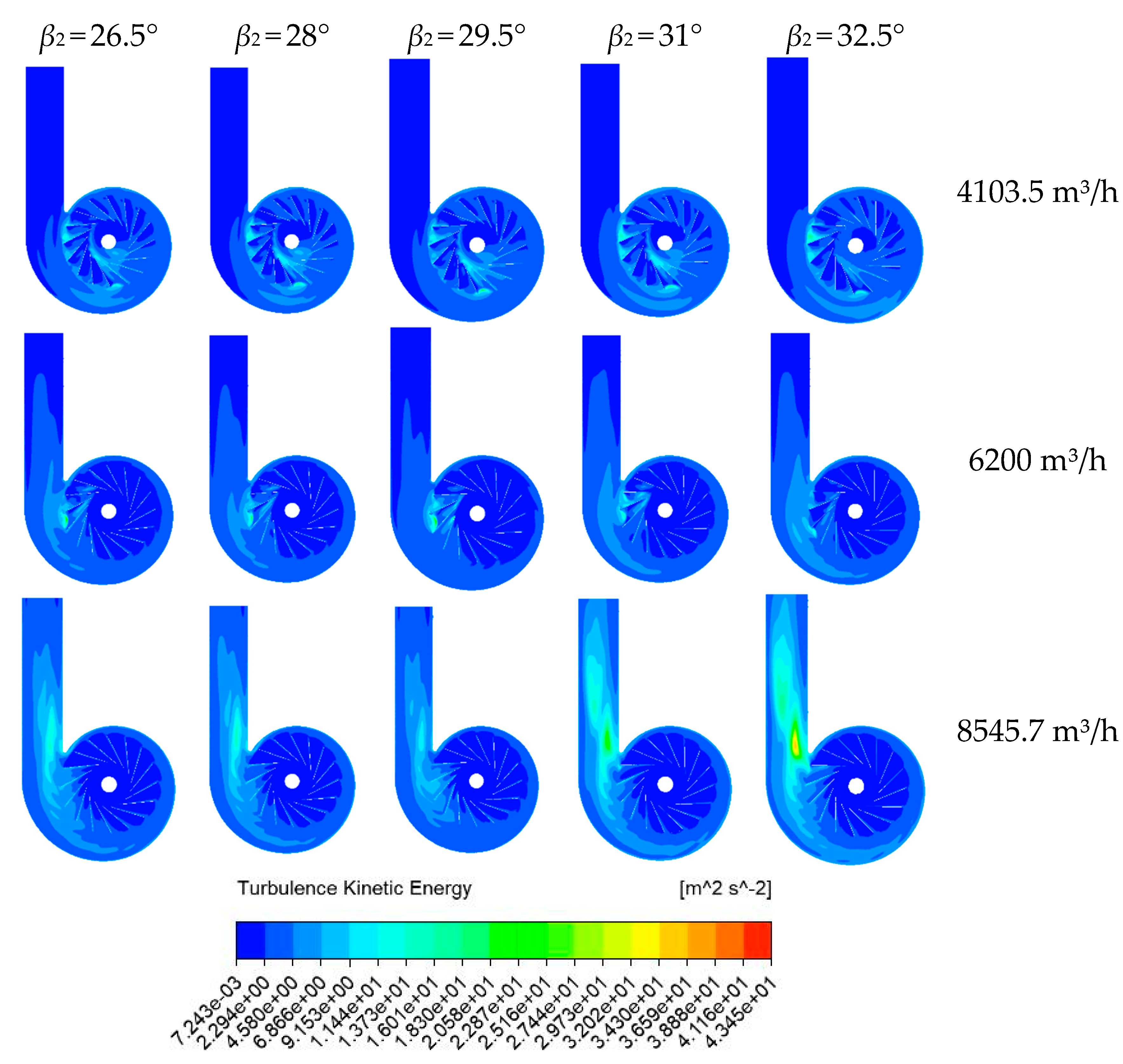
4.4. Turbulence Kinetic Energy Distribution

It can be seen from Figure 11 that the high turbulent kinetic energy region was mainly distributed near the volute tongue at the impeller outlet and gradually diffused toward the surrounding area. When the gas flowed through this area, boundary layer separation easily occurred. In general, the turbulent energy was the smallest when the blade outlet angle was 29.5°. With the increase of the blade outlet angle, the turbulent energy of the volute section first decreased and then increased. The outlet angle of the blade had a suitable value, which can reduce the flow loss of the volute section and improve the efficiency of the fan.

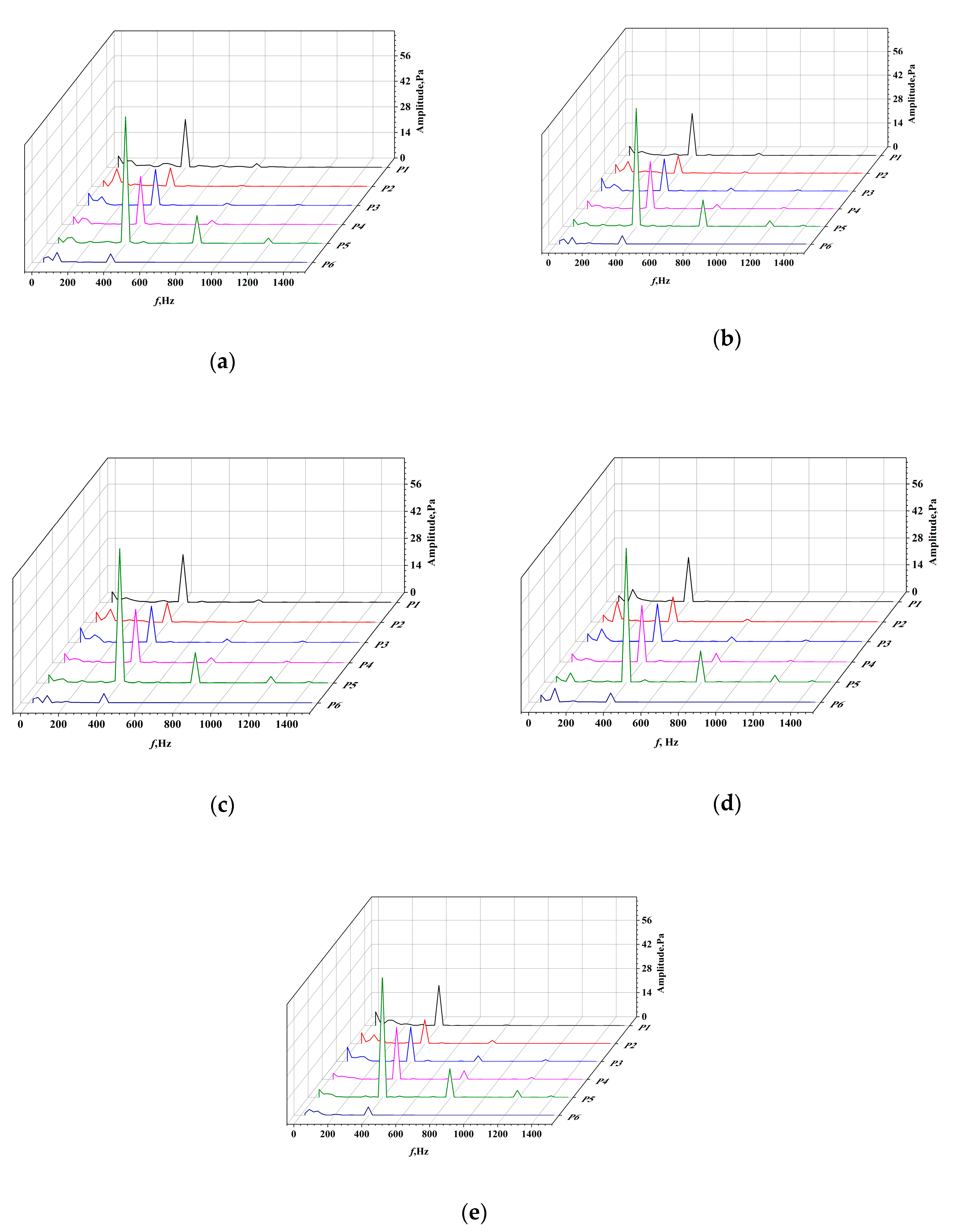
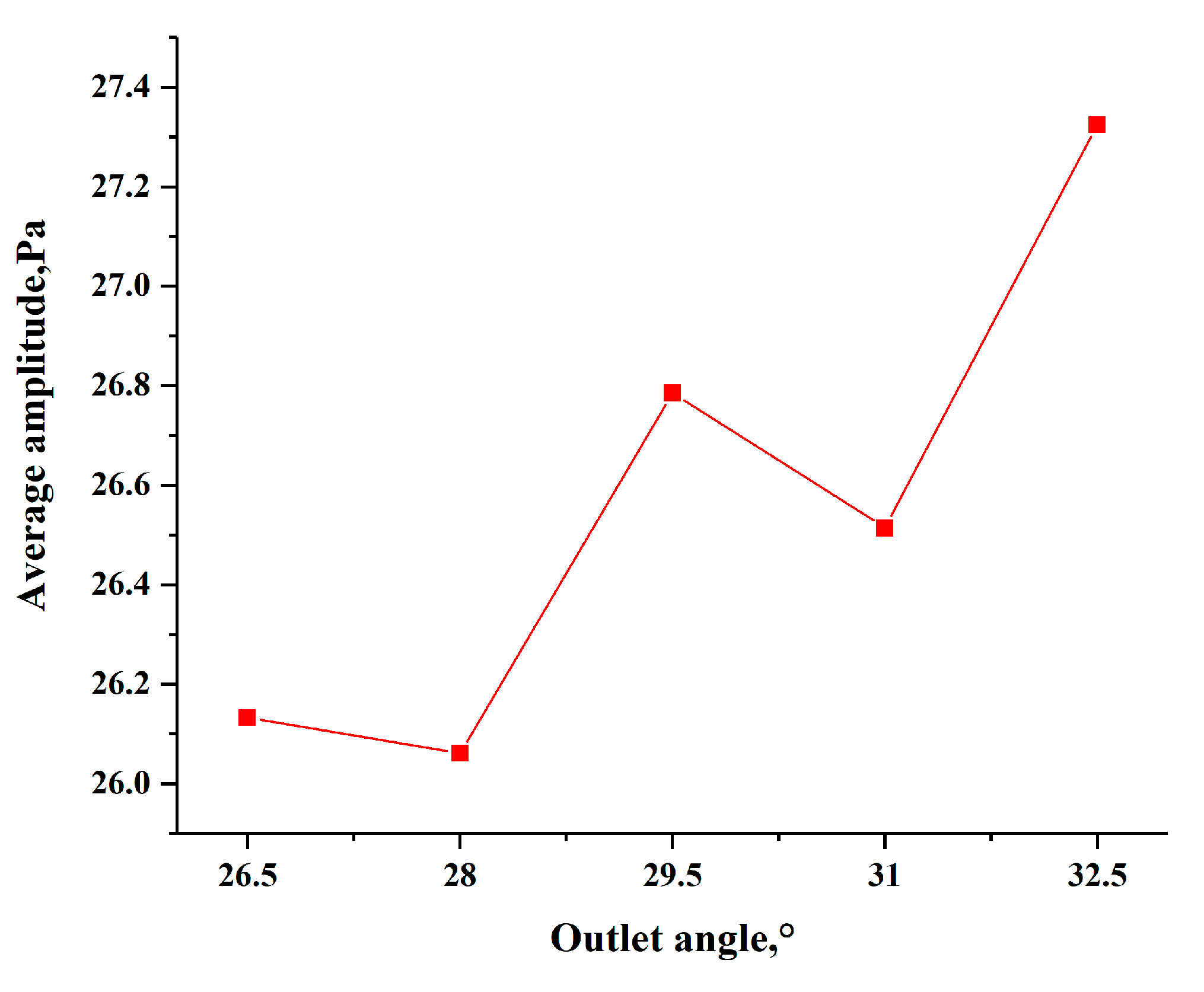
4.5. Pressure Pulsation Analysis

To better analyze the influence of the blade outlet angle on the pressure pulsation in the impeller outlet area, the time-domain characteristics of pressure pulsation at each monitoring point of the impeller were transformed by fast Fourier transform, and the frequency domain of pressure pulsation was obtained, as shown in Figure 12. It can be seen from the diagram that the main frequency of pulsation at the monitoring point of the impeller outlet of the centrifugal fan was the blade passing frequency (fBPF) and its frequency multiplication, and the amplitude of pulsation reached the maximum at the blade passing frequency. Due to rotor–stator interactions, pressure fluctuations near the volute tongue (P1, P5) were large. However, from the view of the frequency domain map of the monitoring points, the change rules of each monitoring point were different at different outlet angles, so further analysis is required. The blade passing frequency was calculated by Equation (4).
f BPF = N Z 60 ,
where N is the speed, r/min; Z is the number of blades.
For further analysis, we use mean pressure amplitude c p ¯ to calculate pressure pulsation energy of all the six measuring points for different outlet angles.
c p ¯ = 1 n c p i 6 ( n = 6 ) ,
where c p i represents the pressure amplitudes at f B E F for different measuring positions.
Figure 13 shows the average pressure amplitude at different outlet angles. In general, with the increase of the blade outlet angle, the pressure fluctuation amplitude of the fan increased. However, the amplitude of pressure fluctuation decreased with the increase of the blade outlet angle at 26.5°−28° and 29.5°−31°. Therefore, overall, the outlet angle of the blade increasing in a certain range reduced the pressure pulsation on the impeller, which is beneficial to reduce the noise of the impeller.

5. Conclusions

In this paper, five models of centrifugal fan impellers with different blade outlet angles were established, and the influence of the blade outlet angle on centrifugal fan performance was studied using CFD software. The conclusions can be drawn as follows:
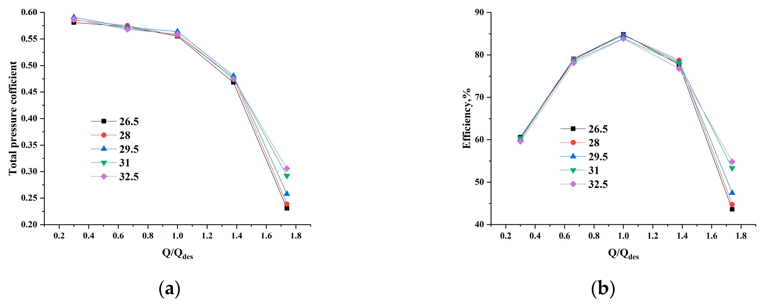
  • The blade outlet angle had different effects on the total pressure and efficiency. At Q/Qdes < 1.4, the total pressure coefficient of the fan first increased and then decreased with the rise of the blade outlet angle at the same flow rate. The outlet angle of the blade with the highest efficiency was different under different flow rates. At a high flow rate, the efficiency increased with the increase of the outlet angle. At the design or a low flow rate, the efficiency was the highest when the blade outlet angle was 26.5° and reached the maximum of 84.85% at the designed flow rate.
  • Through the simulation and analysis of the flow field inside a centrifugal fan, with the increase of the outlet angle, the flow speed near the volute tongue increased and the low pressure area at the impeller inlet first increased and then decreased at a low flow rate. With a blade outlet angle of 29.5° at the design flow rate, the swirl in the blade passage was minimal. In the case of a large flow rate, the increase of the blade outlet angle decreased the low speed area at the impeller outlet, decreased the reverse pressure gradient area at the blade leading edge, and increased the total pressure. The turbulent kinetic energy decreased first and then increased with the increase of the blade outlet angle.
  • Through the analysis of the frequency domain diagram, we found that the pressure fluctuation of a centrifugal fan was the smallest when the outlet angle of the blade was 28, and we found that properly increasing the outlet angle of the blade reduced the fluctuation amplitude of the fan at the blade frequency and its frequency multiplication, which is conducive to reducing impeller noise.

Author Contributions

Conceptualization, H.D.; Data curation, T.C.; Methodology, H.D. and T.C.; Software, F.L.; Supervision, H.D.; Validation, F.L.; Writing–original draft, T.C.; Writing–review and editing, H.D. All authors have read and agreed to the published version of the manuscript.

Funding

This research has been supported by key research and development project of Shandong province (2017GGX203005), Natural Science Foundation Project of Shandong province (ZR2019MEE068) and Design and performance optimization of magnetic levitation high speed centrifugal pump(201810424020). The supports are gratefully acknowledged.

Conflicts of Interest

The authors declare no conflict of interest.

References

  1. Chen, Y. Optimization of Aerodynamic Performance and Noise Control on a Forward Curved Centrifugal Fan. Master’s Thesis, Huazhong University of Science and Technology, Wuhan, China, 16 May 2016. [Google Scholar]
  2. Zhang, X.L.; Zhang, Y.L.; Lu, C.G. Flow and noise characteristics of centrifugal fan in low pressure environment. Processes 2020, 8, 985. [Google Scholar] [CrossRef]
  3. Zhou, B.; He, X.M.; Yang, H.; Zhu, Z.C.; Wei, Y.K.; Zhang, Y. Unsteady flow characteristics of rotating stall and surging in a backward centrifugal fan at low flow-rate conditions. Processes 2020, 8, 872. [Google Scholar] [CrossRef]
  4. Lin, S.C.; Tsai, M.L. An integrated performance analysis for a backward-inclined centrifugal fan. Comput. Fluids 2012, 56, 24–38. [Google Scholar] [CrossRef]
  5. Yu, S.B.; Li, J. Design of low-noise centrifugal fan for motorized spindle cooling system. Procedia Eng. 2011, 23, 380–386. [Google Scholar] [CrossRef] [Green Version]
  6. Kishokanna, P.; Srithar, R.; Alessandro, R.; Wira, J. Tonal noise prediction in a small high speed centrifugal fan and experimental validation. Appl. Acoust. 2017, 125, 29–70. [Google Scholar] [CrossRef]
  7. Li, X.; Wang, W.; Li, J.L.; Luo, X.Q.; Huang, Y.J. Analysis of the influence of different blade types on the performance of high specific speed centrifugal fan. In Proceedings of the Symposium on the development strategy of hydraulic machinery discipline and the 11th National Annual Conference on hydraulic machinery and its systems, Beijing, China, 19–21 October 2018. [Google Scholar]
  8. Wu, R.L.; Wu, P.J.; Qin, G.L. Numerical research on the effect of blade profile on performance of centrifugal fan. Compress. Blower Fan Technol. 2014, 0, 31–36. [Google Scholar] [CrossRef]
  9. Jian, X.S.; Chen., Q.; Sai, Q.Y.; Wu, H.Y.; Zhu, Z.N. Effect of the blade outlet width on the performance of small high speed backward curved centrifugal fans. Compress. Blower Fan Technol. 2017, 59, 71–76. [Google Scholar] [CrossRef]
  10. Liu, D.; Li, J.; Ling, X. Performance improvement of MVR high pressure centrifugal fan with designed number and outlet diameter of blades. fluid machinery. 2018, 046, 44–48. [Google Scholar] [CrossRef]
  11. Esra, S.; Yılmaz, D. Acoustic optimization for centrifugal fans. Noise Control Eng. J. 2012, 60, 379–390. [Google Scholar] [CrossRef]
  12. Meng, F.N.; Dong, Q.L.; Wang, Y.; Wang, P.F.; Zhang, C.X. Numerical optimization of impeller for backward-curved centrifugal fan by response surface methodology (RSM). Res. J. Appl. Sci. Eng. Technol. 2013, 6, 2436–2442. [Google Scholar] [CrossRef]
  13. Shi, Y.J.; Ge, A.X.; Fu, Y.X.; Wang, X. Retrofit analysis of the impeller and guide vanes of a centrifugal fan based on CFD. Compress. Blower Fan Technol. 2017, 59, 27–31. [Google Scholar] [CrossRef]
  14. Heo, M.W.; Kim, J.H.; Kim, K.Y. Design optimization of a centrifugal fan with splitter blades. Int. J. Turbo Jet Engines 2015, 32, 143–154. [Google Scholar] [CrossRef]
  15. Wang, X.; Sai, Q.Y. Multi-factor optimization and design of centrifugal fan based on orthogonal experiment method. Energy Eng. 2020, 4, 13–18. [Google Scholar] [CrossRef]
  16. Swe, W.W.M.; Morimatsu, H.; Hayashi, H.; Okumura, T.; Oda, I. Study of unsteady flow simulation of backward impeller with non-uniform casing. J. Therm. Sci. 2017, 26, 208–213. [Google Scholar] [CrossRef]
  17. Yu, S.Q.; Wu, D.Z.; Yang, S. Numerical study on the influence of blade outlet angle on the performance of multi-blade centrifugal fan. Fluid Mach. 2019, 47, 1–7. [Google Scholar] [CrossRef]
Figure 1. Geometric model of the original fan.
Processes 08 01422 g001
Figure 2. Mesh generation of the impeller and volute. (a) Impeller. (b) Volute. (c) Local refinements.
Processes 08 01422 g002
Figure 3. Schematic: (a) mid-section (z = 79 mm); (b) location of the monitoring point.
Processes 08 01422 g003
Figure 4. Schematic diagram of centrifugal fan experimental device.
Processes 08 01422 g004
Figure 5. The actual drawing of the fan.
Processes 08 01422 g005
Figure 6. Curve of the total pressure coefficient and efficiency of the centrifugal fan model.
Processes 08 01422 g006
Figure 7. External characteristic curve of fan with different blade outlet angles: (a) Comparison of the total pressure coefficient. (b) Efficiency comparison.
Processes 08 01422 g007
Figure 8. Velocity vector distributions at the middle span plane of the fan.
Processes 08 01422 g008
Figure 9. Static pressure distributions at the middle span plane of the impeller.
Processes 08 01422 g009
Figure 10. Total pressure distributions at the middle span plane of the impeller.
Processes 08 01422 g010
Figure 11. Turbulence kinetic energy distributions at the middle span plane of a fan.
Processes 08 01422 g011
Figure 12. Frequency domain of the pressure pulsation for different blade outlet angles: (a) 26.5°; (b) 28°; (c) 29.5°; (d) 31°; and (e) 32.5°.
Processes 08 01422 g012
Figure 13. Average pressure amplitude at different angles.
Processes 08 01422 g013
Table 1. Main design parameters of the centrifugal fan.
ParametersValues
Rated air flow6200 m³/h
Rated total pressure2700 Pa
Rated power30 kW
Rated speed1490 r/min
Table 2. Specific parameters of model fan impeller.
Parameters/MarksValue
Impeller outer diameter D2810 mm
Number of blades Z16
Impeller inner diameter D1368 mm
Blade outlet width b243 mm
Blade outlet angle β229.5°
Blade thickness δ3 mm
Table 3. Scheme for grid independence check.
No.Number of GridsTotal Pressure (Pa)Efficiency
I1,325,6012820.90.849
II2,578,4522686.60.838
III3,284,5612608.40.831
IV4,002,5632606.50.828
V4,951,2362606.90.830
Table 4. Instruments for the experiment.
Test Parameter NameInstrument NameModel/SpecificationMinimum ScaleAccuracy
Atmospheric pressureAneroid barometerYM3100 Pa≤200 Pa
Atmospheric temperaturehygrothermographTA2980.1 °C±1 °C
Atmospheric humidityhygrothermographTA2980.10%±5.0%
Flowmeter differential pressure/ΔPCompensation micromanometerYJB−25000.01 mm±8Pa
Gauge pressure/Pe3U-tube liquid pressure gauge 1 mm±0.5%
Test speedTorque meter100 N · m 0.1 r/min±0.1%
Shaft power0.1 kW
Torque0.1 N · m
Publisher’s Note: MDPI stays neutral with regard to jurisdictional claims in published maps and institutional affiliations.

