Effect of Rotor Spacing and Duct Diffusion Angle on the Aerodynamic Performances of a Counter-Rotating Ducted Fan in Hover Mode


Abstract
:1. Introduction
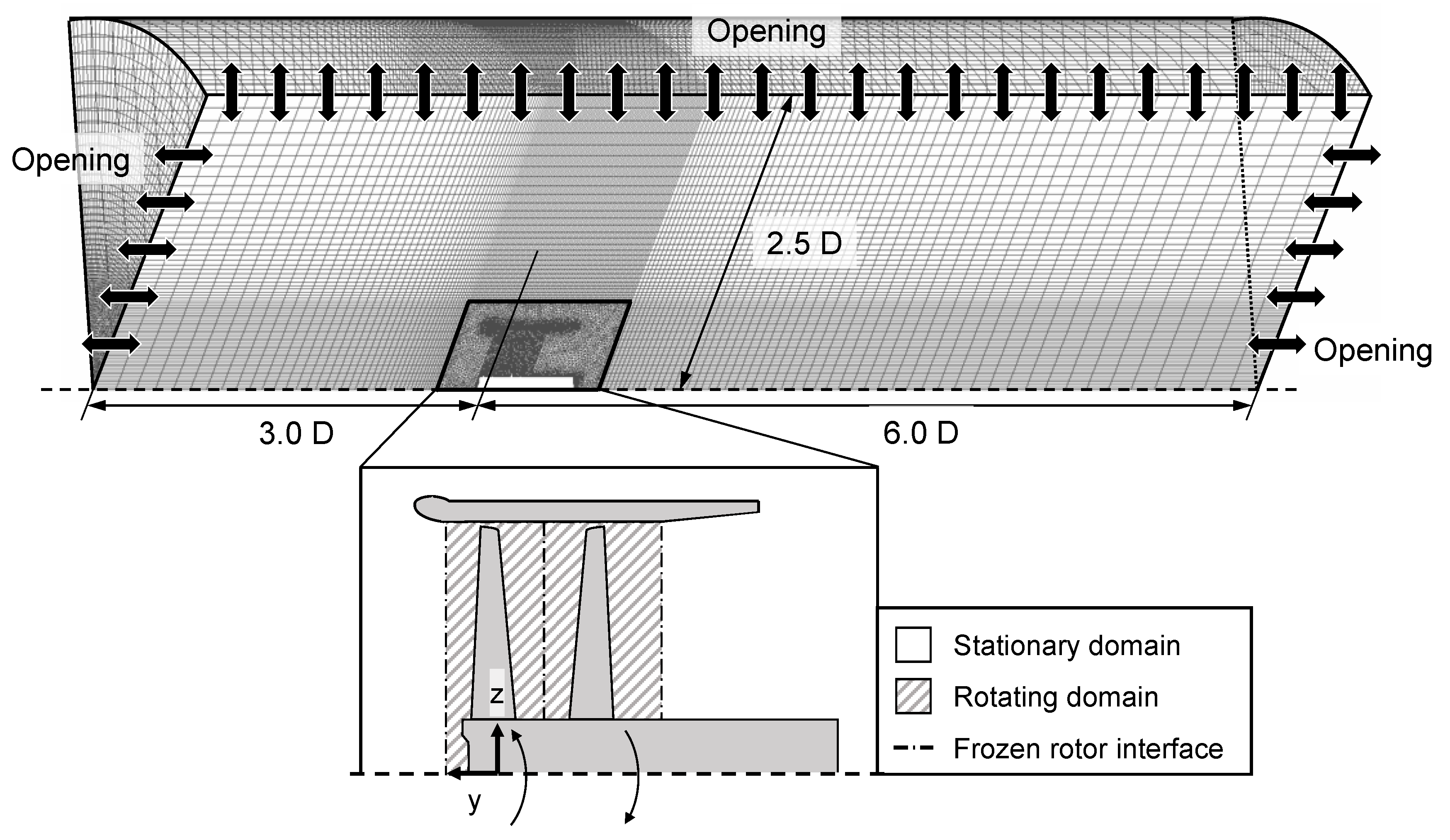
2. Numerical Model
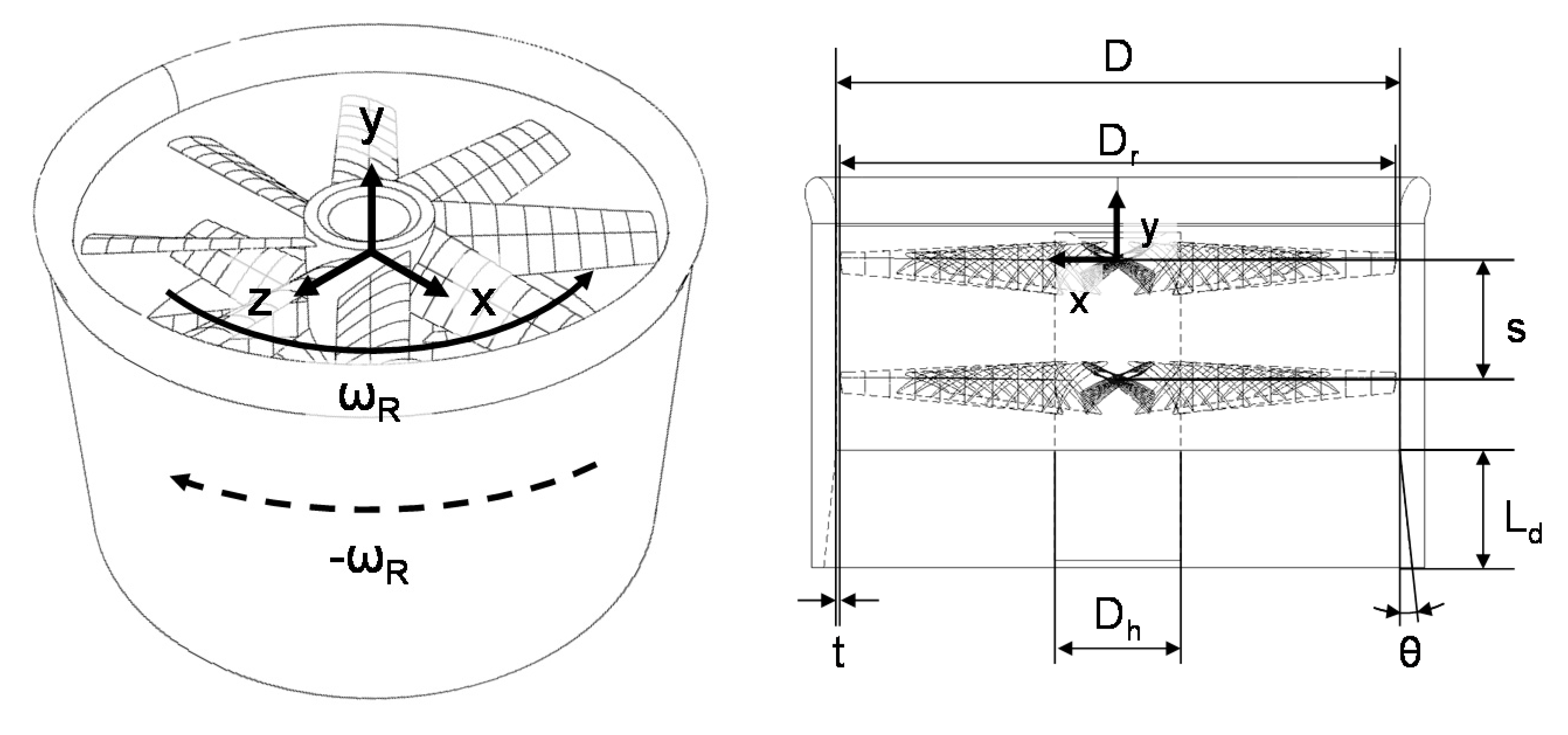
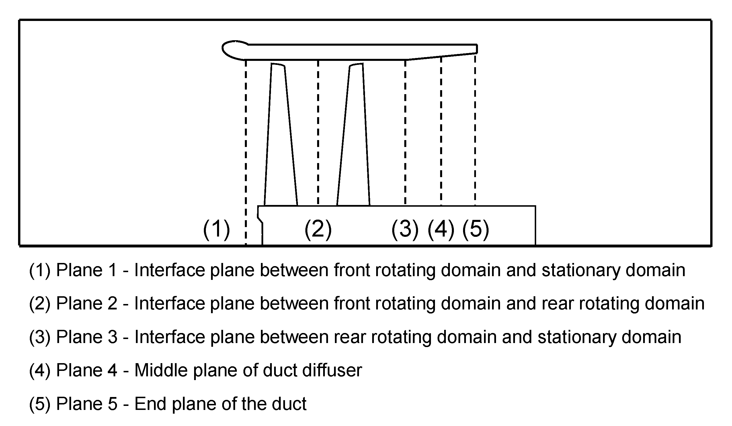
2.1. Model Description
2.2. Governing Equation
2.3. Numerical Method
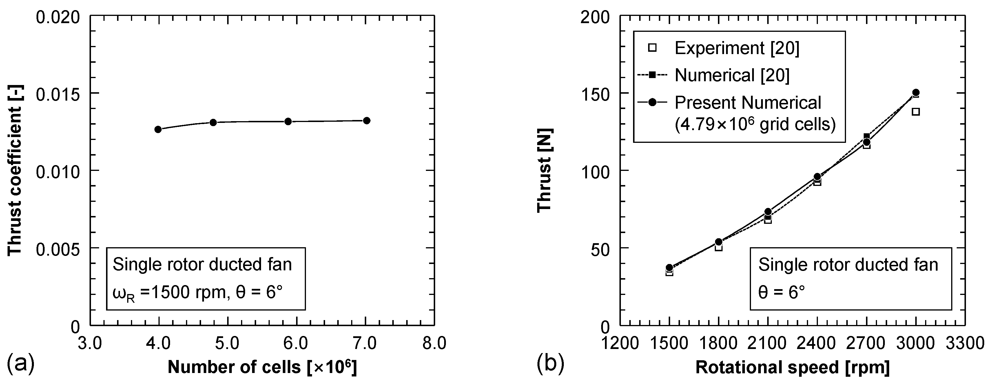
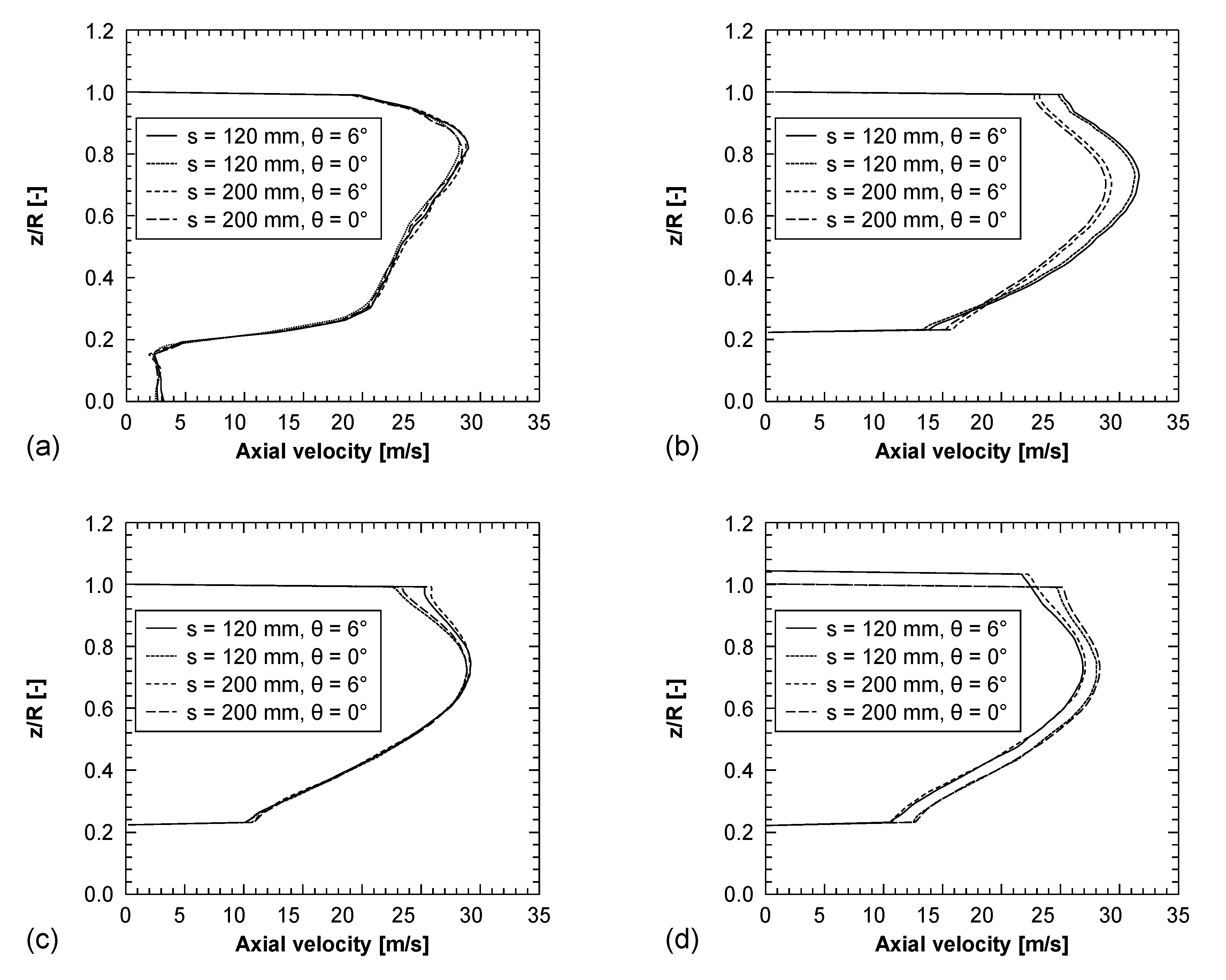
2.4. Grid Independence Test and Validation
3. Results and Discussion
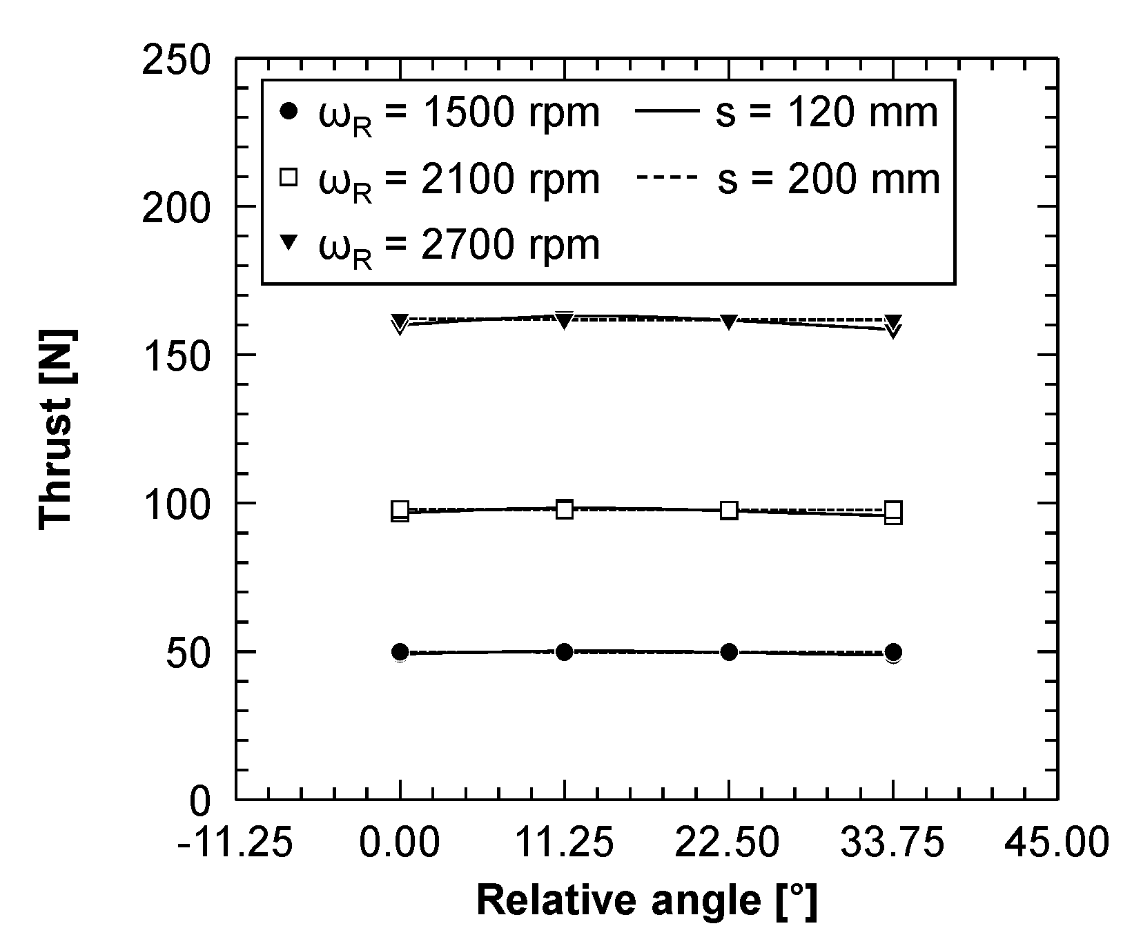
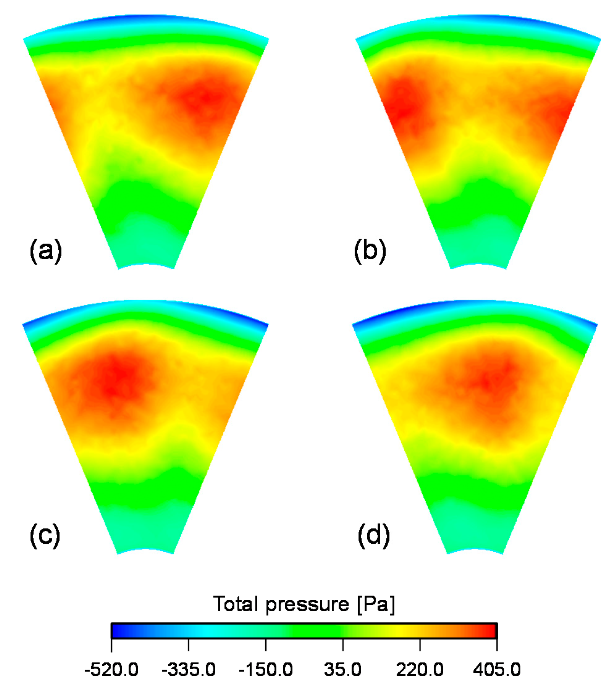
3.1. Effect of Relative Angle between Front and Rear Rotor
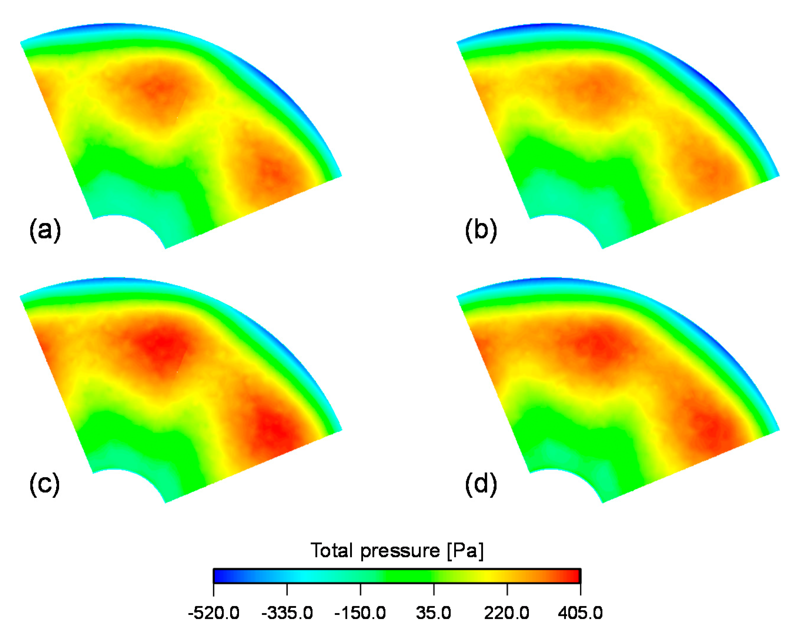
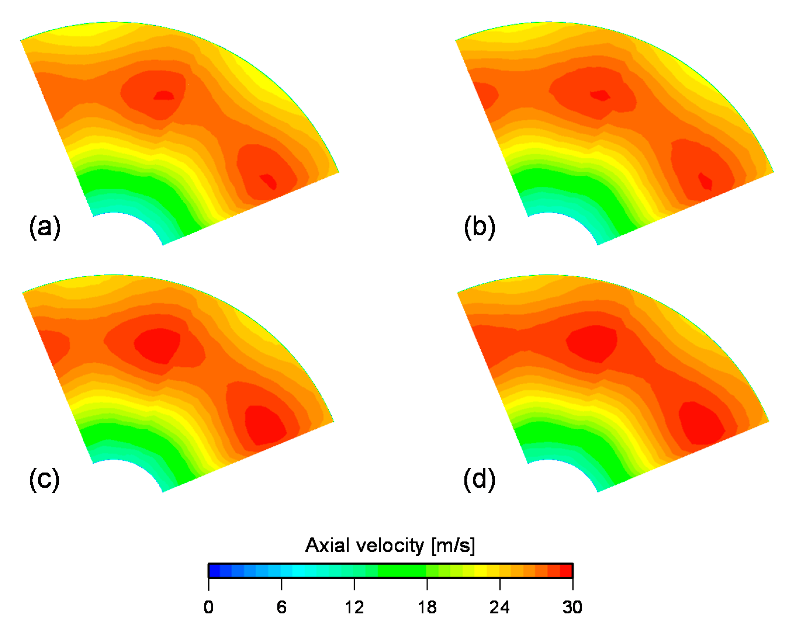
3.2. Aerodynamic Performance Analysis of Counter-Rotating Ducted Fan
4. Conclusions
- The effect of the relative angle between the front and the rear rotor, due to the usage of the frozen rotor model, is negligible since the variation of thrust for the different relative angles is extremely low.
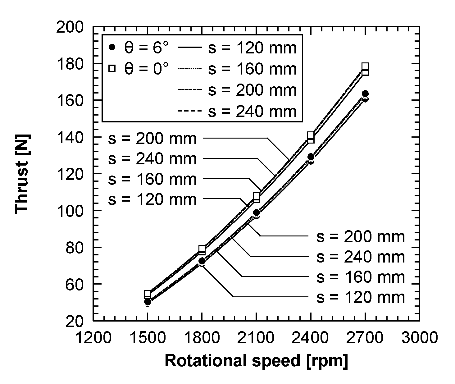
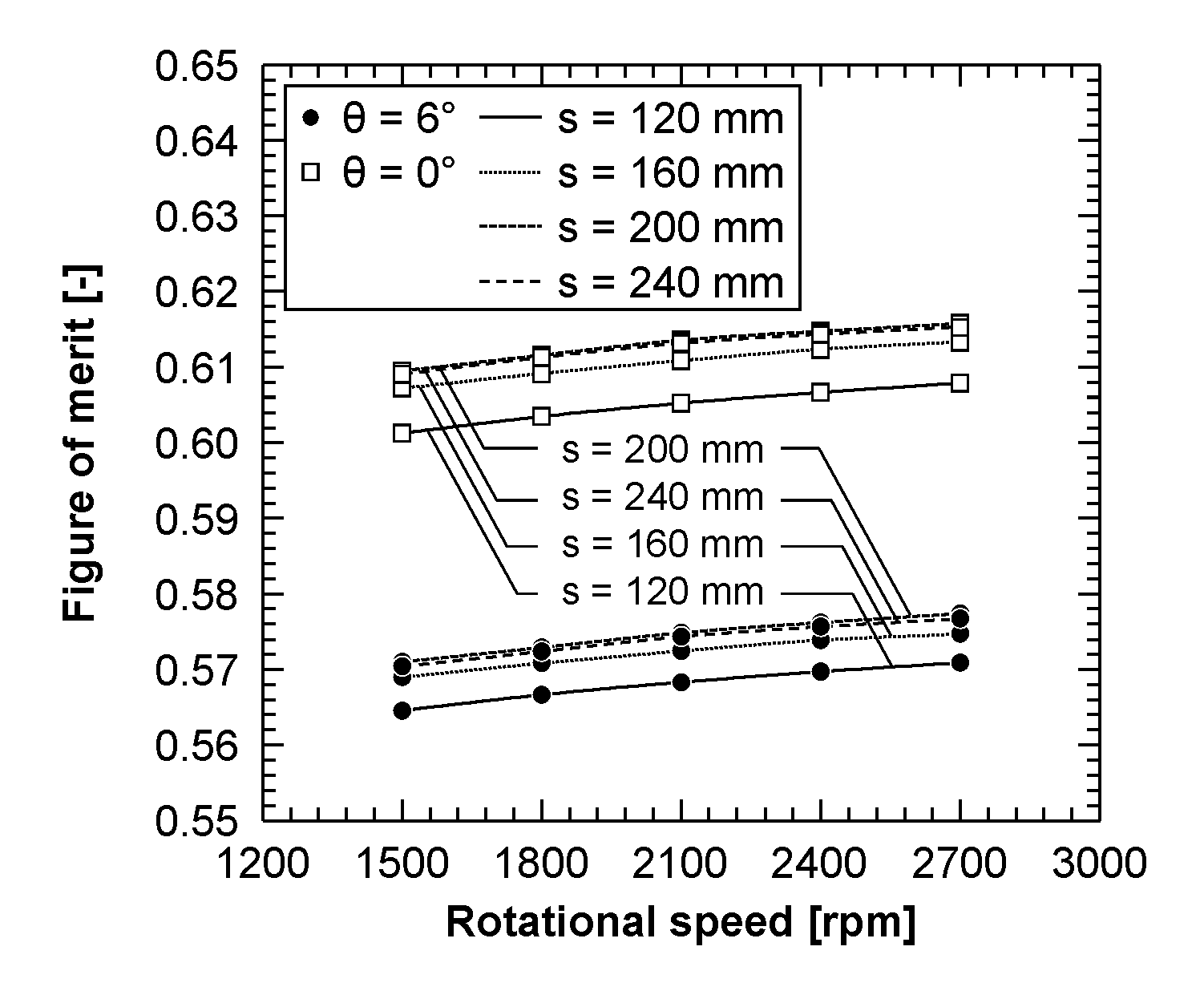
- Comparison of the aerodynamic performance parameters for different rotor spacings revealed that the thrust, thrust coefficient, and FOM slightly increases with an increasing rotor spacing up to 200 mm, regardless of the duct diffusion angle. However, the thrust, thrust coefficient, and FOM start to reduce on further increases in the rotor spacing. Conversely, the power coefficient is at a minimum when the rotor spacing is 120 mm.
- The maximum thrust coefficient is observed when the rotor spacing is 200 mm, and the thrust of the 200 mm rotor spacing increases by about 1.3–1.5% compared with the 120 mm rotor spacing.
- The duct diffusion angle of 0° generates about 9% higher thrust and increases the FOM by 6.7%, compared with the 6° duct diffusion angle.
- However, the increase in thrust also increases the power coefficient, which results in increased power consumption. The minimum power coefficient is attained for a 6° diffusion angle.
- The duct diffusion angle is highly effective in improving the thrust and FOM of the counter-rotating ducted fan, rather than the rotor spacing.
5. Future Work
Author Contributions
Funding
Conflicts of Interest
References
- Newman, S. Foundations of Helicopter Flight, 1st ed.; Elsevier: Amsterdam, The Netherlands, 1994. [Google Scholar]
- Thwaites, B. Incompressible Aerodynamics, 1st ed.; Oxford University Press: Oxford, UK, 1960. [Google Scholar]
- Yilmaz, S.; Erdem, D.; Kavsaoglu, M.S. Performance of a ducted propeller designed for UAV applications at zero angle of attack flight: An experimental study. Aerosp. Sci. Technol. 2015, 45, 376–386. [Google Scholar] [CrossRef]
- Bontempo, R.; Manna, M. Effects of Duct Cross Section Camber and Thickness on the Performance of Ducted Propulsion Systems for Aeronautical Applications. Int. J. Aerosp. Eng. 2016, 2016, 9. [Google Scholar] [CrossRef]
- Xu, H.Y.; Xing, S.L.; Ye, Z.Y. Numerical Study of Ducted-fan Lip Stall Suppression Based on Inflatable Leading Lip Cell. In Proceedings of the 7th International Conference on Fluid Mechanics, Shandong, China, 24–27 March 2015. [Google Scholar]
- Wernicke, K.G.; Wernicke, R.K.; Weisend, N.A., Jr. Inflatable wing leading edge for high lift and deicing. In NASA Tech Briefs; NASA: Washington, DC, USA, 2000; Volume 1. [Google Scholar]
- Jiang, Y.; Ye, Z.; Zhan, Z. A method of inflatable leading edge for high lift, deicing and noise reduction. In Proceedings of the 47th AIAA Aerospace Sciences Meeting including The New Horizons Forum and Aerospace Exposition, Orlando, FL, USA, 5–8 January 2009. [Google Scholar]
- Graf, W.; Fleming, J.; Ng, W. Improving ducted fan UAV aerodynamics in forward flight. In Proceedings of the 46th AIAA Aerospace Sciences Meeting and Exhibit, Reno, NE, USA, 7–10 January 2008. [Google Scholar]
- Jung, S.N.; No, T.S.; Ryu, K.W. Aerodynamic performance prediction of a 30 kW counter-rotating wind turbine system. Renew. Energy 2005, 30, 631–644. [Google Scholar] [CrossRef]
- Vasel-Be-Hagh, A.; Archer, C.L. Wind farms with counter-rotating wind turbines. Sustain. Energy Technol. Assess. 2017, 24, 19–30. [Google Scholar] [CrossRef]
- Furukawa, A.; Shigemitsu, T.; Watanabe, S. Performance test and flow measurement of contra-rotating axial flow pump. J. Therm. Sci. 2007, 16, 7–13. [Google Scholar] [CrossRef]
- Kim, J.H.; Cho, B.M.; Kim, S.; Kim, J.W.; Suh, J.W.; Choi, Y.S.; Kanemoto, T.; Kim, J.H. Design technique to improve the energy efficiency of a counter-rotating type pump-turbine. Renew. Energy 2017, 101, 647–659. [Google Scholar] [CrossRef]
- Shigemitsu, T.; Fukutomi, J.; Okabe, Y. Performance and flow condition of small-sized axial fan and adoption of contra-rotating rotors. J. Therm. Sci. 2010, 19, 1–6. [Google Scholar] [CrossRef]
- Toge, T.D.; Pradeep, A.M. Experimental investigation of stall inception of a low speed contra rotating axial flow fan under circumferential distorted flow condition. Aerosp. Sci. Technol. 2017, 70, 534–548. [Google Scholar] [CrossRef]
- Srivastava, R.; Sankar, L.N. Efficient hybrid scheme for the analysis of counter-rotating propellers. J. Propuls. Power 1993, 9, 382–388. [Google Scholar] [CrossRef]
- Brizzolara, S.; Tincani, E.P.A.; Grassi, D. Design of contra-rotating propellers for high-speed stern thrusters. Ships Offshore Struct. 2007, 2, 169–182. [Google Scholar] [CrossRef]
- Ryu, M.; Cho, L.; Cho, J. The effect of tip clearance on performance of a counter-rotating ducted fan in a VTOL UAV. Trans. Jpn. Soc. Aeronaut. Space Sci. 2017, 60, 1–9. [Google Scholar] [CrossRef] [Green Version]
- Han, H.; Xiang, C.; Xu, B.; Yu, Y. Experimental and computational analysis of microscale shrouded coaxial rotor in hover. In Proceedings of the 2017 International Conference on Unmanned Aircraft Systems, Miami, FL, USA, 13–16 June 2017. [Google Scholar]
- Corsini, A.; Delibra, G.; Sheard, A.G. A critical review of computational methods and their application in industrial fan design. ISRN Mech. Eng. 2013, 2013, 20. [Google Scholar] [CrossRef]
- Akturk, A.; Camci, C. Tip Clearance Investigation of a Ducted Fan Used in VTOL Unmanned Aerial Vehicles—Part I: Baseline Experiments and Computational Validation. J. Turbomach. 2014, 136, 021004. [Google Scholar] [CrossRef]
- Ansys CFX 19.1. Theory Guide 2018; ANSYS, Inc.: Canonsburg, PA, USA, 2018. [Google Scholar]
- Menter, F.R. Zonal two equation k-w turbulence models for aerodynamic flows. In Proceedings of the 24th Fluid Dynamics Conference, Orlando, FL, USA, 6–9 July 1993. [Google Scholar]
- Menter, F.R. Two-equation eddy-viscosity turbulence models for engineering applications. AIAA J. 1994, 32, 1598–1605. [Google Scholar] [CrossRef] [Green Version]
- Benim, A.C.; Brillert, D.; Cagan, M. Investigation Into the Computational Analysis of Direct-Transfer Pre-Swirl Systems for Gas Turbine Cooling. In Proceedings of the ASME Turbo Expo 2004: Power for Land, Sea, and Air, Vienna, Austria, 14–17 June 2004. [Google Scholar]
- Bohn, D.; Ausmeier, S.; Ren, J. Investigation of the Optimum Clocking Position in a Two-Stage Axial Turbine. Int. J. Rotating Mach. 2005, 3, 202–210. [Google Scholar] [CrossRef] [Green Version]
- Chalghoum, I.; Kanfoudi, H.; Elaoud, S.; Akrout, M.; Zgolli, R. Numerical Modeling of the Flow Inside a Centrifugal Pump: Influence of Impeller–Volute Interaction on Velocity and Pressure Fields. Arab. J. Sci. Eng. 2016, 41, 4463–4476. [Google Scholar] [CrossRef]


| Parameter | Value |
|---|---|
| Duct diameter, D | 559.0 mm |
| Rotor diameter, Dr | 558.8 mm |
| Tip clearance, t | 1.71% |
| Hub diameter, Dh | 127 mm |
| Length of the duct diffuser, Ld | 117.85 mm |
| Duct Diffusion Angle [°] | Rotor Spacing [mm] | Thrust [N] | ||||
|---|---|---|---|---|---|---|
| Rotating Speed [rpm] | ||||||
| 6 | 120 | 49.49 | 71.30 | 97.09 | 126.86 | 160.62 |
| 160 | 50.18 | 72.27 | 98.40 | 128.58 | 162.72 | |
| 200 | 50.38 | 72.56 | 98.84 | 129.15 | 163.52 | |
| 240 | 50.22 | 72.34 | 98.54 | 128.75 | 162.99 | |
| 0 | 120 | 53.96 | 77.76 | 105.90 | 138.38 | 175.21 |
| 160 | 54.78 | 78.93 | 107.49 | 140.46 | 177.80 | |
| 200 | 54.95 | 79.17 | 107.84 | 140.89 | 178.36 | |
| 240 | 54.81 | 78.98 | 107.58 | 140.55 | 177.91 | |
| Duct Diffusion Angle [°] | Rotor Spacing [mm] | Thrust Coefficient | ||||
| Rotating Speed [rpm] | ||||||
| 6 | 120 | 0.017335 | 0.017343 | 0.017350 | 0.017357 | 0.017364 |
| 160 | 0.017576 | 0.017579 | 0.017584 | 0.017592 | 0.017591 | |
| 200 | 0.017646 | 0.017650 | 0.017664 | 0.017671 | 0.017678 | |
| 240 | 0.017589 | 0.017595 | 0.017609 | 0.017616 | 0.017620 | |
| 0 | 120 | 0.018902 | 0.018914 | 0.018924 | 0.018933 | 0.018942 |
| 160 | 0.019193 | 0.019199 | 0.019208 | 0.019218 | 0.019221 | |
| 200 | 0.019247 | 0.019256 | 0.019272 | 0.019277 | 0.019281 | |
| 240 | 0.019199 | 0.019212 | 0.019226 | 0.019231 | 0.019234 | |
| Duct Diffusion Angle [°] | Rotor Spacing [mm] | Power Coefficient | ||||
| Rotating Speed [rpm] | ||||||
| 6 | 120 | 0.003112 | 0.003103 | 0.003096 | 0.003090 | 0.003085 |
| 160 | 0.003152 | 0.003143 | 0.003135 | 0.003130 | 0.003125 | |
| 200 | 0.003160 | 0.003151 | 0.003143 | 0.003138 | 0.003133 | |
| 240 | 0.003148 | 0.003139 | 0.003132 | 0.003126 | 0.003122 | |
| 0 | 120 | 0.003327 | 0.003318 | 0.003311 | 0.003305 | 0.003301 |
| 160 | 0.003371 | 0.003361 | 0.003354 | 0.003349 | 0.003344 | |
| 200 | 0.003372 | 0.003363 | 0.003356 | 0.003351 | 0.003347 | |
| 240 | 0.003362 | 0.003353 | 0.003347 | 0.003341 | 0.003337 | |
Publisher’s Note: MDPI stays neutral with regard to jurisdictional claims in published maps and institutional affiliations. |
© 2020 by the authors. Licensee MDPI, Basel, Switzerland. This article is an open access article distributed under the terms and conditions of the Creative Commons Attribution (CC BY) license (http://creativecommons.org/licenses/by/4.0/).
Share and Cite
Kim, W.-Y.; Senguttuvan, S.; Kim, S.-M. Effect of Rotor Spacing and Duct Diffusion Angle on the Aerodynamic Performances of a Counter-Rotating Ducted Fan in Hover Mode. Processes 2020, 8, 1338. https://doi.org/10.3390/pr8111338
Kim W-Y, Senguttuvan S, Kim S-M. Effect of Rotor Spacing and Duct Diffusion Angle on the Aerodynamic Performances of a Counter-Rotating Ducted Fan in Hover Mode. Processes. 2020; 8(11):1338. https://doi.org/10.3390/pr8111338
Chicago/Turabian StyleKim, Woo-Yul, Santhosh Senguttuvan, and Sung-Min Kim. 2020. "Effect of Rotor Spacing and Duct Diffusion Angle on the Aerodynamic Performances of a Counter-Rotating Ducted Fan in Hover Mode" Processes 8, no. 11: 1338. https://doi.org/10.3390/pr8111338