Article

Using PSO Algorithm to Compensate Power Loss Due to the Aeroelastic Effect of the Wind Turbine Blade

1
Institute of Engineering Thermophysics, Chinese Academy of Sciences, Beijing 100190, China
2
University of Chinese Academy of Sciences, Beijing 100190, China
3
Key Laboratory of Wind Energy Utilization, Chinese Academy of Sciences, Beijing 100190, China
4
National Laboratory of Wind Turbine Blade Research & Development Center, Beijing 100190, China
5
Dalian National Laboratory for Clean Energy, Chinese Academy of Sciences, Dalian 116023, China
*
Author to whom correspondence should be addressed.
Processes 2019, 7(9), 633; https://doi.org/10.3390/pr7090633
Submission received: 31 July 2019 / Revised: 11 September 2019 / Accepted: 12 September 2019 / Published: 18 September 2019

Abstract

:
Power loss due to the aeroelastic effect of the blade is becoming an important problem of large-scale blade design. Prior work has already employed the pretwisting method to deal with this problem and obtained some good results at reference wind speed. The aim of this study was to compensate for the power loss for all of the wind speeds by using the pretwisting method. Therefore, we developed an aeroelastic coupling optimization model, which takes the pretwist angles along the blade as free variables, the maximum AEP (annual energy production) as the optimal object, and the smooth of the twist distribution as one of the constraint conditions. In this optimization model, a PSO (particle swarm optimization) algorithm is used and combined with the BEM-3DFEM (blade element momentum—three-dimensional finite element method) model. Then, the optimization model was compared with an iteration method, which was recently developed by another study and can well compensate the power loss at reference wind speed. By a design test, we found that the power loss can be reduced by pretwisting the origin blade, whether using the optimization model or the iteration method. Moreover, the optimization model has better ability than the iteration method to compensate the power loss with lower thrust coefficient while keeping the twist distribution smooth.

1. Introduction

In modern times, in order to reduce environmental contamination and carbon emission, clean energy such as wind energy are quickly developing. To get more energy from wind energy, many researchers have done lots of works to improve the power output. These works include aerodynamic optimization [1,2], adding flow control devices like vortex generators (VGs) and gurney flaps (GFs) on the blade [3,4,5], control rules design [6,7] and so on. Besides, some researchers have even applied intelligent algorithms such as reinforcement learning (RL) [6] and evolutionary strategy algorithm [7] to increase aerodynamic performance. These studies are very useful for raising the ratio of wind energy utilization. However, power loss due to the aeroelastic effect is not dedicatedly studied.
Practically, with the increasing unit capacity of wind turbines, blades become longer and softer. Under the action of the different kinds of loads, especially aerodynamic forces, the flexible blade generates non-negligible deflections. These deflections, in turn, change the aerodynamic loads on the blade. Particularly, the induced twist due to the aeroelastic effect has a significant impact on the load and the power performance of the blade. Many researchers have studied the aeroelastic effect and found that an induced twist would not only reduce the blade load, but also decrease the power output [8,9,10,11,12]. This phenomenon is contrary to design objectives, one of which is to capture as much wind energy as possible. To deal with this problem, Lobitz et al. [9] suggested compensating the power loss by pretwisting the blade to adjust for coupling-induced twist. Lee et al. [11] also thought a pretwisting design of blade geometry could provide power performance superior to that of the origin blade after they found that the power loss was more than 13% in some wind speeds. Therefore, understanding how to obtain a suitable pretwist angle distribution along the blade is very important to output the maximum power. Recently, Stäblein et al. [8] presented an iteration procedure to get the pretwist angle distribution at specific wind speed. It can efficiently increase the power at the selected wind speed and make it close to the power without considering the aeroelastic effect. However, the power performances at many other wind speeds are not taken into account. In fact, the induced twist distribution changes with the operational state. This pretwist angle distribution calculated at one wind speed may not suitable for other wind speeds. Hence, it cannot get the maximum annual energy production (AEP), and it even reduces the AEP. Besides, the smooth of the blade profile, which makes the blade feasible in practical, has not been considered yet. Generally, the pretwist angle varies from the blade root to the blade tip. If the pretwist angle distribution is not restrained, after pretwisting the origin blade using these pretwist angles, the twist distribution of the blade will become out of control, and the blade may get an irregular aerodynamic profile.
Therefore, the aim of this study was to compensate for the power loss for all the wind speeds by using the pretwisting method. Firstly, an aeroelastic coupling optimization model, combining the PSO (particle swarm optimization) algorithm with the BEM-3DFEM (blade element momentum—three-dimensional finite element method) model, was built and verified. In this model, we considered the pretwist angle distribution as free variables, taking the maximum AEP (annual energy production) as the optimal object and the smooth of the twist distribution as one of the constraint conditions. Secondly, the optimization model was applied to a 100 kW wind turbine and compared with an iteration method [8], which was recently developed by another study and can well compensate the power loss at reference wind speed. Thirdly, we carried out some analysis and discussion about the results.

2. Aeroelastic Model

In this section, a steady-state aeroelastic coupling model, called the BEM-3DFEM (blade element momentum—three-dimensional finite element method) model, was developed to calculate the power output during the normal operating state.

2.1. Aerodynamic Model and Verification

There are many methods for calculating the aerodynamic performance of a wind turbine, such as the BEM (blade element momentum) method [13,14], the vortex model [14,15], and the CFD (computational fluid dynamics) model [15,16]. Among them, the BEM method is the most widely used, due to its superior comprehensive performance on the computation cost and simulation precision. In this paper, the BEM model, considering the tip loss and hub loss, was used to get the steady aerodynamic performance of the blade. This aerodynamic model was programmed by using the MATLAB language (Matlab R2012a, The MathWorks, Inc., Novi, MI, USA, 2012). To certificate this procedure, it was used to calculate the aerodynamic performance of the NREL (natioanal renewable energy laboratory) phase VI wind turbine (NREL, Golden, CO, USA) [17,18]. The results of this BEM procedure, compared with the experiment results and the results using GH Bladed software [19], are shown in Figure 1. As can be seen, the power coefficients and the powers from the above three methods are close. So, this BEM procedure can be used to evaluate the aerodynamic performance of the wind turbine blade.

2.2. Structure Model and Verification

There are also lots of structure models for simulating the blade structure properties. These models can be roughly categorized into three groups. They are FEM (finite element method) model, the multi-body model, and the 1D (one-dimensional) equivalent beam model [11,15,20]. Compared with the other two models, the 3D (three-dimensional) FEM model has higher computational precision. This is because it can correctly describe the varieties of the layers in detail. Hence, the 3DFEM model was applied in this article to ensure the accuracy of structure deform analysis. The blade was built by shell elements, which are suitable to characterize composite laminates and sandwich structures (see Figure 2). To help the datum transfer between aerodynamics and the structure model, the structure model was programmed by APDL (ANSYS Parametric Design Language), which includes blade parametric model, deformation calculating, and results processing. To get an accurate result, we can see from Figure 2 that the flap-wise and edge-wise direction loads were distributed on the nodes of spar caps to avoid stress concentration. Because the root stiffnesses of the blade are strong enough to endure the blade loads and moments, the deformations at the root are very small. The six degrees of freedom at the blade root is fixed to simply the analysis.
To verify this FEM procedure, it was also applied to the 100 kW wind turbine blade, which is subjected to a full-scale static test [21]. The numerical simulation results by using this FEM procedure, together with the test results, are shown in Table 1. We can see the tip deflections are very close. It indicates that this 3DFEM model has superior computational accuracy and can be applied to build the aeroelastic model.

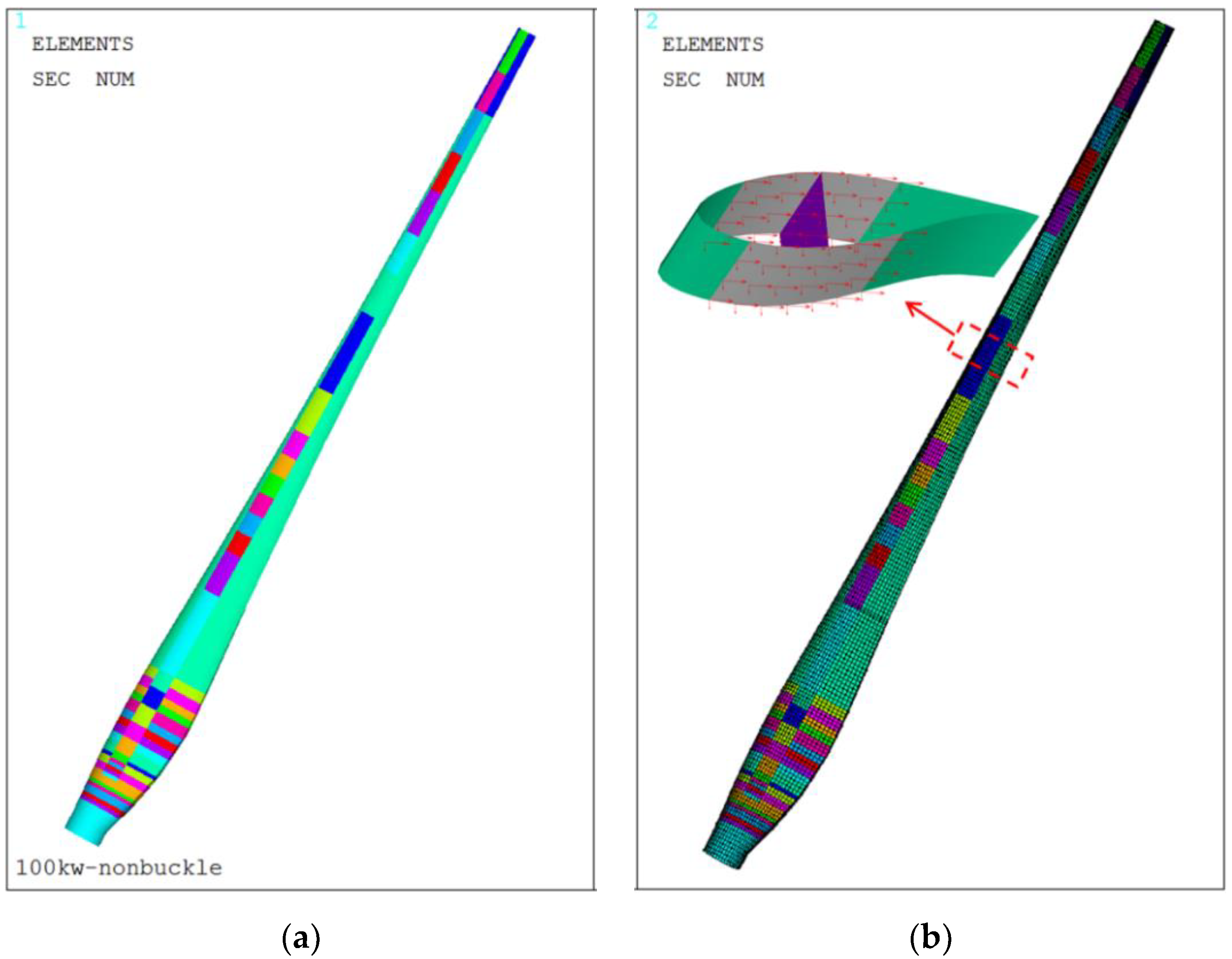
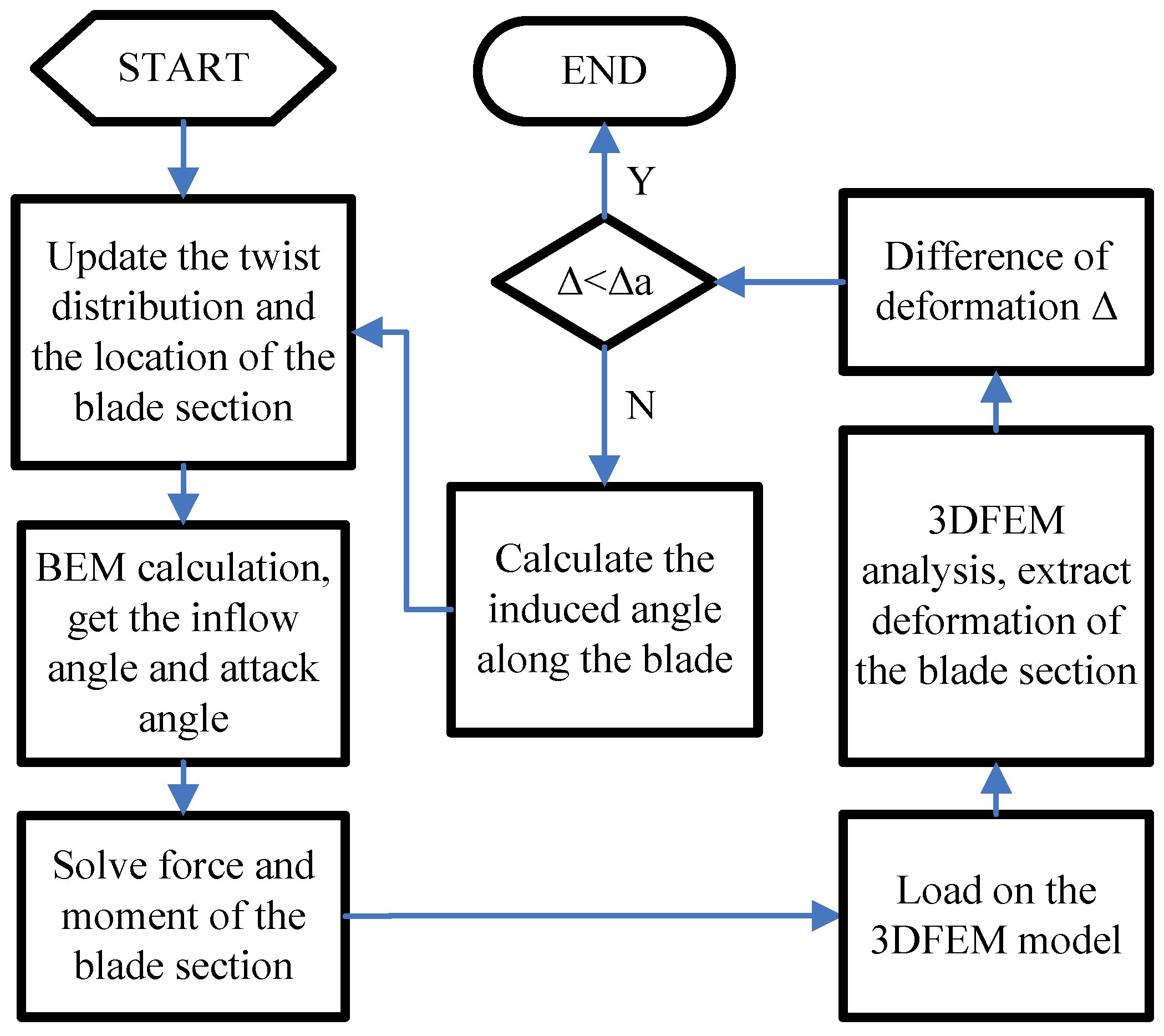
2.3. Building the BEM-3DFEM Model

The aeroelastic process is very complicated. To analyze it, many coupling models have been developed [22,23,24]. The weak coupling method, due to its advantage of keeping the independence of the aerodynamic model and structure model and its expansibility, has been widely used in fluid-structure coupling analysis cases. In this paper, based on the above BEM method and 3DFEM model, an aeroelastic coupling model, named as BEM-3DFEM, was established by using a weak coupling method. The calculation process of the BEM-3DFEM is shown in Figure 3. During the calculating process, the loads were firstly calculated by the BEM method and loaded on the 3DFEM model of the blade to get the deflections of the blade. Then, the induced twist of every section used in BEM were gotten by interpolating the information of the nodes nearby. After that, the induced twist of every section were used in BEM computation to change the loads on the structure model. So, the deformations of the blade also change by the loads. If the difference of the deformation between two adjacent iterations, expressed as Δ , is less than the tolerance Δ a , the analysis process ends. At the same time, the final pretwist angle distribution is obtained. At this point, a steady aeroelastic analysis has been done.

3. An Aeroelastic Coupling Optimization Model

3.1. Objective Function

The power output is one of the most important properties of the wind turbine, so the maximum A E P considering the aeroelastic effect was selected as the objective function. It is shown as follows:
max { A E P } = max { N h v i n v o u t P ( v ) f ( v ) d v }
where v i n and v o u t are cut-in and cut-out wind speed, respectively; N h is the number of hours in a year; P(v) is the power of the wind turbine at the wind speed of v, taking the aeroelastic effect into account; and f(v) is the probability of the wind speed of v in a year.
In this article, the Rayleigh distribution with the average wind speed of 8 m/s in a year was used to calculate the f(v).

3.2. Free Variables

The twist plays an important role in the aerodynamic design of a blade. Its change can reflect the aeroelastic effect. Hence, in this optimization model, pretwist angles at different cross-sections of the blade were selected as free variables, which are named as x i ( i = 1 , 2 , 3 n ) , where x i is the pretwist angle at section i and n is the number of the sections used to compute the power.
After getting the x i , the origin twist at the section i is pretwisted by x i .

3.3. Constraints

In this optimization model, to achieve the excellent aerodynamic performance of the blade, some constraints about the x i are given.
Firstly, on the one hand, x i should not be too big. This is because a big x i makes the attack angle of the section i exceed the stall attack angle. On the other hand, x i should not be too small. This leads to the aerodynamic twist becoming bigger than the allowed value, which is limited by the production and transportation. So, it is expressed as follows:
L b i c x i U b i + c
where L b i is the minimum induced twist from computing the twist change at the different wind speed, considering the aeroelastic effect for the origin blade; U b i is the maximum induced twist from computing the twist change at the different wind speed, considering the aeroelastic effect for the origin blade; and c is a constant value, which is used to expand the searching range of x i . In this article, it was decided by the difference of the U b i to the stall attack angle at section i .
Secondly, to keep the smoothness of the aerodynamic shape of the blade, the twist distribution along the blade after pretwisting should meet a curve of nine times polynomial. It is written as:
x i 0 x i = a 0 + a 1 r i + a 2 r i 2 + a 3 r i 3 + a 4 r i 4 + a 5 r i 5 + a 6 r i 6 + a 7 r i 7 + a 8 r i 8 + a 9 r i 9
where x i 0 is the twist at the section i of the origin blade; r i corresponds to the location of the section i span-wise from root to tip; and a i ( i = 0 , 1 , , 9 ) is the coefficient, which is gotten by fitting the twist at different sections after pretwisting.

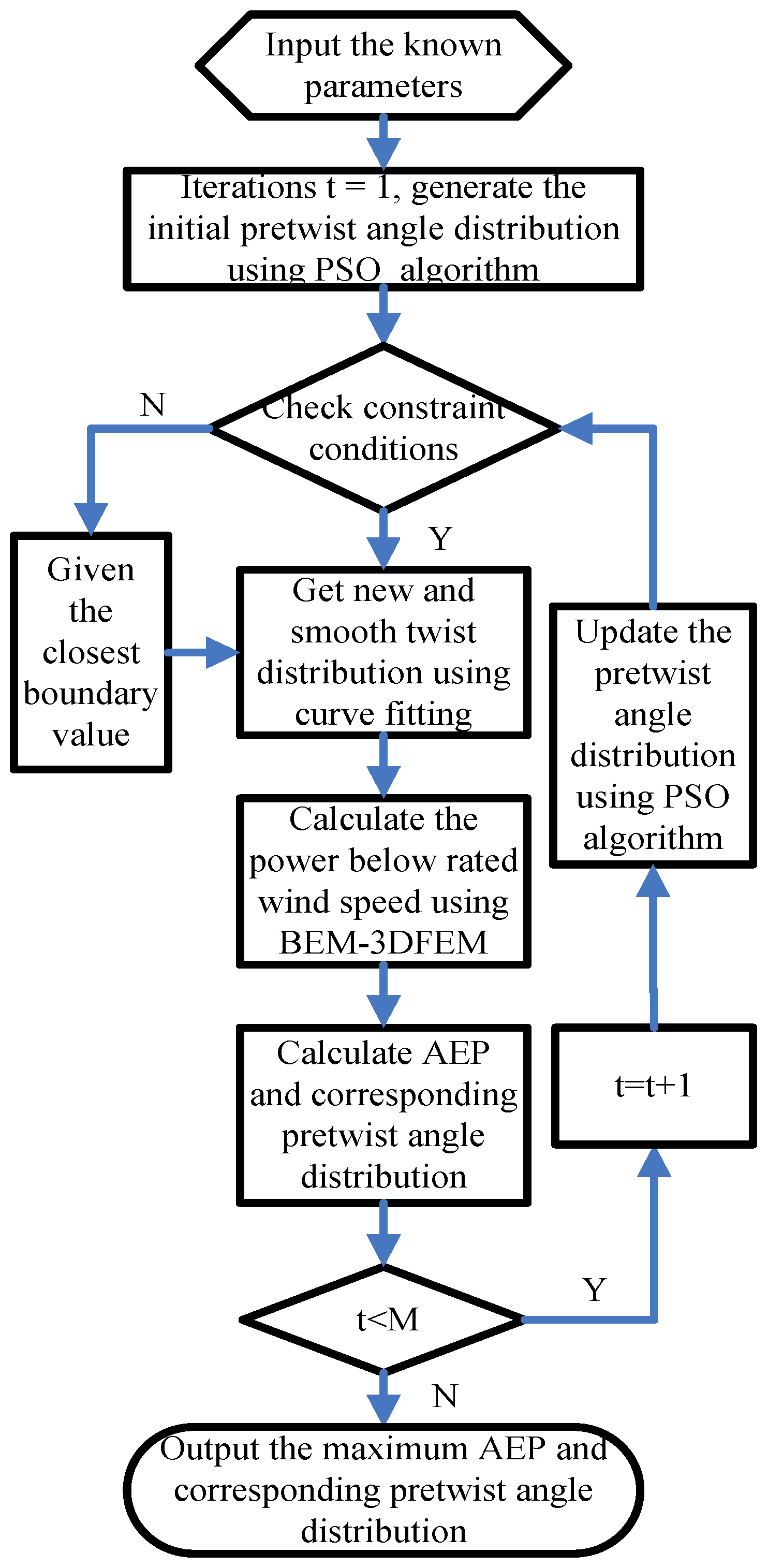
3.4. Optimization Process

The flow chart of the aeroelastic coupling optimization model to get the maximum AEP, as well as the optimal pretwist angle-distribution, is given in Figure 4.
During the optimization, we generated the initial pretwist angle distribution using the PSO algorithm at first. After checking the constraints about the pretwist angle, we obtained a series of smooth twist distributions for different blades. Then, we used the BEM-3DFEM to evaluate the power performance at different wind speeds by considering the aeroelastic effect. The maximum AEP was gotten at the same probability distribution of annual wind speed. With the increase of iteration number, more suitable pretwist angle distributions were generated using the PSO algorithm [25,26,27,28]. Besides, the AEP was calculated again to find better results. While the iteration number was equal to the maximum iteration number M, the optimum AEP, as well as the corresponding pretwist angle distribution, were output.
Therefore, the pretwist angle distribution changed in every iteration by using a linear change inertia weight PSO algorithm. In this way, the attack angle of the section increased in most wind speeds. The power loss due to the aeroelastic influence was made up.

4. Results & Discussion

In this paper, a 100 kW wind turbine blade was analyzed using the above aeroelastic coupling optimization model to compensate the power loss due to the aeroelastic effect. It is a field test wind turbine operated by National Energy Wind Turbine Blade R&D Center and located in Zhangbei County, China. It is also a VSVP (variable speed variable pitch) wind turbine, like the large scale wind turbines. So, the power under the rated wind speed is mainly studied. Besides, the induced twists of the blade are small due to the relatively large stiffness of the blade. A high precision model, especially the structure model, is needed to simulate the deflection of the blade. Fortunately, the BEM-3DFEM model can efficiently reflect the aeroelastic influence of this blade because it simulates the blade layers in detail.

4.1. Pre-Assigned Variables

During the computing process, some of the parameters were fixed. They are as follows:
  • PSO algorithm, such as inertial weight, accelerating factors;
  • Aerodynamic profile, such as chord distribution, twist distribution, relative thickness distribution;
  • Structure layers, such as the number, size, location, materials; and
  • Some other parameters about the wind turbine, such as the hub height, hub radius, cut-in wind speed, cut-out wind speed, rated wind speed.
Some typical parameters among them are given in Table 2. In Table 2, the first six parameters were used in the PSO algorithm. The inertial weights and accelerating factors were selected according to the Ref. [26,27,28]. The maximum number of iterations and number of individuals were relatively small to reduce the calculating time due to the high computing cost of FEM analysis. The 7th to 10th parameters in this table were used to describe the 100 kW wind turbine. So, their values were fixed. The last parameter was used for evaluating the convergence of the steady aeroelastic analysis. Its value was small enough for 100 kW wind turbine to get the correct blade deflection. However, we should be concerned; this value cannot be too small as this would lead to the non-convergence of the FEM-3DFEM analysis. In addition, this value changes for different wind turbines.

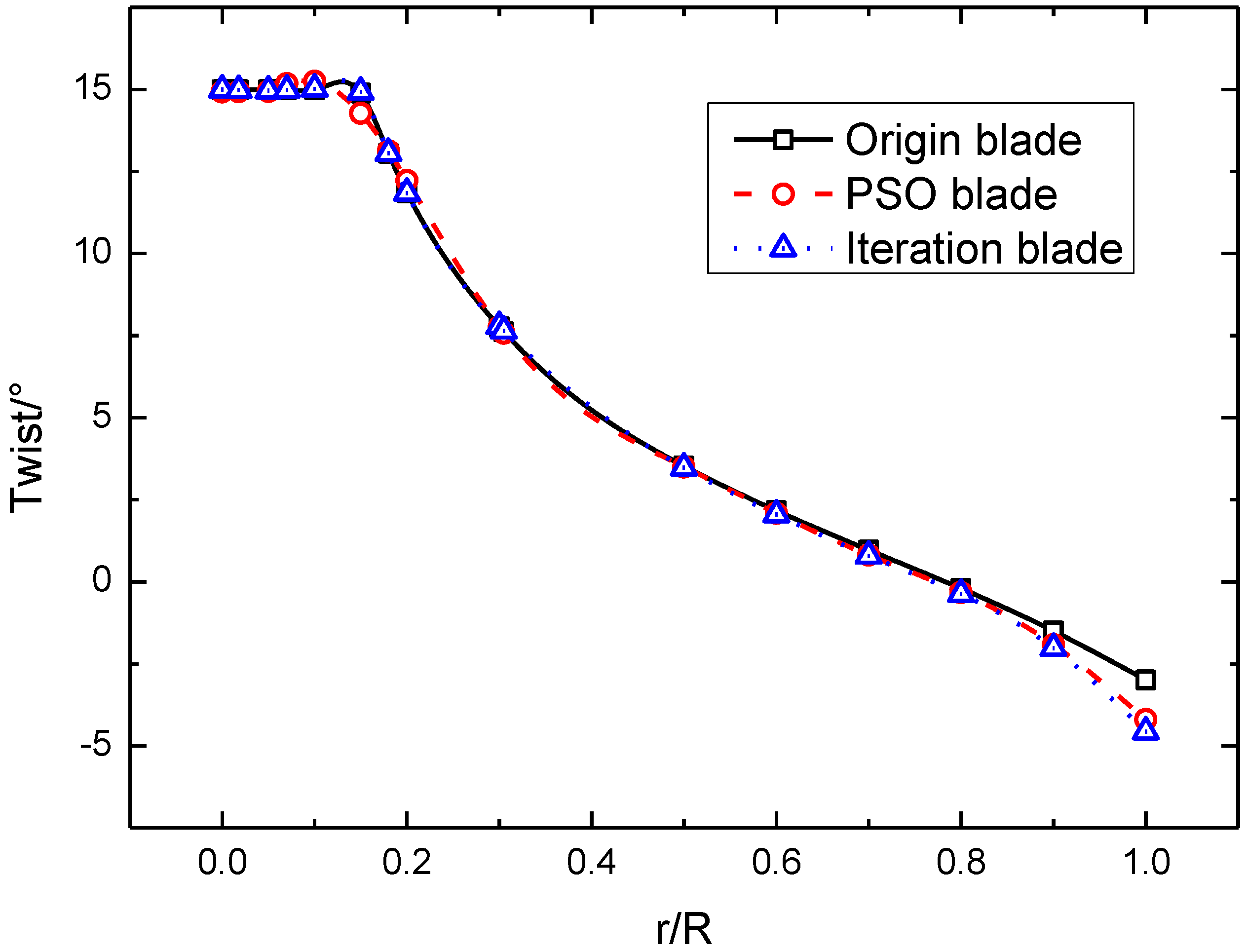
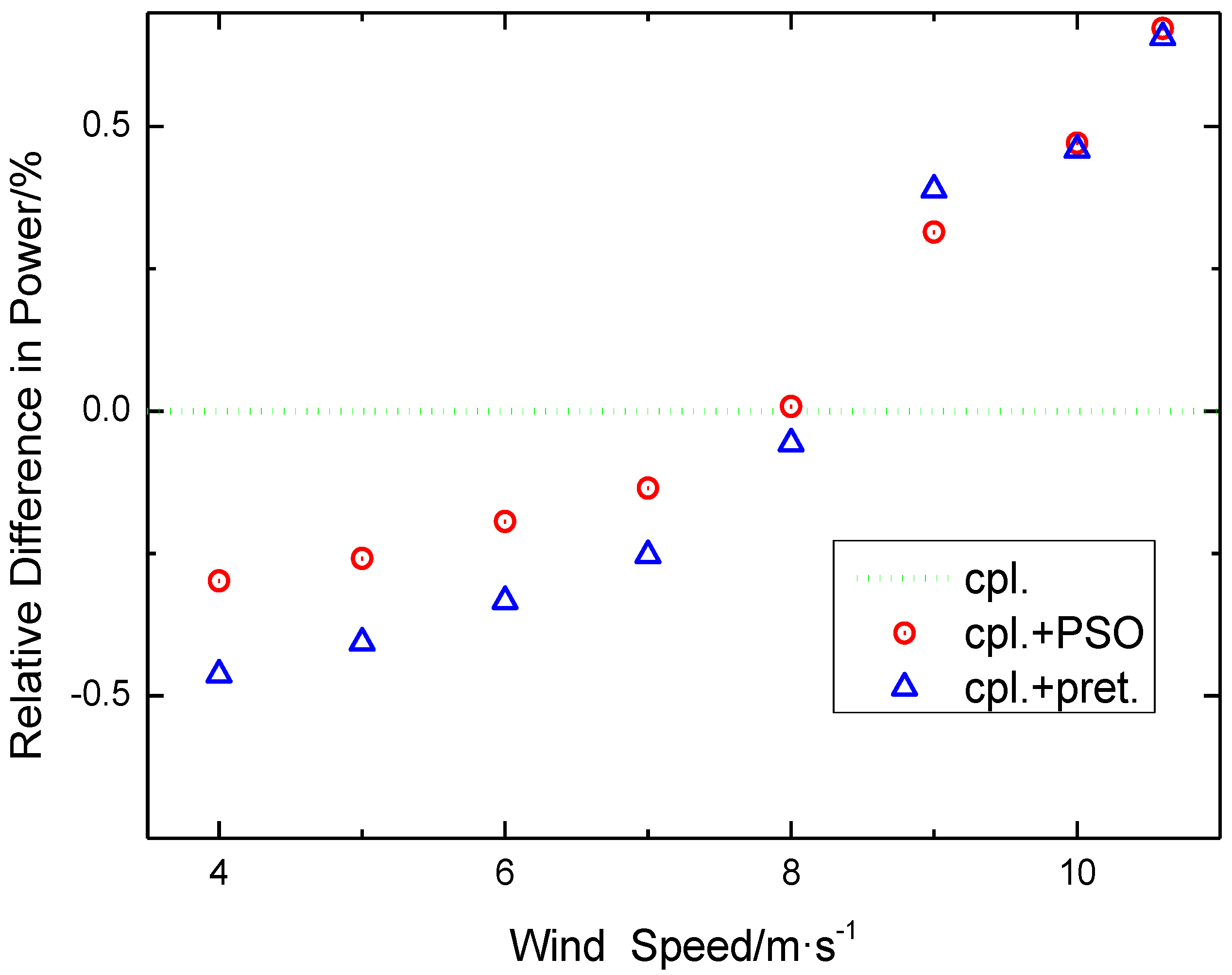
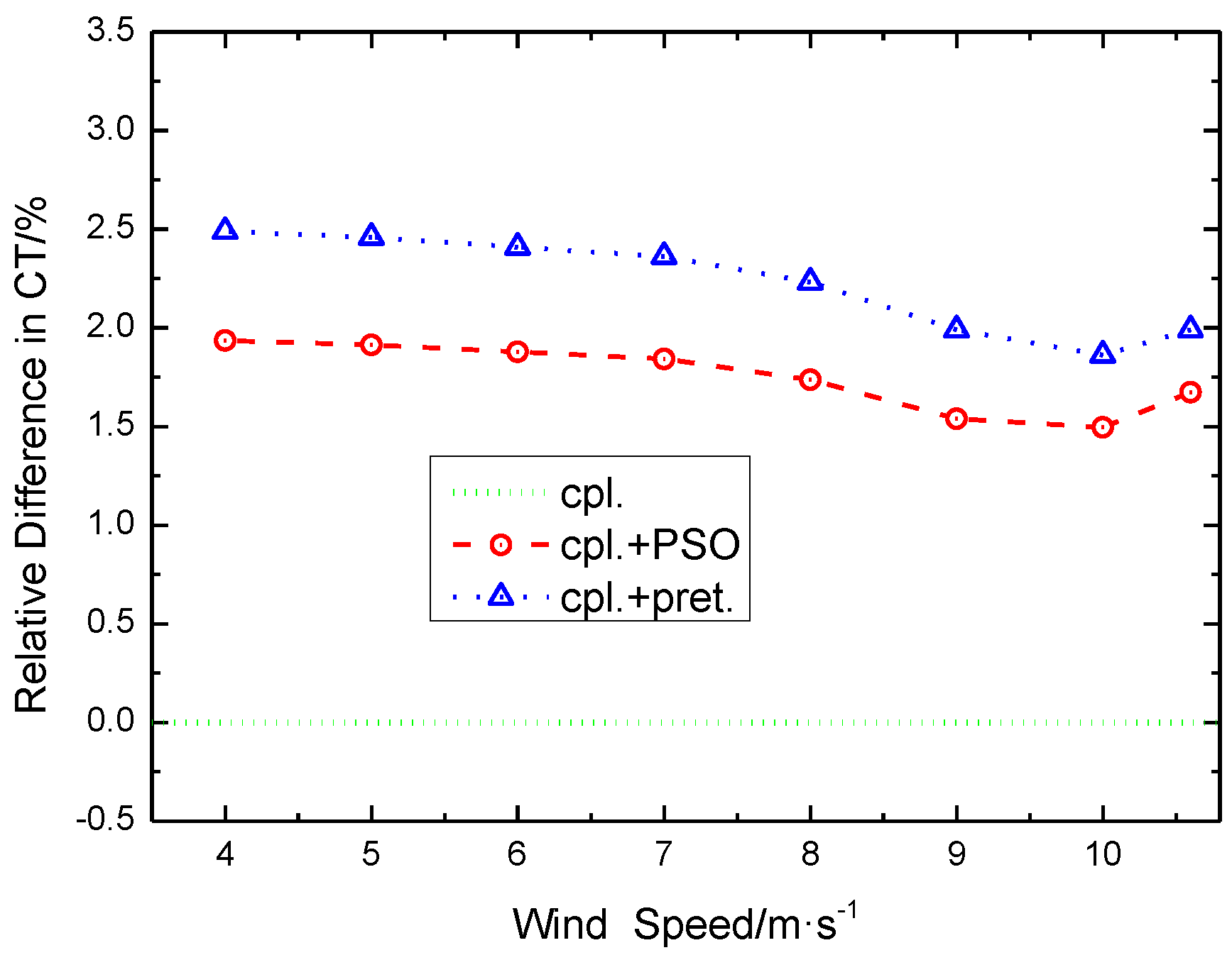
4.2. Results and Analysis

To analyze the benefits of the aeroelastic coupling optimization model, we applied the optimization model and the iteration method in Ref. [8] to the origin blade. Two new blades were gotten, and named as the PSO blade and the iteration blade. The AEP under four different cases was computed. The cases are as follows:
  • The origin blade without considering the aeroelastic coupling effect, which is represented as ucpl.;
  • The origin blade considering the aeroelastic coupling effect, which is represented as cpl.;
  • The PSO blade considering the aeroelastic effect, which is represented as PSO + cpl.; and
  • The iteration blade considering the aeroelastic effect, which is represented as pret. + cpl.
When the AEP was calculated, wind speeds from 4 to 25 m/s with an interval of 1 m/s, as well as the rated wind speed of 10.6 m/s, were used. However, only wind speeds from 4 to 10.6 m/s consider the aeroelastic effect, because the blade was used on a VSVP wind turbine. Besides, for the different reference wind speeds, different pretwisting angle distributions were gotten using the iteration method. This led to different AEP. In this article, lots of AEP using the iteration method were calculated by varying the reference wind speed from 4 to 10.6 m/s. Then, the maximum value of them, with reference wind speed of 10 m/s, was selected as the result of the iteration blade.
The twist distribution along the blade for the origin blade, the PSO blade, and the iteration blade are given in Figure 5. The relative difference in AEP for different cases compared to the ucpl. case is shown in Figure 6. We can see that the AEP of the origin blade decreases due to the aeroelastic effect. This feature is the same as the result of other researches [8,9,10,11]. In addition, the AEP of the PSO blade and the iteration blade are higher than that of the origin blade considering the aeroelastic effect. It indicates that the optimization model and the iteration method can both compensate the power loss and make the AEP close to that of the ucpl. case. Based on the varieties of the twist distribution in Figure 5, we can conclude that reducing the twists of the blade, especially that of the outboard part of the blade, leads to the increase of AEP to some extent. By comparing the twist distribution of the PSO blade with that of the iteration blade, it indicates that the AEP does not continuously rise while the twist keeps going down. This is because the ratio of the lift to drag, as well as the lift coefficient, cannot continue to increase while the attack angle gets bigger. So, there exists an optimal twist distribution to get the maximum AEP under the consideration of the aeroelastic influence.
From Figure 5 and Figure 6, we can see that by using the optimization model, the PSO blade gets the maximum AEP and its twist distribution is very smooth. It shows that the optimization model is more efficient to compensate for power loss than the iteration method. Therefore, it gives us a good choice to improve the power output of the blade, while the aeroelastic effect cannot be negligible.
Figure 7 and Figure 8 illustrate the relative difference in power and thrust coefficient compared to the cpl. Case, respectively. From Figure 7, we can see, in the case of considering the aeroelastic effect, the powers of the PSO blade and the iteration blade are higher than that of the origin blade at high wind speed. However, the comparison results about the power are converse at low wind speed. It can be concluded that the enhancements of the powers at high wind speed play the leading role in raising the AEP of the PSO blade and the iteration blade. This may be caused by the stronger aeroelastic coupling at high wind speed.
Figure 8 shows the increase of the thrust coefficients of the PSO blade and the iteration blade at every wind speed. This is mainly due to the increase of the attack angle by pretwisting the origin blade. In the future design, this should be a constraint condition for getting the maximum AEP. By comparing the PSO blade with the iteration blade, we can find that the thrust coefficients of the PSO blade are less than that of the iteration blade, while the powers of the PSO blade are larger than that of the iteration blade, at most of the wind speeds. This is mainly because the attack angles and the inflow angles of different sections change at the same time after pretwisting. However, the optimization model can help us to find out the more suitable values for them. This is a good advantage of the optimization model.
Certainly, the above result are based on the steady aeroelastic analysis. This is because we just applied the steady BEM model in the BEM-3DFEM. For the evaluation of AEP, this steady model is suitable. However, the wind turbine always operates in unsteady wind conditions. This needs an unsteady aerodynamic model to simulate the aerodynamic force. Hence, to calculate the aeroelastic loads in unsteady conditions, the steady BEM model needs to be corrected by using the dynamic stall model, or even replaced by the vortex method or unsteady CFD model. The BEM-3DFEM model will be improved in the future to compute the effect of the PSO blade under turbulence wind.

5. Conclusions

In this article, to get the maximum AEP and the optimal pretwist angle distribution, an aeroelastic coupling optimization model, combining the PSO algorithm with the BEM-3DFEM model, was built to compensate power loss due to the aeroelastic effect.
Then, this aeroelastic coupling optimization model was applied to a 100 kW wind turbine blade to reduce the power loss. The iteration method developed to solve this problem from Ref. [8] was also used for the same blade. Two new blades with different aerodynamic profiles were gotten, respectively. After that, different aerodynamic properties for these two new blades, as well as the origin blade, were calculated and compared.
It is shown that the AEP of the origin blade reduces due to the aeroelastic effect. This feature is the same as the result of other researches [8,9,10,11]. In addition, the AEP of the origin blade with the aeroelastic effect can be improved by pretwisting the origin blade, whether using the aeroelastic coupling optimization model or the iteration method. Compared with the iteration method, the optimization model is more efficient to compensate for the power loss, with a lower thrust coefficient while keeping the twist distribution smooth. Therefore, it gives us a good choice to improve the power output of the origin blade, while the aeroelastic effect cannot be negligible.
According to the results, the enhancements of the powers at high wind speed play the leading role in raising the AEP for both the PSO blade and the iteration blade. This may be caused by the stronger aeroelastic process at high wind speed. So, we can conclude that the improvement of the AEP is more obvious when the wind turbine is used in a better wind resource area. However, the thrust coefficients increase after pretwisting the origin blade, since the attack angles enlarge. Hence, to avoid the thrust of the blade exceeding the allowable value, the thrust coefficient should be taken as a constraint condition while getting the maximum AEP in the future.
Besides, the results of compensating for the power loss on the 100 kW wind turbine blade are relatively small. This may be because the aeroelastic effect of the 100 kW wind turbine blade is weak. To further certify this optimization model, it will be used on some large-scale wind turbines such as the NREL 5MW reference wind turbine and the DTU (Danmarks Tekniske Universitet) 10MW reference wind turbine. Certainly, this article focuses on steady aeroelastic analysis. This is because we just applied the steady BEM model in the BEM-3DFEM. To simulate aeroelastic loads in unsteady conditions, the steady BEM model needs to be corrected by using the dynamic stall model, or replaced by the vortex method or even the unsteady CFD model. This BEM-3DFEM model will be improved in the future to compute the effect of the PSO blade under turbulence wind.

Author Contributions

Y.Z. developed most of the procedure, did the numerical computation, and wrote the article; C.L. developed the new idea, did the analysis of the results, and reviewed the article; Z.Q. developed the APDL procedure for FEM analysis and modified the article; K.Y. supervised the work and gave some useful comments for writing.

Funding

This research was funded by the National Natural Science Foundation of China (No. 51606196).

Acknowledgments

The authors would like to thank the China Scholarship Council (CSC) and the International Clean Energy Talent (iCET) Program. This work was also supported by the Strategic Priority Research Program of the Chinese Academy of Science, Grant No. XDA21050303.

Conflicts of Interest

The authors declare no conflict of interest.

References

  1. Bavanish, B.; Thyagarajan, K. Optimization of power coefficient on a horizontal axis wind turbine using bem theory. Renew. Sustain. Energy Rev. 2013, 26, 169–182. [Google Scholar] [CrossRef]
  2. Liu, X.W.; Wang, L.; Tang, X.Z. Optimized linearization of chord and twist angle profiles for fixed-pitch fixed-speed wind turbine blades. Renew. Energy 2013, 57, 111–119. [Google Scholar] [CrossRef]
  3. Saenz-Aguirre, A.; Fernandez-Gamiz, U.; Zulueta, E.; Ulazia, A.; Martinez-Rico, J. Optimal Wind Turbine Operation By Artificial Neural Network-based Active Gurney Flap Flow Control. Sustainability 2019, 11, 2809. [Google Scholar] [CrossRef]
  4. Fernandez-Gamiz, U.; Zulueta, E.; Boyano, A.; Ansoategui, I.; Uriarte, I. Five Megawatt Wind Turbine Power Output Improvements By Passive Flow Control Devices. Energies 2017, 10, 742. [Google Scholar] [CrossRef]
  5. Fernandez-Gamiz, U.; Zulueta, E.; Boyano, A.; Ramos-Hernanz, J.A.; Lopez-Guede, J.M. Microtab Design And Implementation On A 5 Mw Wind Turbine. Appl. Sci. 2017, 7, 536. [Google Scholar] [CrossRef]
  6. González-González, A.; Etxeberria-Agiriano, I.; Zuluet, E.; Oterino-Echavarri, F.; Lopez-Guede, J.M. Pitch Based Wind Turbine Intelligent Speed Setpoint Adjustment Algorithms. Energies 2014, 7, 3793–3809. [Google Scholar] [CrossRef]
  7. Kusiak, A.; Zheng, H.Y.; Song, Z. Power optimization of wind turbines with data mining and evolutionary computation. Renew. Energy 2010, 35, 695–702. [Google Scholar] [CrossRef]
  8. Stäblein, A.R.; Tibaldi, C.; Hansen, M.H. Using Pretwist to Reduce Power Loss of Bend-Twist Coupled Blades. In Proceedings of the 34th Wind Energy Symposium, San Diego, CA, USA, 4–8 January 2016; American Institute of Aeronautics & Astronautics: San Diego, CA, USA, 2016. AIAA 2016-1010. [Google Scholar] [Green Version]
  9. Lobitz, D.W.; Veers, P.S. Load Mitigation with Bending/Twist-coupled Blades on Rotors using Modern Control Strategies. Wind Energy 2003, 6, 105–117. [Google Scholar] [CrossRef]
  10. Verelst, D.R.; Larsen, T.J. Load Consequences When Sweeping Blades—A Case Study of a 5 MW Pitch Controlled Wind Turbine; Risø-R-Report; Risø National Laboratory for Sustainable Energy: Roskilde, Denmark, 2010; Risø-R-1724(EN). [Google Scholar]
  11. Lee, Y.J.; Jhan, Y.T.; Chung, C.H. Fluid–structure interaction of FRP wind turbine blades under aerodynamic effect. Compos. Part B Eng. 2012, 43, 2180–2191. [Google Scholar] [CrossRef]
  12. Bottasso, C.L.; Campagnolo, F.; Croce, A.; Tibaldi, C. Optimization-Based Study of Bend-Twist Coupled Rotor Blades for Passive and Integrated Passive/Active Load Alleviation. Wind Energy 2013, 16, 1149–1166. [Google Scholar] [CrossRef]
  13. Hansen, M.O.L. Aerodynamics of Wind Turbines; Earthscan Publications Ltd.: London, UK, 2008. [Google Scholar]
  14. Hansen, M.O.L.; Sørensen, J.N.; Voutsinas, S.; Sørensen, N.; Madsen, H.A. State of the art in wind turbine aerodynamics and aeroelasticity. Prog. Aerosp. Sci. 2006, 42, 285–330. [Google Scholar] [CrossRef]
  15. Wang, L.; Liu, X.W.; Kolios, A. State of the art in the aeroelasticity of wind turbine blades: Aeroelastic modelling. Renew. Sustain. Energy Rev. 2016, 64, 195–210. [Google Scholar] [CrossRef] [Green Version]
  16. Bai, C.J.; Wang, W.C. Review of computational and experimental approaches to analysis of aerodynamic performance in horizontal-axis wind turbines (HAWTs). Renew. Sustain. Energy Rev. 2016, 63, 506–519. [Google Scholar] [CrossRef]
  17. Hand, M.M.; Simms, D.A.; Fingersh, L.J.; Jager, D.W.; Cotrell, J.R.; Schreck, S.; Larwood, S.M. Unsteady Aerodynamics Experiment Phase VI: Wind Tunnel Test Configurations and Available Data Campaigns; Techinical Report; National Renewable Energy Laboratory: Golden, CO, USA, 2001; NREL/TP-500-29955.
  18. Simms, D.; Schreck, S.; Hand, M.; Fingersh, L.J. NREL Unsteady Aerodynamics Experiment in the NASA-Ames Wind Tunnel: A Comparison of Predictions to Measurements; Techinical Report; National Renewable Energy Laboratory: Golden, Colorado, USA, 2001; NREL/TP-500-29494.
  19. Bossanyi, E.A. GH Bladed Theory Manual; Garrad Hassan and Partners Limited: Bristol, UK, 2008. [Google Scholar]
  20. Hayat, K.; Ha, S.K. Load mitigation of wind turbine blade by aeroelastic tailoring via unbalanced laminates composites. Compos. Struct. 2015, 128, 122–133. [Google Scholar] [CrossRef]
  21. Chen, X.; Qin, Z.W.; Yang, K.; Zhao, X.L.; Xu, J.Z. Numerical Analysis and Experimental Investigation of Wind Turbine Blades with Innovative Features: Structural Response and Characteristics. Sci. China Tech. Sci. 2014, 58, 1–8. [Google Scholar] [CrossRef]
  22. Li, Y.; Castro, A.M.; Sinokrot, T.; Prescott, W.; Carrica, P.M. Coupled multi-body dynamics and CFD for wind turbine simulation including explicit wind turbulence. Renew. Energy 2015, 76, 338–361. [Google Scholar] [CrossRef]
  23. Mo, W.W.; Li, D.Y.; Wang, X.N.; Zhong, C.T. Aeroelastic Coupling Analysis of the Flexible Blade of a Wind Turbine. Energy 2015, 89, 1001–1009. [Google Scholar] [CrossRef]
  24. Lee, J.W.; Lee, J.S.; Han, J.H.; Shin, H.K. Aeroelastic analysis of wind turbine blades based on modified strip theory. J. Wind Eng. Ind. Aerodyn. 2012, 110, 62–69. [Google Scholar] [CrossRef]
  25. Liao, C.C.; Zhao, X.L.; Xu, J.Z. Blade layers optimization of wind turbines using FAST and improved PSO algorithm. Renew. Energy 2012, 42, 227–233. [Google Scholar]
  26. Shi, Y.; Eberhart, R.C. Empirical study of particle swarm optimization. Evolutionary Computation. In Proceedings of the 1999 Congress on Evolutionary Computation-CEC99, Washington, DC, USA, 6–9 July 1999; pp. 1945–1950. [Google Scholar]
  27. Shi, Y.; Eberhart, R.C. A modified particle swarm optimizer. Evolutionary Computation. In Proceedings of the IEEE World Congress on Computational Intelligence, Anchorage, AK, USA, 4–9 May 1998; pp. 69–73. [Google Scholar]
  28. Eberhart, R.; Kennedy, J. A New Optimizer Using Particle Swarm Theory. In Proceedings of the Sixth International Symposium on Micro Machine and Human Science, Nagoya, Japan, 4–6 October 1995; pp. 39–43. [Google Scholar]
Figure 1. Aerodynamic performance of the NREL phase VI wind turbine from different methods: (a) Power coefficient changing with tip speed ratio; (b) power changing with wind speed. Note: “BEM” stands for the results obtained from the BEM procedure; “experiment” stands for the measurement results in ref [8]; “bladed” stands for the results by the use of GH Bladed software.
Processes 07 00633 g001
Figure 2. The 3DFEM model of a 100 kW blade: (a) Blade laminates in different colors; (b) meshes and loading of the blade model.
Processes 07 00633 g002
Figure 3. Flow chart of the BEM-3DFEM model.
Processes 07 00633 g003
Figure 4. The flow chart of the aeroelastic coupling optimization model.
Processes 07 00633 g004
Figure 5. Twist distribution along the blade.
Processes 07 00633 g005
Figure 6. The relative difference in annual energy production (AEP) compared to the ucpl. Case.
Processes 07 00633 g006
Figure 7. The relative difference in power compared to the cpl. Case.
Processes 07 00633 g007
Figure 8. Relative difference in thrust coefficient compared to the cpl. Case.
Processes 07 00633 g008
Table 1. Tip deflections of a 100 kW blade.
Experiment (m)FEM (m)Relative Error (%)
1.3691.3302.8
Table 2. Some typical parameters used in this optimization model.
Parameter NamesValues
Maximum inertial weight1
Minimum inertial weight0
accelerating factors c 1 1
accelerating factors c 2 1
Maximum number of iterations M 25
Number of individuals22
Number of the blade sections16
Radius of the rotor (m)10.292
Hub height (m)26.2
Number of blades3
Δ a 1.00 × 10⁻⁶

