Article

Exergy Analysis and Evaluation of the Different Flowsheeting Configurations for CO2 Capture Plant Using 2-Amino-2-Methyl-1-Propanol (AMP)

1
School of Water, Energy and Environment, Cranfield University, College Road, Bedford, Bedfordshire MK43 0AL, UK
2
Gas Turbine and Transmissions Research Center, Faculty of Engineering, University of Nottingham, Nottingham NG7 2RD, UK
3
Department of Chemical Engineering, University of Birmingham, Edgbaston B15 2TT, UK
*
Author to whom correspondence should be addressed.
Processes 2019, 7(6), 391; https://doi.org/10.3390/pr7060391
Submission received: 27 May 2019 / Revised: 18 June 2019 / Accepted: 19 June 2019 / Published: 24 June 2019
(This article belongs to the Special Issue Gas Capture Processes)

Abstract

:
This paper presents steady-state simulation and exergy analysis of the 2-amino-2-methyl-1-propanol (AMP)-based post-combustion capture (PCC) plant. Exergy analysis provides the identification of the location, sources of thermodynamic inefficiencies, and magnitude in a thermal system. Furthermore, thermodynamic analysis of different configurations of the process helps to identify opportunities for reducing the steam requirements for each of the configurations. Exergy analysis performed for the AMP-based plant and the different configurations revealed that the rich split with intercooling configuration gave the highest exergy efficiency of 73.6%, while that of the intercooling and the reference AMP-based plant were 57.3% and 55.8% respectively. Thus, exergy analysis of flowsheeting configurations can lead to significant improvements in plant performance and lead to cost reduction for amine-based CO2 capture technologies.

1. Introduction

Natural gas power plants play a vital role in meeting energy demands. Power generation from gas-fired power plants produces lots of emissions, which increases the concentration of greenhouse gases in the atmosphere. Thus, CO2 emissions reduction is a high priority demand, and one of the solutions to this problem is carbon capture and storage (CCS). The main restriction for deploying large-scale CO2 capture systems is that these processes reduce the plant net power output for fixed energy due to the addition of carbon capture plant, thereby increasing the net cost of capture [1]. However, the cost associated with commercial capture plants is about 80% of CCS cost [2], which poses a major setback. The reduction in the power output is as a result of the parasitic load of the capture plant, the load demand comes from the reboiler steam requirements drivers such as pumps, compressors, cooling duty needed for the amine process, etc. leading to an energy penalty. This energy penalty can be reduced in a number of ways, many of which are specific to the capture technology employed. For absorption processes, the total reboiler energy can be lowered by an improved process design of the solvent plant [3,4]. Examples of these improved process design include absorber intercooling, rich split, lean amine flash, vapor recompression, configurations and stripping with flash steam, etc. The total energy consumption can be reduced up to 20% in pilot-scale plant studies for the different configurations compared to the conventional amine plants [5].
Several configurations for minimizing energy consumption have been suggested and studied. Leites et al. [6] modelled the intercooler and varied temperatures between 40–80 °C, the whole liquid was removed from the column at each cooling stage and pumped to 1.1 bar to overcome pressure drop. It was concluded that cooling to 40 °C was found to have the maximum effect on reboiler duty and also minimization of additional equipment. Karimi et al. [7] investigated the intercooling effect in CO2 capture energy consumption, the optimal location for intercooling was about 1/4th to 1/5th of the height of the column from the bottom which brought about 2.84% savings in reboiler energy and it was concluded that intercooling is an option for reducing energy consumption. Aroonwilas and Veawab [8] modelled an intercooler configuration which has been integrated with an amine process to evaluate the energy savings effect as a result of enhanced working capacity. The methodology involved the withdrawal of all the liquid at 1/5th of the column height from the bottom and cooled at 45 °C by varying the lean loading between 0.12–0.25 mol CO2/mol monoethanolamine (MEA). With the intercooling, a reduction of 10% in the solvent required led to energy savings in the stripper reboiler and also, it was concluded that lean loading above 0.18 mol CO2/mol MEA had a minimal effect on reboiler duty. Reddy et al. [9] modelled lean amine flash configuration which generates additional steam by flashing hot lean amine leaving the stripper. Results showed 11% reduction in reboiler steam, 16% reduction in cooling water and 6% in stripper diameter. It was observed that hot lean amine temperature was lowered from 120 °C to 103 °C by the flash; this low temperature increases the energy consumption in the stripper bringing about the additional steam generation and improved working capacity. Eisenberg and Johnson [10] modelled a rich split configuration and this resulted in 7.1% savings in reboiler duty over the reference case. It was concluded that for loadings greater than 0.15 mol CO2/mol MEA, a clear benefit was obtained. But it was later observed that increasing the packing height for a lean loading of 0.2 mol CO2/mol MEA, for 30% of the cold solvent split, a reboiler duty of 97.8 kW was required, which is about 10.3% higher than the reference case.
Cousins et al. [11] reviewed fifteen amine process configurations (multi-component columns, inter-stage temperature control, heat-integrated stripping column, split flow process, vapor recompression, matrix stripping, heat integration, etc.). The configurations which involved both experimental and simulation-based methods were evaluated with different solvents, and different operating conditions (temperature, pressure and feed composition). It was, therefore, difficult to compare the energy savings on a fair basis. Thus, it was concluded that the configurations considered reduced the energy consumption, but increased the plant complexity. Also, configurations with less additional equipment (e.g., vapor recompression, etc.) gave higher efficiencies than those with more equipment. Ahn et al. [12] evaluated ten different configurations capture plants, this included the multiple alterations (absorber intercooling combined with condensate evaporation and lean amine flash) which were novel in the study using 30 wt% MEA to capture 90% CO2, reboiler duty savings was maximized by simultaneous application of previous strategies. The comparison was based on total energy consumption (thermal and electrical energy used), the multiple strategies achieved a greater reduction in the energy requirement reducing steam consumption by up to 37% when compared to the simple absorber/stripper configurations. Sharma et al. [13] reviewed and assessed the advantages of fourteen different flow sheeting configurations. The comparison was based on cooling duty and equivalent work. Results showed pump-around was more beneficial than intercooling, while intercooling with rich split was found to be the most beneficial based on additional equipment, and the equivalent energy consumption was 12.9% reduction over the base case. Lars et al. [14] compared different configurations; vapor recompression with split stream gave the best reduction of 11% compared to the conventional. Liang et al. [15] studied five different flow sheeting configurations, the new innovation was the combination of split flow with overhead exchanger and improved split flow with vapor recompression. These innovations decreased equivalent work by 17.21% and 17.52% respectively. Jung et al. [16] suggested a new combination; rich vapor recompression and cold solvent split. Results showed that reboiler heat was reduced from 3.44 MJ/kg CO2 to 2.75 MJ/kg CO2. All of these configurations presented above (summarised in Table 1) have achieved the aim of reducing the energy consumption for the MEA capture plant compared to the conventional flowsheet.
Also, rate-based modelling of CO2 absorption in a packed column using AMP solutions for the capture plant has been carried out in the literature. Alatiqi et al. [21] used a rate-based model in simulating CO2 absorption in AMP, MEA, and diethanolamine (DEA) solution. AMP was used to compare the absorption of CO2 in MEA and DEA solutions. Aboudheir et al. [22] used a rate-based model in simulating the absorption of CO2 using AMP solutions. Results were validated with experimental plant data. Gabrielsen et al. [23,24] carried out an experimental study using AMP solution and this was used as validation for the simulation of a rate-based model for CO2 capture in a structured packed column. Afkhamipour and Mofarahi [25] compared rate-based and equilibrium-based models simulation results of a packed column using AMP solution. The rate-based models gave a better prediction of the concentration and temperature profiles than the equilibrium based. Dash et al. [26] explored the benefits of using blended solvents AMP with Piperazine (PZ). These studies presented above have all worked on models for the AMP capture process. There are limited studies on the different configurations using the AMP solvent. Kvamsdal et al. [27] presented a simulated model for the Cesar 1 (AMP + PZ) involving modifications such as intercooling and vapor recompression. The comparison was made with the MEA process using the same modifications. Results showed that the MEA process had lower energy requirements as compared to Cesar 1. Energy consumption accounts for about 25% of total cost thus, the AMP solvent, which has more favourable operating parameters as compared to the MEA solvent as shown in studies [23,28,29] will further minimize energy requirements which will reduce cost. It is therefore important to develop these configurations and utilize the energy savings provided.
Furthermore, exergy analysis which identifies where exergy is destroyed is carried out. The destruction of exergy in a process is proportional to the entropy generation in it; which accounts for the inefficiencies due to irreversibility [30]. Exergy analysis of capture plants using MEA and ammonia solvents have been carried out by few authors [17,18,19,20] as shown above in Table 1, to investigate the effects of the associated losses. However, studies to analyse where the losses occur in the AMP-based CO2 capture plant is lacking. This study includes (i) steady-state rate-based simulation and conventional exergy analysis of the AMP-based PCC process (ii) evaluation of exergy destruction and efficiency in the AMP capture system, (iii) exergy analysis of the different flowsheeting configurations with AMP solvent.

2. Modelling Framework

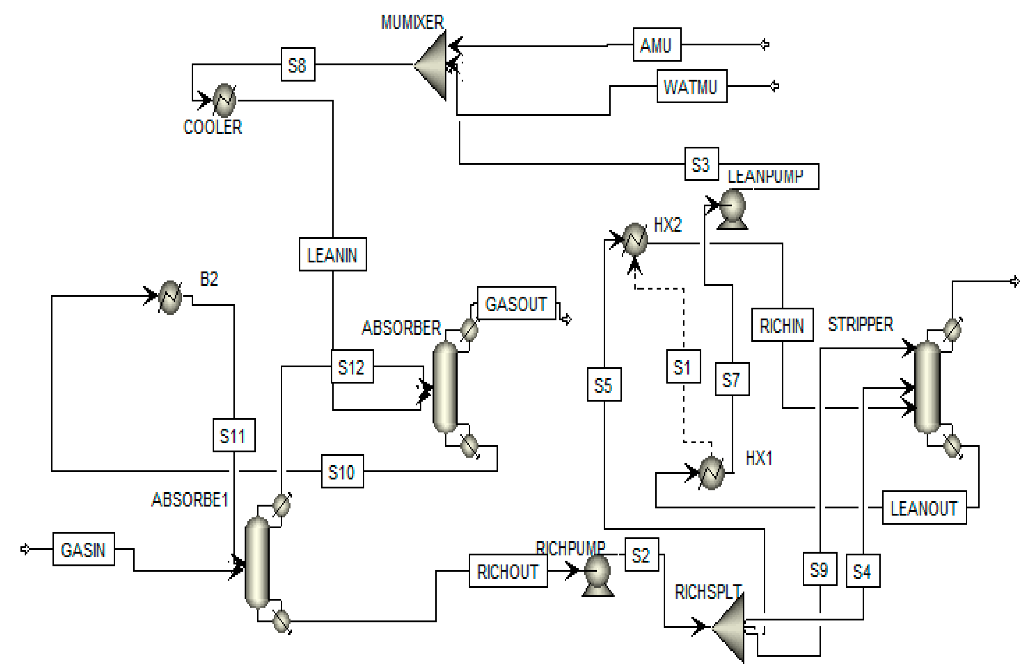
2.1. Model Description of the Capture Plant

The AMP-based process model was developed using the operating parameters in Aspen Plus® software Version (V) 8.4 (Aspen Technology, Inc., Bedford, MA, USA, released in 2013), and consists of an absorber and a stripper column, with a cross heat exchanger and a pump, all connected in a closed loop cycle as described in studies [26,31]. The validation of the capture plant model with experimental data is presented in the literature [26,28].

2.2. Exergy Analysis

Exergy is defined as the maximum theoretical work that is obtained from a system when its state is brought to the reference state [30]. Exergy analysis is a method employed in the evaluation of the use of energy [32]. Exergy gives the identification of the location, the magnitude and the causes of thermodynamic inefficiencies in a thermal system. In this section, the conventional exergy approach is used to evaluate the exergy destruction and potential for improvement of the CO2 capture plant. The values of the exergy reference temperature and pressure, which are default parameters in Aspen Plus® V8.4 simulation tool are 298.15 K and 1.013 bar respectively, and these are used in the simulations. A theoretical process in which the thermodynamic reversibility requires that all the process driving forces such as pressure, temperature and chemical potential differences be zero at all points and times [6] leads to producing a maximum amount of high energy consumption [19]. These losses can be reduced by several methods that are based on the second law of thermodynamics such as the counteraction, quasi-static method and the driving force method [6]. In this study, the driving force method is used to reduce the exergy destruction, leading to a reduction in energy consumption in the AMP-based PCC process and using the same absorbent throughout.
The Aspen Plus® V8.4 exergy estimation property set (EXERGYMS) is used in calculating the methods for physical and chemical exergies of the material and heat flows for each component, using the individual streamflow in the AMP-based capture plant. Furthermore, in other to determine the exergy of the reactions containing electrolytes, the thermodynamic properties of the ionic species of AMP were retrieved from the Aspen Plus® databank, V8.4 (Aspen Technology, Inc., Bedford, MA, USA, released in 2013). The standard Gibbs free energy of formation of AMP in the water at infinite dilution (DGAQFM) values used in this study are based on an estimate given in studies [33,34]. Gibbs free energy data which is called from Aspen database is used in the estimation of Gibbs free energy using the empirical relation in Aspen Plus® V8.4 software. The DGAQFM values of −1.628054 × 10⁸ J/kmol and 4.574 × 10⁸ J/kmol were obtained for AMPH+ (AMP protonation) and AMPCOO- (AMP carbamate formation) respectively. Table 2 below shows the exergy destruction and efficiencies for the equipment in the AMP-based PCC process.
The equations below are used in evaluating the individual component and the total exergy destruction rate within a component. Thus, the exergy balance [35] for the whole system are given in Equations (1)–(3), while the exergetic performance of the AMP-based capture plant is given in Table 2. Equation 1 which is the fuel exergy of each component is as follows:
E f u e l ( t o t a l ) =   E p r o d u c t ( t o t a l )   + E D e s t r u c t i o n ( t o t a l )   + E L o s s e s ( t o t a l )
While for the exergy efficiency of each component (n) which accounts for the thermodynamic losses is given as shown in Equation (2):
E ( n ) =   E p r o d u c t ( n ) / E f u e l ( n )
And the exergy destruction ratio of the nth component is presented in Equation (3):
X d ( n ) =   E D e s t r u c t i o n ( n )   /   E f u e l ( t o t a l )
Table 2, shows the exergy destruction and efficiency for the sub components in the AMP-based capture plant. As observed, the absorber and stripper components had exergy efficiency of 59.8 and 88.5%, respectively, while the heat exchanger gave the lowest exergy efficiency of 25%, these values are close in range with the literature [19].

3. Flowsheeting Configurations

The amine flow sheeting configurations are set up for the capture plant. The reference plant is the standard AMP-based capture plant configuration, as described in Section 2.

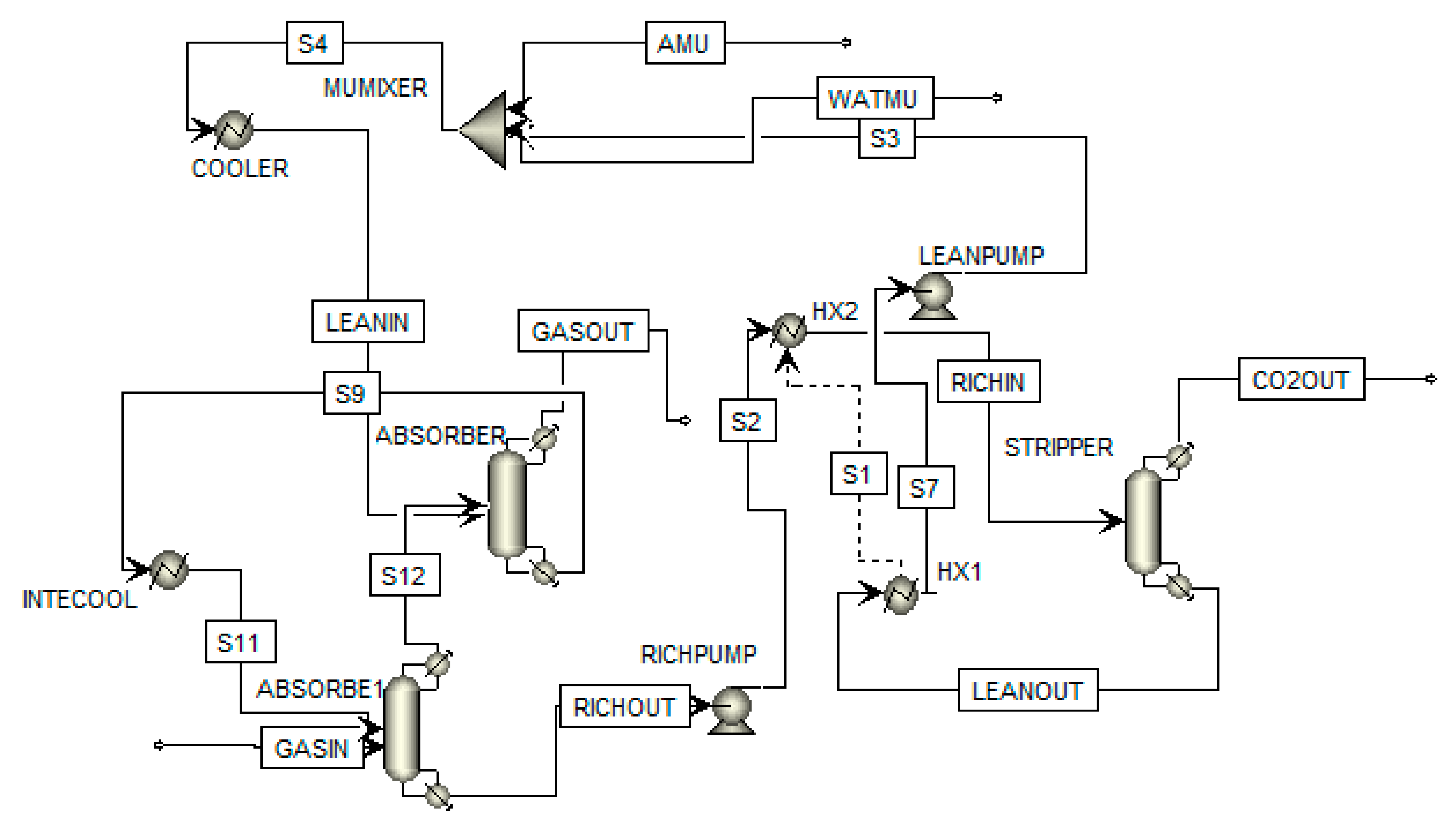
3.1. Intercooling Configuration

Absorption of CO2 from the gas streams is mostly done between temperature 40–60 °C, this is because rates of CO2 absorption for a 30 wt% amine solvent are highest in this temperature range (11). In other to control the temperature in the absorber so as to reach a higher rich CO2 loading (high absorption capacity), inter stage cooling as shown in Figure 1 is required.
In this configuration, the exothermic nature of CO2 absorption in amine present in the absorber leads to a temperature bulge and this impacts absorption negatively [36]. At the location of the T-bulge, the solvent is being extracted, cooled to 40 °C and returned to the absorber which leads to the enhancement of absorption driving force [11]. A lower temperature leads to a reduction in the absorption rates such as chemical kinetics, diffusivities, etc., while an increase in temperature favours the absorption capacity. These two operations compete with each other in the absorber. The temperature in the absorber can be controlled by adjusting the flue gas, the lean solvent temperature and flowrate coming into the absorber. Thus, this balances the temperature at either end of the absorber. With this modification, a reduction in solvent circulation rate which leads to higher absorption capacity is achieved. Hence, this process configuration enables the control of temperature within the absorber and is capable of enhancing CO2 recovery [11], which is very effective in reducing the energy requirement of a CO2 capture plant [7]. Results obtained are given in Table 3.
As shown in Table 3, lower reboiler duty and higher absorption capacity are achieved for AMP when compared with the reference; this is one of the main benefits of intercooling. This occurs due to the higher rich loading obtained from the intercooled model which leads to a lower circulation rate. Also, literature studies [37] has proven AMP to have a higher loading capacity and lower heat of reaction due to the formation of bicarbonates. The reference plant has a higher temperature bulge (63 °C) in the absorber compared to AMP-cooled (47 °C), thus having a higher heat of reaction which leads to an increment in the reboiler duty. With this intercooling, a gain of 24.5% savings in reboiler duty for AMP-cooled over the reference is achieved.

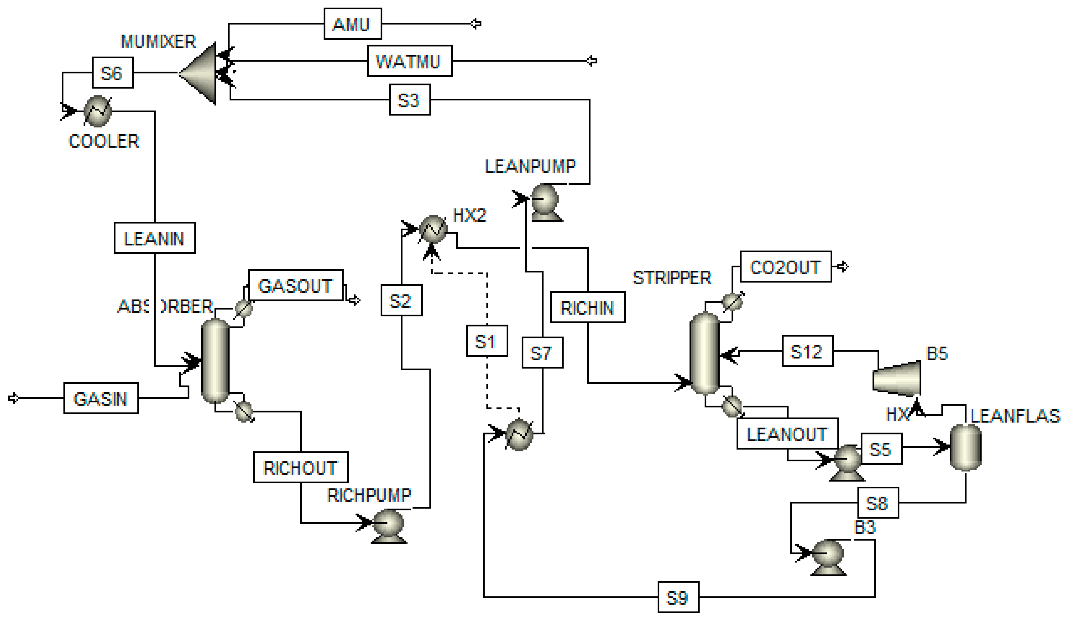
3.2. Lean Amine Flash Configuration

As shown in Figure 2, the stripper design comprises additional equipment such as a pump, compressor, and the flash drum. Additional steam is generated by flashing hot lean amine exiting the stripper close to ambient pressure, followed by the compressing of the gas stream up to the stripper pressure and re-introducing it into the stripper column [38,39]. In the flash drum present, more CO2 is desorbed by reducing the pressure in the flash drum and lean loading in the stripper out is further reduced. Thus, additional steam is generated for the AMP-based process since the gas stream is compressed at a higher pressure. Results for the lean amine flash configuration is given in Table 4.
Table 4 shows that the loading out of the stripper is further reduced and the solvent working capacity is increased for the AMP-based process with amine flash. For the AMP lean amine flash, compressing at a higher pressure, flashed vapor is heated at a higher temperature of over 140 °C, cross heat exchanger duty is further reduced and a higher stripping efficiency is achieved leading to a savings of 20.92% in reboiler duty of AMP compared to the reference. As a result of the flash, which helps to obtain saturated steam before feeding it into the stripper, hot rich amine temperature is reduced from 140 °C to 113 °C, thus leading to an increase in consumption of energy, for the reference plant as compared to the AMP lean-amine flash.

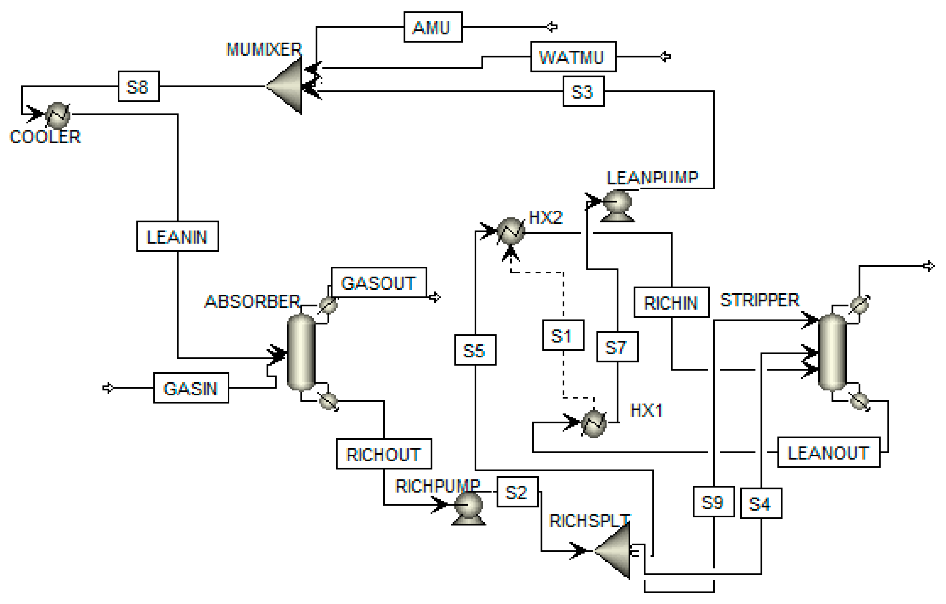
3.3. Rich Split Configuration

The process in Figure 3 involves the splitting of the rich stream where the split entering the top of the stripping column stays unheated. It has the capability of pre-stripping the cold rich solvent entering at the top of the stripping column; this can be attained due to the vapor released from the rich solvent steam which moves up the stripping column. This helps to thermally regenerate less solvent, thereby reducing regeneration energies [11]. Hence, this configuration process is beneficial for lean loadings above 0.15 mol/mol and this reduces the energy required for regeneration [11].
In the configuration obtained in a study by Cousins et al. [11], 30% of the cold rich solvent was split to the top of the column with a condensate packing height of 1.12 m and a minimum reboiler duty of 97.8 kW was obtained which was about 10.3% higher savings than the reference case. The reason for this is that the reboiler duty achieves a combination of four functions: (i) providing sensible heat to the rich solvent to increase its temperature to the specified reboiler temperature, in which some heat is attained in the lean/rich heat exchanger [11]. (ii) evaporating water in the reboiler, which acts as the stripping agent, aiding the CO2 removal from the solvent. Thus, steam released will replace steam generated in the reboiler, this is because the generation of steam within the column reduces the operating CO2 partial pressure below that of the partial pressure in the column, enabling stripping to occur. (iii) Providing heat to reverse the absorption reaction in the absorber, which is in theory, equal to that released due to the exothermic reactions and (iv) providing heat to liberate dissolved CO2 out of the solvent. Depending on the function which is most dominant under a given set of conditions, the reboiler duty will adjust accordingly to maintain the required stripping rate. The study also revealed that the possibility of obtaining a higher CO2 flashing will allow the further release of CO2 in the upper stages of the stripping column and give additional benefits [11].
It should be noted however that the efficiency of the lean/rich heat exchanger will have a significant effect on the results of this process modification. The objective of the lean/rich exchanger is energy conservation. The energy available from the lean amine stream is transferred to the rich amine prior to introducing the rich amine to the stripper. This energy transfer results in a decreased energy requirement for the stripper as observed in the results presented in Table 5.
During the operation considered here, the solvent split fraction was found to have a significant effect on the temperature approach achieved through the lean/rich heat exchanger. As more of the cold rich solvent is split to the top of the column, the lower flowrate through the heat exchanger means that the hot rich solvent can be raised to higher temperatures. The vapor fraction in the hot rich solvent will increase, providing more steam for pre-stripping, which reduces the reboiler duty, as shown in Table 4. Thus, the reboiler duty slightly reduces from 4.77 kW to 4.73 kW for rich split configuration as compared to the reference plant.

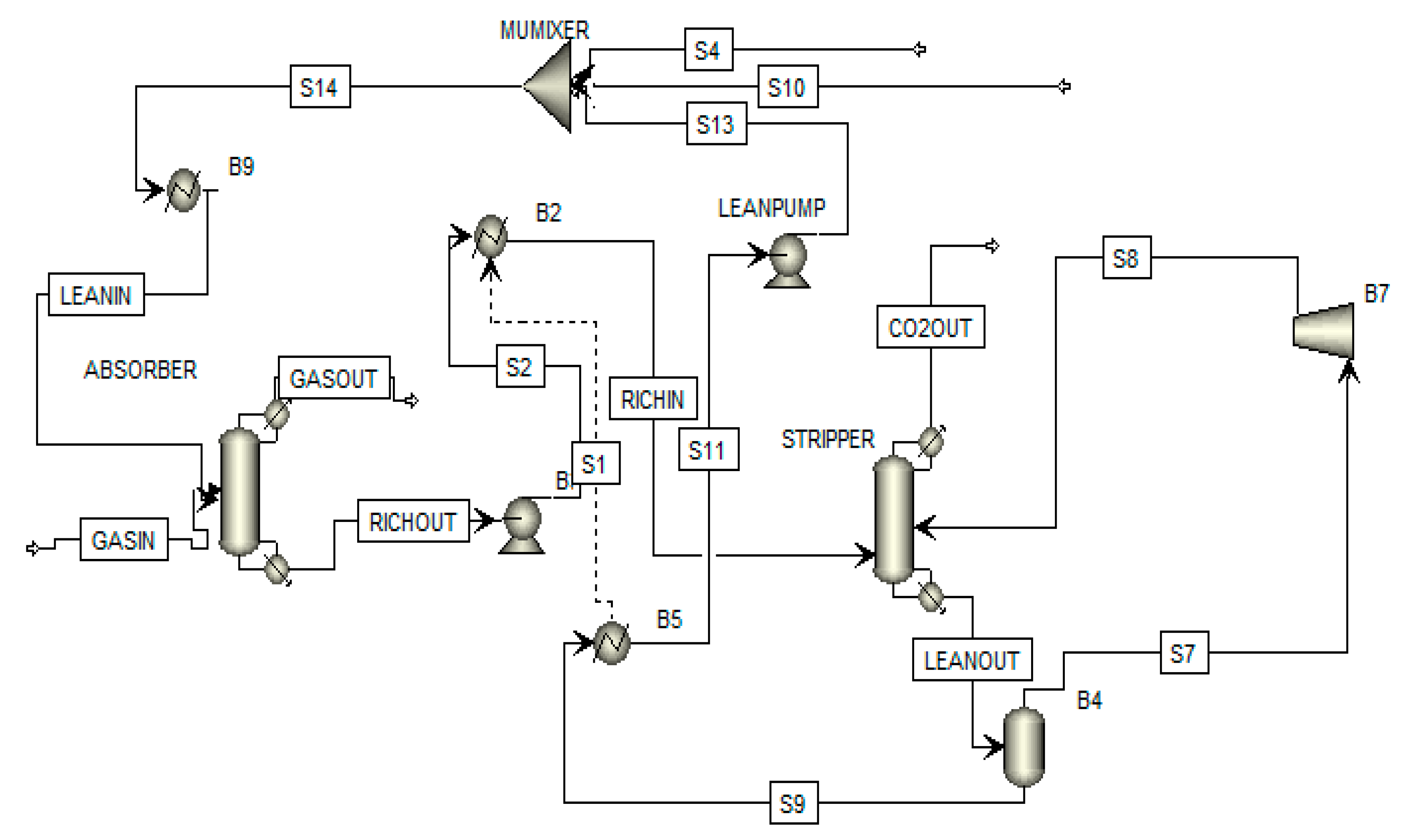
3.4. Vapor Recompression

This process modification as shown in Figure 4 involves the extraction of steam from a part of the stripping column, which is recompressed and re-introduced into the regenerator. This operation turns mechanical energy into thermal energy to provide more stripping steam [11]. Hence, this configuration works by providing an additional source of stripping steam for the column, as this lowers the thermal input required by the stripper. The vapor is compressed to five times the operating pressure of the stripping column, before being separated with the condensate recycled back to the stripper [11]. Although this process configuration reduces the reboiler duty, it leads to a corresponding increase in the power requirement due to the addition of the compression stages [11]. Thus, in this study, one expansion stage is used to make comparison easier.
As shown in Table 6, 59.5% savings in reboiler duty is obtained for the AMP-based plant compared to the reference case. For the vapor recompression configuration, additional stripping steam is generated, this is as a result of the higher pressure which leads to a higher temperature and enables the lean solvent flash pressure drop to increase. Also observed is the reduced heat exchanger duty obtained for the vapor recompression flowsheet, this is because lean solvent temperature increases which lead to a higher stripping efficiency.

3.5. Rich Split with Intercooling

As mentioned earlier, splitting the rich stream by 20–30% as recommended in the literature [11], can increase the absorption capacity which brings about the energy savings for the stripper design. In addition, the rich split modification requires minimal additional equipment. Furthermore, cooling at different stages in the absorber column has a significant effect in reducing the reboiler duty. Thus, with multiple alterations, reboiler duty can be further reduced [40]. Also, since the highest and lowest savings in the reboiler duty for intercooling and rich split configurations respectively, were obtained in this study, a combination of rich split and intercooling configurations will be necessary, to observe if any benefit can be obtained, and to enable further reduction in reboiler duty as shown in Figure 5.
Simulation results are reported in Table 7 below, the multiple measures taken (rich split with intercooling) for the AMP-based process led to the energy savings of about 88.5% higher than the reference case. Thus, comparing the five different flowsheeting configurations, the rich split with intercooling configuration gave the best performance. This is in accordance with the literature [13].

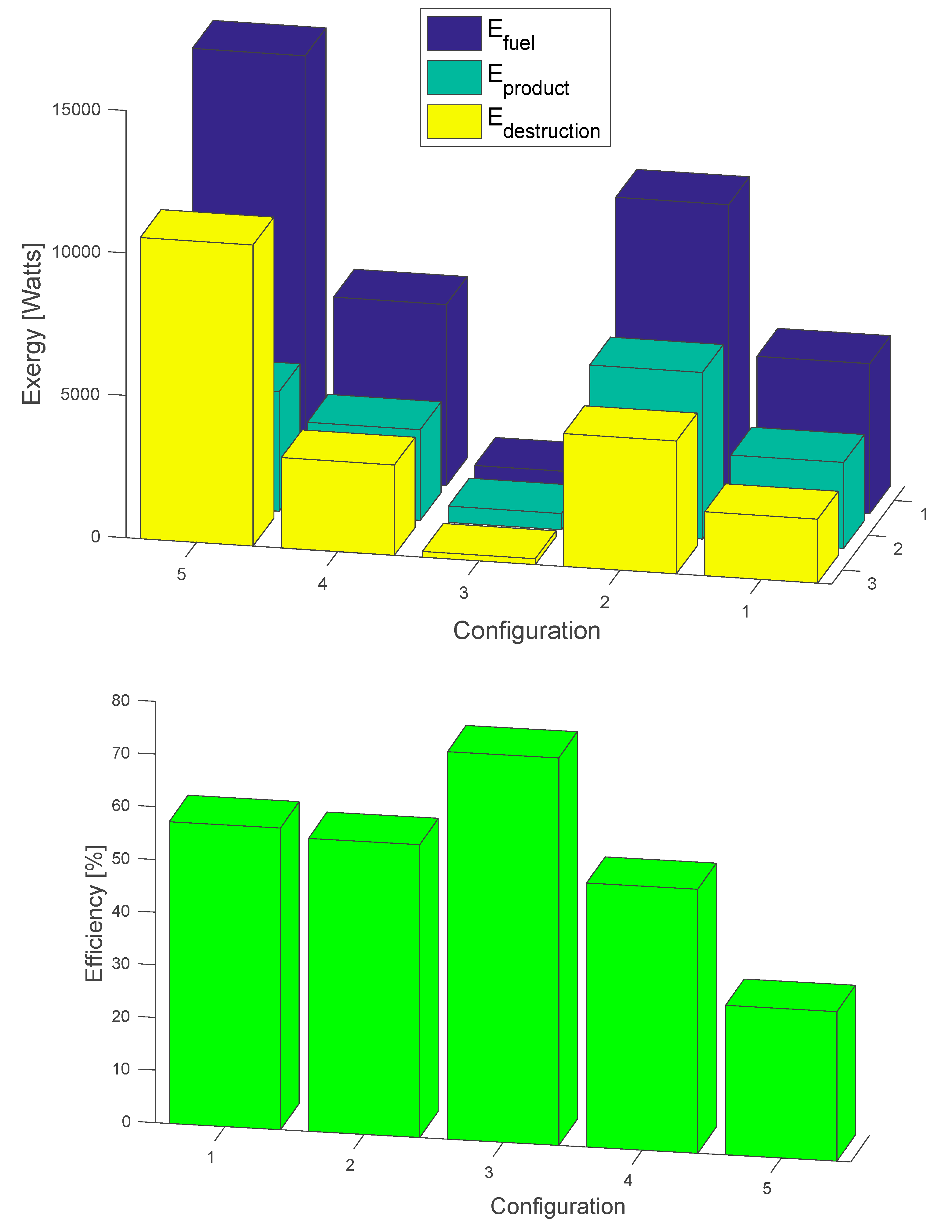
4. Exergy Analysis for the Flowsheeting Configurations

Table 8 below shows the total exergy analysis and performance evaluation of the different flowsheeting configurations. Results show that the rich split with intercooling and vapor recompressions configurations gave the best and worst exergetic performances respectively as compared to the other configurations. Also, as compared to the reference plant which is presented in Table 2, two configurations (rich split with intercooling and intercooling alone and gave higher exergy efficiency than the reference case. While lean amine flash, rich split alone and vapor recompressions gave lower exergy efficiencies as compared to the reference plant. A reason for the low efficiencies could be that, the more efficient the configurations (based on the reboiler duty), the less outlet for exergy losses. Furthermore, Figure 6, shows the efficiency pecentage and the amount of exergy for the different configurations. As clearly seen, the rich split with interccoling configuration, gave the highest exergy efficiency amd the lowest exergy destruction.

5. Conclusions

In this study, the exergy analysis of the AMP PCC process and its flowsheeting configurations have been evaluated. The operating parameters for the rate-based AMP model present in Aspen Plus® software were used to describe the PCC process. The conventional exergy analysis performed provides an evaluation of energy consumption the CO2 capture plant from the thermodynamic point of view, and also evaluates the reduction of the exergy destruction. The pump and stripper subsystems of the AMP-based capture plant had the highest exergy destruction, and the cross-heat exchanger subsystem gave the lowest exergy destruction performance.
Several configurations were proposed in the literature to reduce energy requirements in the amine-based CO2 capture plant, these configurations at atmospheric pressure have been simulated in Aspen Plus® software. Flowsheeting configurations considered in this study include intercooling, lean-amine flash, rich split, vapor recompression and the rich split with intercooling configurations. Results show that the combination configuration (rich split with intercooling) had the highest savings (88.5%) in reboiler duty as compared to the reference AMP-based plant, and the other flowsheeting configurations. Furthermore, exergy analysis performed showed that the rich split with intercooling configuration had the highest exergy efficiency of 74%, followed by the intercooling configuration with 57% exergy efficiency, and that of the reference AMP plant was obtained to be 56%. The other configurations considered in the study had exergy efficiencies lower than that of the reference plant. This study has shown that some of the flowsheeting configurations can reduce the heat required for regeneration, and others can both reduce reboiler duty and at the same time increase the exergy efficiency. Thus, the flowsheeting configurations have significant improvements in the plant performance and may lead to cost reduction for the amine-based CO2 capture technology. Although the additional equipment for each configuration may incur extra cost, economic analysis is therefore required to ascertain if any cost benefits can be obtained with flowsheeting configurations for the AMP-based PCC process.

Author Contributions

E.O.—methodoogy and writing original draft; A.M.A.—supervision, review and editing; S.G.N.—writing, review and editing; O.O.—review and editing; V.E.—review and editing.

Funding

This research received no external funding.

Conflicts of Interest

The authors declare no conflict of interest.

References

  1. Chalmers, H.; Gibbins, J. Initial evaluation of the impact of post-combustion capture of carbon dioxide on supercritical pulverised coal power plant part load performance. Fuel 2007, 86, 2109–2123. [Google Scholar] [CrossRef]
  2. Rubin, E.S.; Chen, C.; Rao, A.B. Cost and performance of fossil fuel power plants with CO2 capture and storage. Energy Policy 2007, 35, 4444–4454. [Google Scholar] [CrossRef]
  3. Davison, J. Performance and costs of power plants with capture and storage of CO2. Energy 2007, 32, 1163–1176. [Google Scholar] [CrossRef]
  4. Jassim, M.S.; Rochelle, G.T. Innovative absorber/stripper configurations for CO2 capture by aqueous monoethanolamine. Ind. Eng. Chem. Res. 2006, 45, 2465–2472. [Google Scholar] [CrossRef]
  5. Reddy, S.; Scherffius, J.; Freguia, S.; Roberts, C. Fluor’s Econamine FG Plus SM Technology. In Proceedings of the Second Annual Conference on Carbon Sequestration, Alexandria, VA, USA, 6 May 2003. [Google Scholar]
  6. Leites, I.L.; Sama, D.A.; Lior, N. The theory and practice of energy saving in the chemical industry: Some methods for reducing thermodynamic irreversibility in chemical technology processes. Energy 2003, 28, 55–97. [Google Scholar] [CrossRef]
  7. Karimi, M.; Hillestad, M.; Svendsen, H.F. Investigation of intercooling effect in CO2 capture energy consumption. Energy Procedia 2011, 4, 1601–1607. [Google Scholar] [CrossRef]
  8. Aroonwilas, A.; Veawab, A. Integration of CO2 capture unit using single-and blended-amines into supercritical coal-fired power plants: Implications for emission and energy management. Int. J. Greenh. Gas Control. 2007, 1, 143–150. [Google Scholar] [CrossRef]
  9. Reddy, S.; Scherffius, J.; Gilmartin, J.; Freguia, S. Improved split flow apparatus. Patent No. WO 2004005818 A2, 2004. [Google Scholar]
  10. Eisenberg, B.; Johnson, R.R. Amine Regeneration Process. U.S. Patent 4,152,217A1, 1 May 1979. [Google Scholar]
  11. Cousins, A.; Wardhaugh, L.T.; Feron, P.H. Preliminary analysis of process flow sheet modifications for energy efficient CO2 capture from flue gases using chemical absorption. Chem. Eng. Res. Des. 2011, 89, 1237–1251. [Google Scholar] [CrossRef]
  12. Ahn, H.; Luberti, M.; Liu, Z.; Brandani, S. Process configuration studies of the amine capture process for coal-fired power plants. Int. J. Greenh. Gas Control. 2013, 16, 29–40. [Google Scholar] [CrossRef] [Green Version]
  13. Sharma, M.; Quadii, A.; Khalilpouri, R. Modeling and analysis of process configurations for solvent-based post-combustion carbon capture. Asia-Pac. J. Chem. Eng. 2015, 10, 764–780. [Google Scholar] [CrossRef]
  14. Lars, E.O.; Terje, B.; Christian, B.; Sven, K.B.; Marius, F. Optimization of configurations for amine based CO2 absorption using Aspen HYSYS. 7th Trondheim CCS Conference, TCCS-7. Energy Procedia 2014, 51, 224–233. [Google Scholar]
  15. Liang, Z.; Gao, H.; Rongwong, W.; Na, Y. Comparative studies of stripper overhead vapor integration-based configurations for post-combustion CO2 capture. Int. J. Greenh. Gas Control. 2015, 34, 75–84. [Google Scholar] [CrossRef]
  16. Jaeheum, J.; Yeong, S.J.; Ung, L.; Youngsub, L.; Chonghun, H. New Configuration of the CO2 Capture Process Using Aqueous Monoethanolamine for Coal-Fired Power Plants. Ind. Eng. Chem. Res. 2015, 54, 3865–3878. [Google Scholar]
  17. Gabrielsen, F.H. Exergy analysis of alkanolamine-based CO2 removal unit with Aspen Plus. Energy 2004, 29, 1241–1248. [Google Scholar] [CrossRef]
  18. Lara, Y.; Martinez, A.; Lisbona, P.; Bolea, I.; Gonzalez, A.; Romeo, L.M. Using the second law of thermodynamic to improve CO2 capture systems. Energy Procedia 2011, 4, 1043–1050. [Google Scholar] [CrossRef]
  19. Olaleye, A.K.; Wang, M.; Kelsall, G. Steady state simulation and exergy analysis of supercritical coal-fired power plant with CO2 capture. Fuel 2015, 151, 57–72. [Google Scholar] [CrossRef]
  20. Valenti, G.; Bonalumi, D.; Macchi, E. Energy and exergy analyses for the carbon capture with the Chilled Ammonia Process (CAP). Energy Procedia 2009, 1, 1059–1066. [Google Scholar] [CrossRef] [Green Version]
  21. Alatiqi, I.; Sabri, M.F.; Bouhamra, W.; Alper, E. Steady-state rate based modelling for CO2 amine absorption—Desorption systems. Gas Sep. Purif. 1994, 8, 3–11. [Google Scholar] [CrossRef]
  22. Aboudheir, A.; Tontiwachwuthikul, P.; Idem, R. Rigorous model for predicting the behavior of CO2 absorption into AMP in packed-bed absorption columns. Ind. Eng. Chem. Res. 2006, 45, 2553–2557. [Google Scholar] [CrossRef]
  23. Gabrielsen, J.; Svendsen, H.F.; Michelsen, M.L.; Stenby, E.H.; Kontogeorgis, G.M. Experimental validation of a rate-based model for CO2 capture using an AMP solution. Chem. Eng. Sci. 2007, 62, 2397–2413. [Google Scholar] [CrossRef]
  24. Gabrielsen, J.; Michelsen, M.L.; Stenby, E.H.; Kontogeorgis, G.M. Modeling of CO2 absorber using and AMP solution. AIChE J. 2006, 52, 3443–3451. [Google Scholar] [CrossRef]
  25. Afkhamipour, M.; Mofarahi, M. Comparison of rate-based and equilibrium-stage models of a packed column for post-combustion CO2 capture using 2-amino-2-methyl-1-propanol (AMP) solution. Int. J. Greenh. Gas Control 2013, 15, 186–199. [Google Scholar] [CrossRef]
  26. Dash, S.K.; Samanta, A.N.; Bandyopadhyay, S.S. Simulation and parametric study of post-combustion CO2 capture process using (AMP + PZ) blended solvent. Int. J. Greenh. Gas Control 2014, 21, 130–139. [Google Scholar] [CrossRef]
  27. Kvamsdal, H.M.; Chikukwa, A.; Hillestad, M.; Zakeri, A.; Einbu, A. A comparison of different parameter correlation models and the validation of an MEA-based absorber model. Energy Procedia 2011, 4, 1526–1533. [Google Scholar] [CrossRef] [Green Version]
  28. Osagie, E.; Biliyok, C.; Di Lorenzo, G.; Hanak, D.; Manovic, V. Techno-economic evaluation of the 2-amino-2-methyl-1-propanol (AMP) process for CO2 capture from natural gas combined cycle power plant. Int. J. Greenh. Gas Control 2018, 70, 45–56. [Google Scholar] [CrossRef]
  29. MacDowell, N.; Florin, N.; Buchard, A.; Hallett, J.; Galindo, A.; Jackson, G. An overview of CO2 capture technologies. Energy Environ. Sci. 2010, 3, 1645. [Google Scholar] [CrossRef]
  30. Mahamud, R.; Khan, M.M.K.; Rasul, M.G.; Leinster, M.G. Exergy Analysis and Efficiency Improvement of a Coal Fired Thermal Power Plant in Queensland. In Thermal Power Plants—Advanced Applications; IntechOpen Limited: London, UK, 2013. [Google Scholar] [Green Version]
  31. Aspen Technology. Rate-Based Model of the CO2 Capture Process by AMP Using Aspen Plus; Aspen Technology, Inc.: Cambridge, MA, USA, 2008. [Google Scholar]
  32. Tsatsaronis, G.; Cziesla, F. Strengths-and-Limitations-of-Exergy-Analysis; Institute of Energy Engineering: Berlin, Germany, 1999; Volume 69, pp. 93–100. [Google Scholar]
  33. Sherman, B.J. Thermodynamic and Mass Transfer Modelling of Aqueous Hindered Amines for Carbon Dioxide Capture. Ph.D. Dissertation, University of Texas, Austin, TX, USA, 2016. [Google Scholar]
  34. Herrmann, J. Conversion of Experimental Data for Process Modelling of Novel Amine CO2 Capture Solvents. Master’s Thesis, Norwegian University of Science and Technology, Trondheim, Norway, 2014. [Google Scholar]
  35. Yang, Y. Comprehensive exergy-based evaluation and parametric study of a coal-fired ultra-supercritical power plant. Appl. Energy 2013, 112, 1087–1099. [Google Scholar] [CrossRef]
  36. Kvamsdal, H.M.; Rochelle, G.T. Effects of the temperature bulge in CO2 absorption from flue gas by aqueous monoethanolamine. Ind. Eng. Chem. Res. 2008, 47, 867–875. [Google Scholar] [CrossRef]
  37. Anthony, J.L. Carbon dioxide: Generation and capture. In Energy and Environmental Impacts Related to Sustainability Seminar; Kansas State University: Manhattan, KS, USA, 2006. [Google Scholar]
  38. Woodhouse, S.; Rushfeldt, P. Improved Absorbent Regeneration. Patent No. WO2008/063079 A2, 29 May 2008. [Google Scholar]
  39. Reddy, S.; Gilmartin, J.; Francuz, V. Integrated Compressor/Stripper Configurations and Methods. U.S. Patent 2009/0205946 A1, 20 August 2009. [Google Scholar]
  40. Le Moullec, Y.; Kanniche, M. Screening of flowsheet modifications for an efficient monoethanolamine (MEA) based post-combustion CO2 capture. Int. J. Greenh. Gas Control. 2011, 5, 727–740. [Google Scholar] [CrossRef]
Figure 1. Intercooling Configuration [11].
Processes 07 00391 g001
Figure 2. Lean amine flash modification [12].
Processes 07 00391 g002
Figure 3. Rich split modification [11].
Processes 07 00391 g003
Figure 4. Vapor recompression modification [11].
Processes 07 00391 g004
Figure 5. Rich split with intercooling configuration.
Processes 07 00391 g005
Figure 6. Summary Results of Exergy Analysis for the Different Configurations. For the horizontal “Configuration” axis, 1. Intercooling 2. Rich Split 3. Rich Split with Intercooling 4. Lean Amine Flash 5. Vapor Recompression.
Processes 07 00391 g006
Table 1. Summary of representative past works on flowsheeting configurations for CO2 capture plants.
Author(s)Detail of StudySolventExergy Analysis
Leites et al. [6]Evaluated intercooler at 40–80 °C, operation at 40 °C gave a maximum effect on reboiler duty using monoethanolamine (MEA) MEANo
Karimi et al. [7]Evaluated intercooling effect. The optimal location for intercooling was 1/4th to 1/5th of the height of the column from the bottom, nearly 3% savings in reboiler energy. MEANo
Aroonwilas and Veawab [8]Evaluated intercooling design. Removal of liquid done at 1/5th of column height from the bottom. Cooling at 45 °C resulted in 10% energy savings in the reboiler. MEANo
Reddy et al. [9]Evaluated lean amine flash configuration. Hot lean amine temperature reduced from 120 to 103 °C, the low temperature, however, increases the energy consumption in the stripper. MEANo
Eisenberg and Johnson [10]Evaluated rich split configuration resulting in 7.1% reboiler duty savings over reference case. MEANo
Cousins et al. [11]Reviewed fifteen flowsheeting configurations, these include multi-component columns, inter-stage temperature control, heat-integrated stripping column, split flow process, vapor recompression, matrix stripping, heat integration. Results showed significant energy savings.MEANo
Ahn et al. [12]Evaluated ten different configurations capture plants, this included the multiple alterations (absorber intercooling combined with condensate evaporation and lean amine flash). The multiple strategies achieved a greater reduction in the energy requirement reducing steam consumption by up to 37% when compared to the simple absorber/stripper configurations.MEANo
Sharma et al. [13]Reviewed and assessed the advantages of fourteen different flow sheeting configurations. Results showed pump-around was more beneficial than intercooling.MEANo
Lars et al. [14]Evaluated and compared different configurations; vapor recompression with split stream gave the best reduction of 11% compared to the conventional.MEANo
Liang et al. [15]Five different flow sheeting configurations studied, the new innovation was the combination of split flow with overhead exchanger and improved split flow with vapor recompression These innovations decreased equivalent work by 17.21% and 17.52% respectivelyMEANo
Jung et al. [16]Evaluated rich vapor recompression and cold solvent split. Results showed that reboiler heat was reduced from 3.44 MJ/kg CO2 to 2.75 MJ/kg CO2.MEANo
Geuzebroek [17], Lara et al. [18], Olaleye et al. [19]Exergy analysis of CO2 capture plantMEAYes
Valenti et al. [20]Exergy analysis of CO2 capture plantAmmoniaYes
Table 2. Conventional exergy analysis of the AMP-based CO2 capture plant.
E f u e l ( n )
(Watts)
E p r o d u c t ( n )
(Watts)
E d e s t r u c t i o n ( n )
(Watts)
E n
(%)
Absorber45.1927.0218.1759.79
Stripper5085.564224.59860.9783.07
Pump393.27389.293.9898.99
Cooler1037.07307.0730.0629.60
Heat exchanger4174.621037.073137.5524.84
Total10,735.75984.984750.7255.75
Table 3. Results for intercooling configuration.
Rich Loading (mol/mol)Absorber (ABS) Capacity (mol/mol)Reboiler Duty (kW)ABS Temp (°C)
Reference0.3880.1234.7763.07
AMP-cooled0.5030.1733.6047.11
Table 4. Results for lean amine flash configuration.
Loading of Lean Out (mol/mol)Reboiler Duty (kW)Cross-Heat Exchanger Duty (kW)
Reference0.2654.7717.46
AMP-lean amine flash0.2522.7910.92
Table 5. Results for rich split configuration.
Split-Fraction (%)Reboiler Duty (kW)Cross Heat Exchanger Flowrate (kg/s)Cross Heat Exchanger Duty (kW)
Reference04.770.1008917.46
AMP-rich Split304.70.0998917.30
Table 6. Results for vapor recompression.
Reboiler Duty (kW)Cross-Heat Exchanger Duty (kW)
Reference plant4.7717.46
AMP Vap-Recompression1.935.69
Table 7. Results for rich split and intercooling
Reboiler Duty (kW)Cross-Heat Exchanger Flowrate (kg/s)Cross-Heat Exchanger Duty (W)
Reference4.770.1008917.46
AMP Rich split0.552.55 × 10−45.30
Table 8. Summary of Exergy Analysis for the Different Configurations.
ConfigurationsEfuel (Watts)Eproduct (Watts)Edestruction (Watts)Eeff (%)
Intercooling5261.333015.672245.6657.32
Rich split10,515.445851.374664.0755.65
Rich slit + intercooling780.11573.87206.2373.56
Lean amine flash6360.783189.953170.8350.15
Vapor recompression14,767.74197.0710,570.6528.42

