Modeling of a Double Effect Heat Transformer Operating with Water/Lithium Bromide


Abstract
:1. Introduction
1.1. Theoretical Investigations about Advanced Heat Transformers
1.2. Experimental Investigations
2. System Description
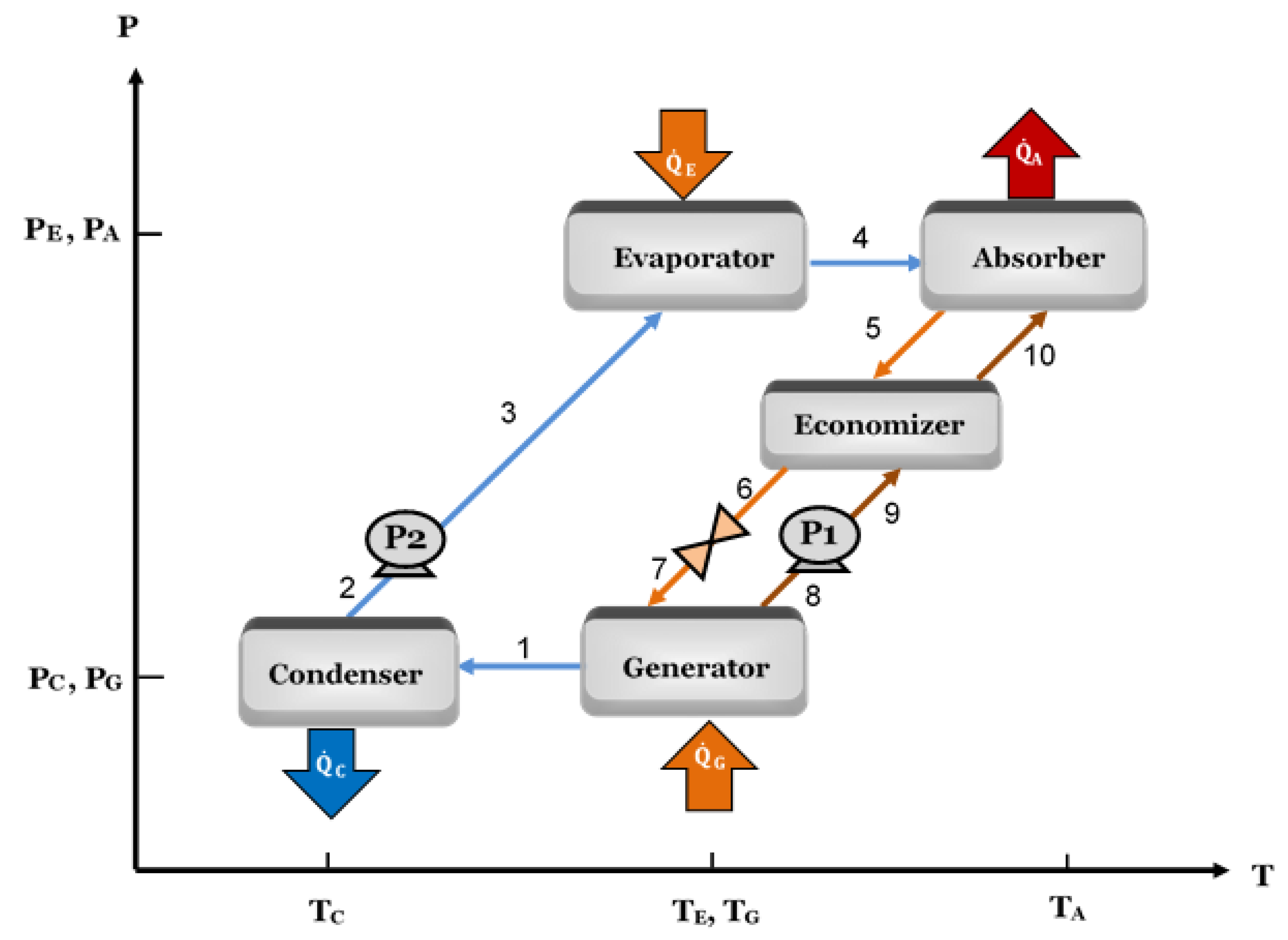
2.1. Single-Stage Heat Transformer
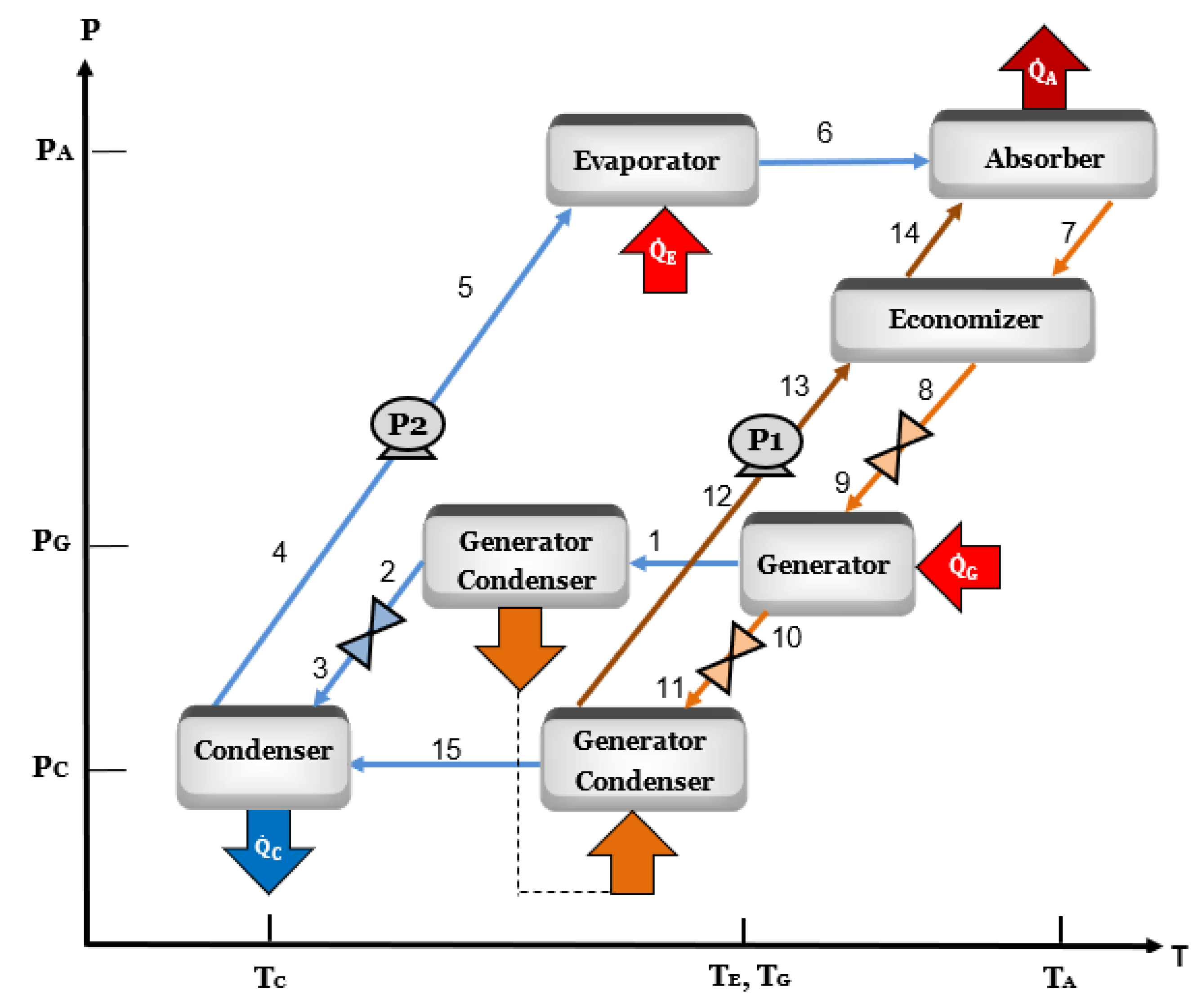
2.2. Double-Effect Heat Transformer
3. Mathematical Model
3.1. Assumptions
- In order to calculate the properties of the system, thermodynamic equilibrium conditions are considered.
- The cycle works in steady-state conditions.
- A rectifier is not required since there is not absorbent evaporation throughout the cycle.
- The same source is used to supply the heat to both the generator and the evaporator.
- Heat losses from the heat transformer components are considered negligible.
- Refrigerant saturation points are assumed at the exit of the condenser, the evaporator, and the generator/condenser.
- Saturation conditions for the solution are assumed at the exit of the absorber, the generator, and the generator/condenser.
- Pressure losses due to friction are neglected.
- The pumping process is isentropic.
- The throttling process in the valves is isenthalpic.
3.2. Main Equations
3.3. Input Data
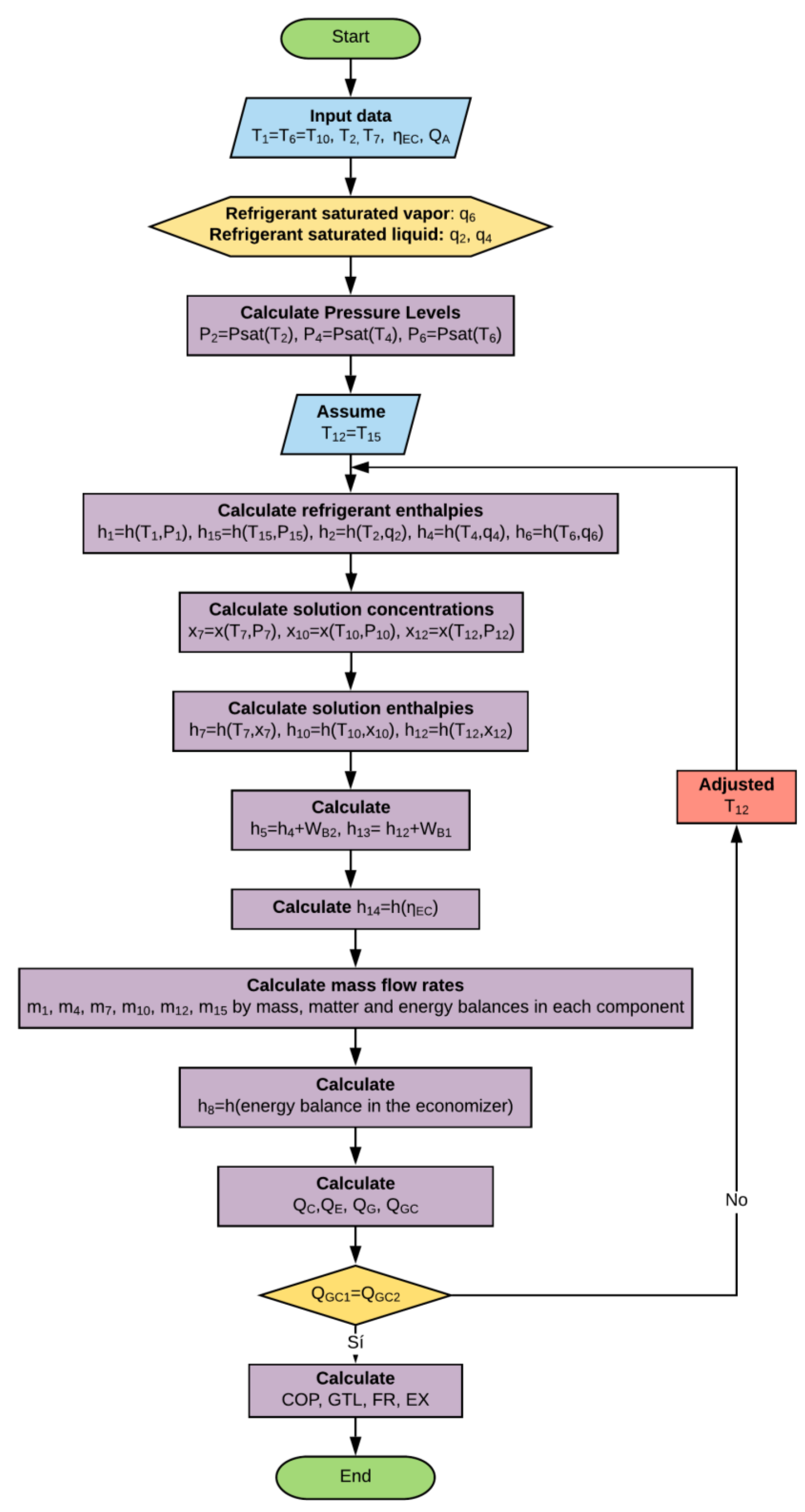
3.4. Algorithm
4. Results
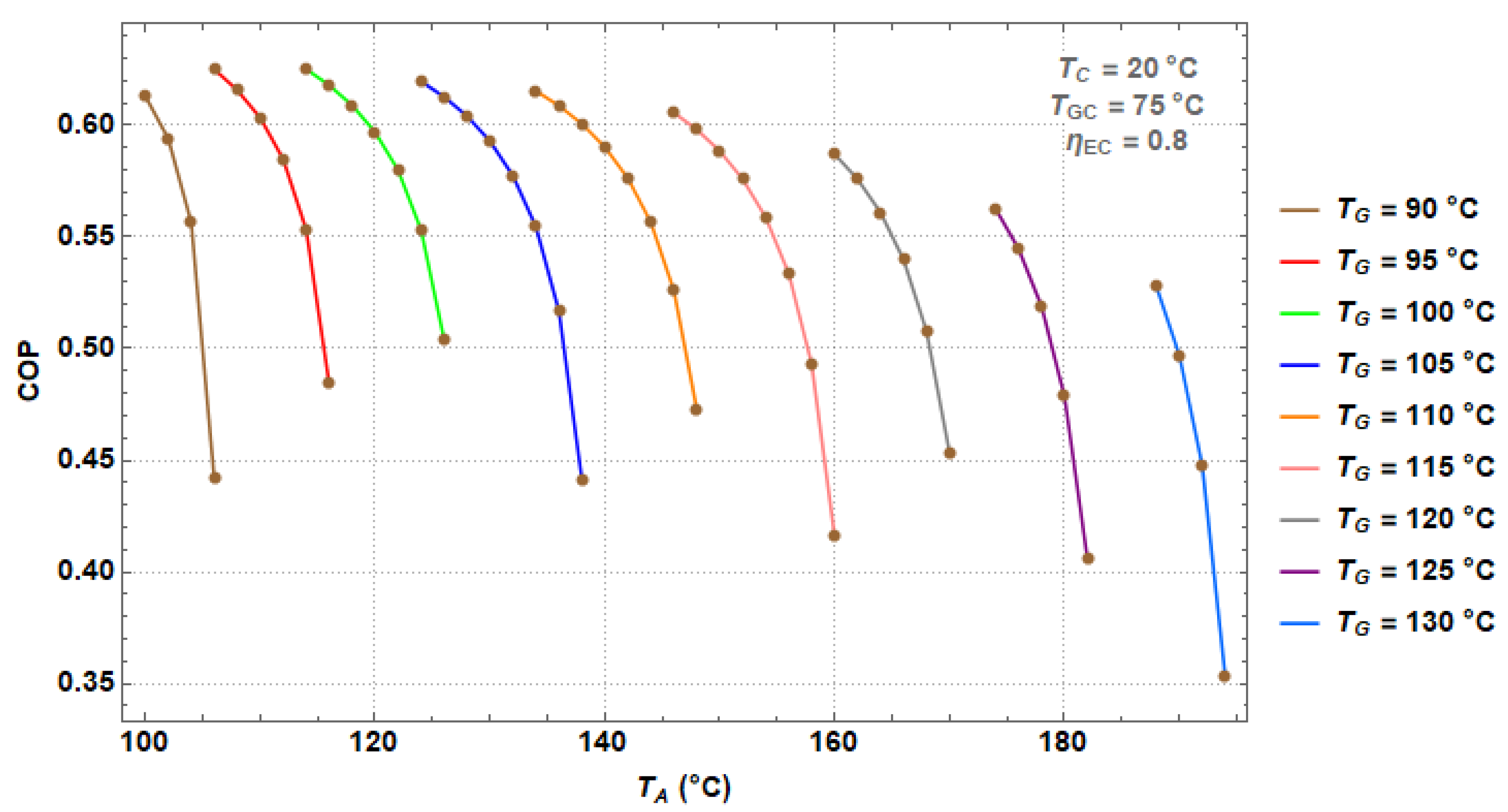
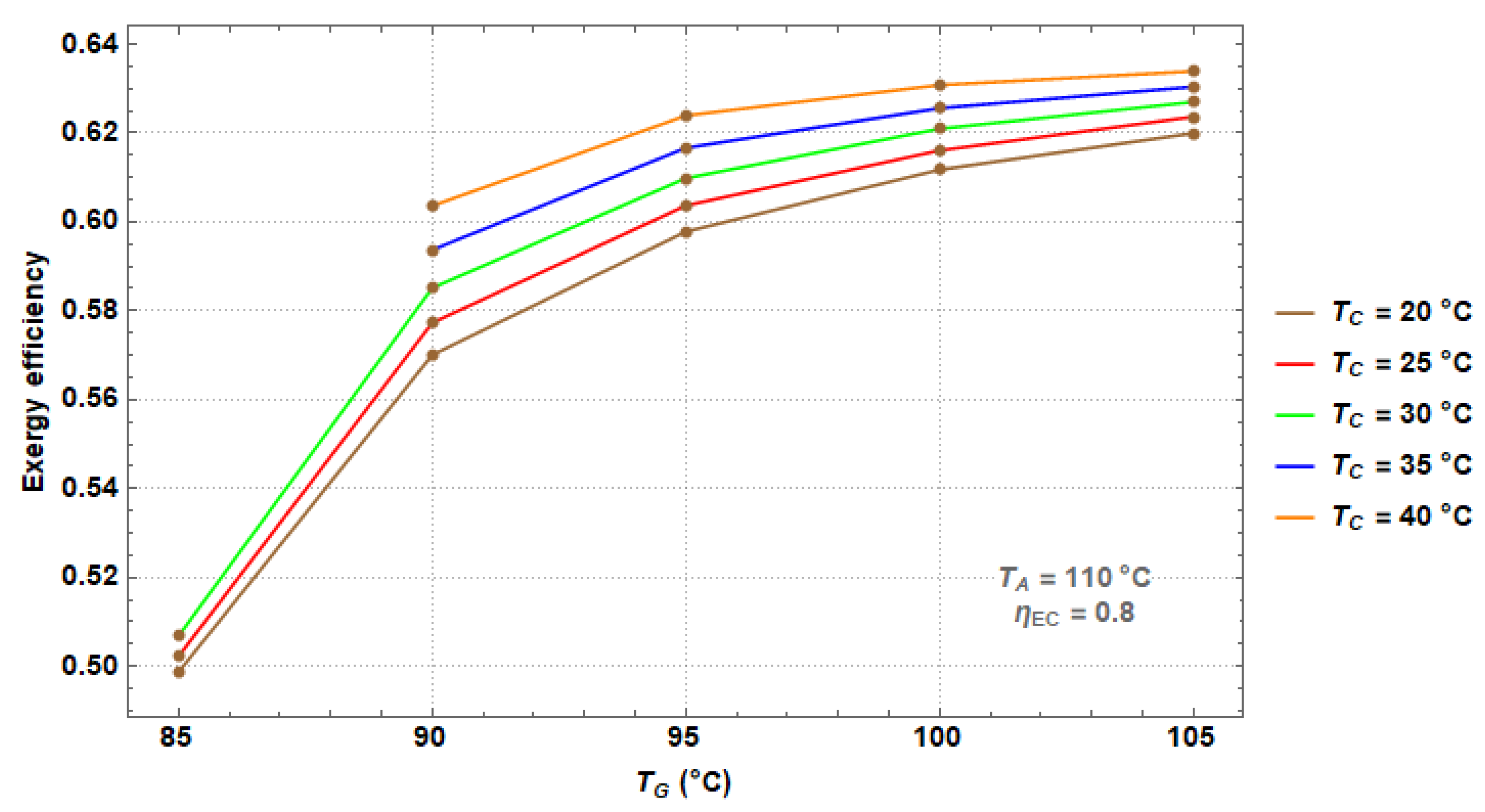
4.1. Modeling of the DEHT
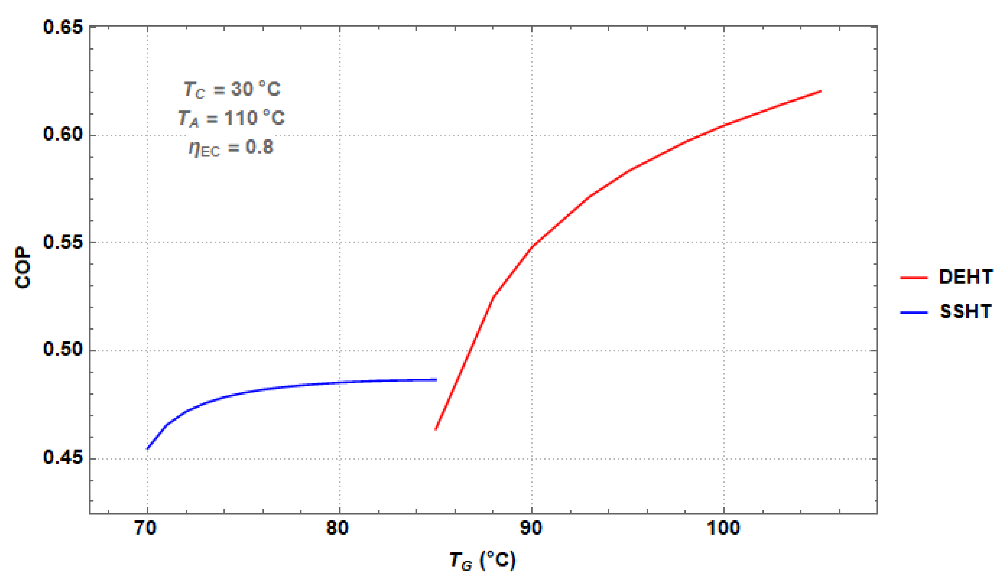
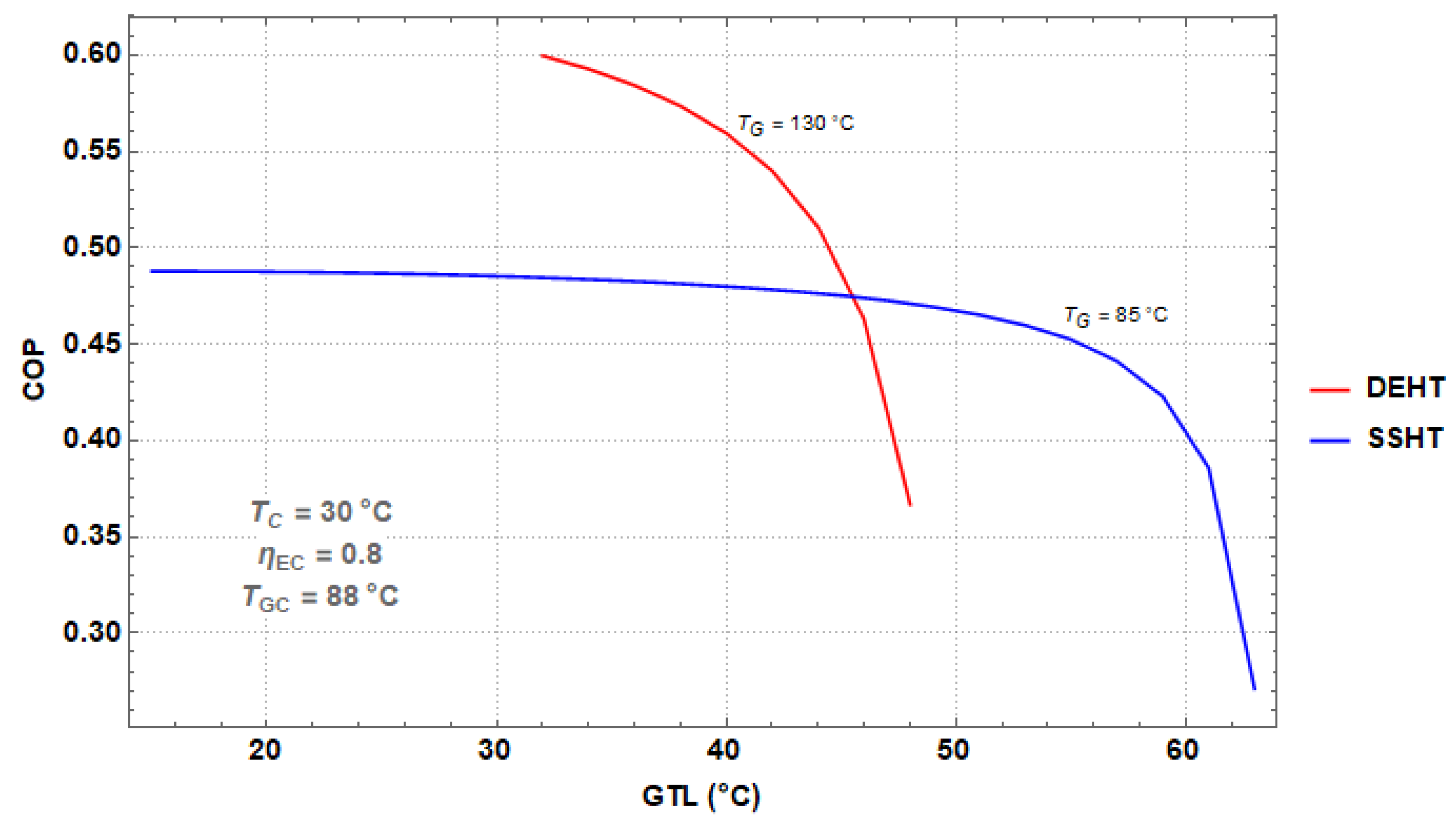
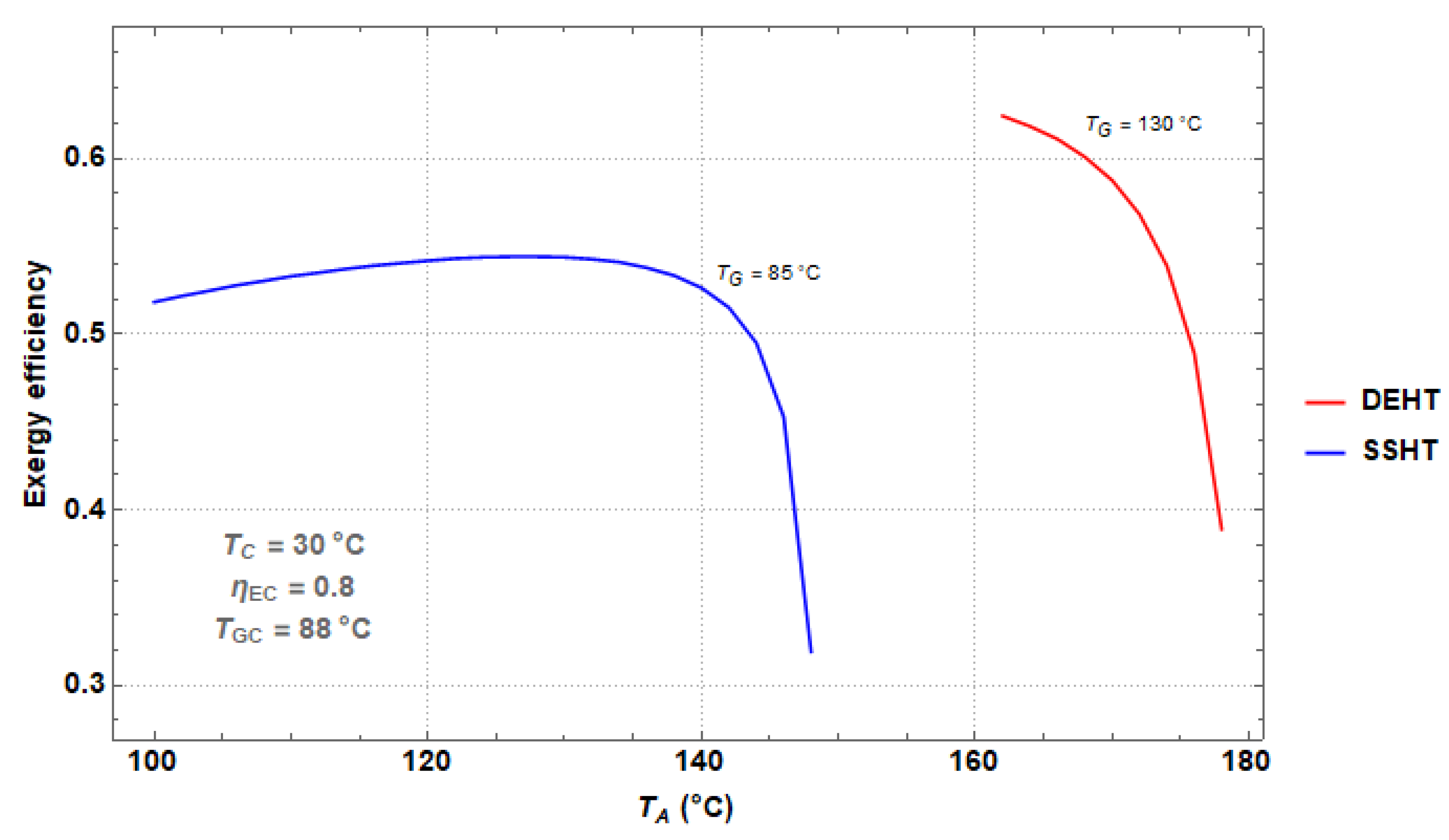
4.2. Comparison of the Performance between the SSHT and the DEHT
5. Conclusions
Author Contributions
Conflicts of Interest
Nomenclature
| AHT | Absorption Heat Transformer |
| COP | Coefficient of Performance (dimensionless) |
| DAHT | Double Absorption Heat Transformers |
| DEHT | Double Effect Heat Transformer |
| FR | Flow Ratio |
| GTL | Gross Temperature Lift (°C) |
| Specific enthalpy | |
| HT | Heat Transformer |
| Mass flow rate | |
| Effectiveness (dimensionless) | |
| ORC | Organic Rankine Cycle |
| Pressure (bar) | |
| Thermal power (kW) | |
| q | Vapor quality (dimensionless) |
| SSHT | Single-Stage Heat Transformer |
| T | Temperature (°C) |
| Mechanical power (kW) | |
| x | LiBr concentration (dimensionless) |
Subscripts
| A | absorber |
| C | condenser |
| E | evaporator |
| EC | economizer |
| G | generator |
| GC | generator-condenser |
| P | pump |
References
- Parham, K.; Khamooshi, M.; Tematio, D.B.K.; Yari, M.; Atikol, U. Absorption heat transformers—A comprehensive review. Renew. Sustain. Energy Rev. 2014, 34, 430–452. [Google Scholar] [CrossRef]
- Donnellan, P.; Cronin, K.; Byrne, E. Recycling waste heat energy using vapour absorption heat transformers: A review. Renew. Sustain. Energy Rev. 2015, 42, 1290–1304. [Google Scholar] [CrossRef]
- Rivera, W.; Best, R.; Cardoso, M.J.; Romero, R.J. A review of absorption heat transformers. Appl. Therm. Eng. 2015, 91, 654–670. [Google Scholar] [CrossRef]
- Rivera, W.; Best, R.; Hernández, J.; Heard, C.L.; Holland, F.A. Thermodynamic study of advanced absorption heat transformers-I. Single and two stage configurations with heat exchangers. Heat Recovery Syst. CHP 1994, 14, 173–183. [Google Scholar] [CrossRef]
- Rivera, W.; Best, R.; Hernández, J.; Heard, C.L.; Holland, F.A. Thermodynamic study of advanced absorption heat transformers-II. Double absorption configurations. Heat Recovery Syst. CHP 1994, 14, 185–193. [Google Scholar] [CrossRef]
- Ji, J.; Ishida, M. Behavior of a two-stage absorption heat transformer combining latent and sensible heat exchange modes. Appl. Energy 1999, 62, 267–281. [Google Scholar] [CrossRef]
- Göktun, S.; Er, I.D. Performance analysis of an irreversible cascaded heat-transformer. Appl. Energy 2002, 72, 529–539. [Google Scholar] [CrossRef]
- Zhao, Z.; Ma, Y.; Chen, J. Thermodynamic performance of a new type of double absorption heat transformer. Appl. Therm. Eng. 2003, 23, 2407–2414. [Google Scholar] [CrossRef]
- Zhao, Z.; Zhou, F.; Zhang, X.; Li, S. The thermodynamic performance of a new solution cycle in double absorption heat transformer using water/lithium bromide as the working fluids. Int. J. Refrig. 2003, 26, 315–320. [Google Scholar] [CrossRef]
- Rivera, W.; Cardoso, M.J.; Romero, R.J. Single-stage and advanced absorption heat transformers operating with lithium bromide mixtures used to increase solar pond’s temperature. Sol. Energy Mater. Sol. Cells 2001, 70, 321–333. [Google Scholar] [CrossRef]
- Lee, S.F.; Sherif, S.A. Second Law Analysis of Multi-Stage Lithium Bromide/Water Absorption Heat Transformers; University of Florida: Gainesville, FL, USA, 2000. [Google Scholar]
- Donnellan, P.; Byrne, E.; Cronin, K. Internal energy and exergy recovery in high temperature application absorption heat transformers. Appl. Therm. Eng. 2013, 56, 1–10. [Google Scholar] [CrossRef]
- Donnellan, P.; Byrne, E.; Oliveira, J.; Cronin, K. First and second law multidimensional analysis of a triple absorption heat transformer (TAHT). Appl. Energy 2014, 113, 141–151. [Google Scholar] [CrossRef]
- Fartaj, S.A. Comparison of energy, exergy, and entropy balance methods for analysing double-stage absorption heat transformer cycles. Int. J. Energy Res. 2004, 28, 1219–1230. [Google Scholar] [CrossRef]
- Martínez, H.; Rivera, W. Energy and exergy analysis of a double absorption heat transformer operating with water/lithium bromide. Int. J. Energy Res. 2009, 33, 662–674. [Google Scholar] [CrossRef]
- Wang, H.; Li, H.; Bu, X.; Wang, L. Effects of the generator and evaporator temperature differences on a double absorption heat transformer—Different control strategies on utilizing heat sources. Energy Convers. Manag. 2017, 138, 12–21. [Google Scholar] [CrossRef]
- Wang, L.; Li, H.; Bu, X.; Wang, H.; Ma, W. Performance Study of a Double Absorption Heat Transformer. Energy Procedia 2017, 105, 1473–1482. [Google Scholar] [CrossRef]
- Liu, F.; Sui, J.; Liu, H.; Jin, H. Experimental studies on a direct-steam-generation absorption heat transformer built with vertical falling-film heat exchangers. Exp. Therm. Fluid Sci. 2017, 83, 9–18. [Google Scholar] [CrossRef]
- Salehi, S.; Yari, M.; Mahmoudi, S.M.S.; Farshi, L.G. Investigation of Crystallization Risk in Different Types of Absorption LiBr/H2O Heat Transformers. Therm. Sci. Eng. Prog. 2019, 10, 48–58. [Google Scholar] [CrossRef]
- Hernández-Magallanes, J.A.; Heard, C.L.; Best, R.; Rivera, W. Modeling of a new absorption heat pump-transformer used to produce heat and power simultaneously. Energy 2018, 165, 112–133. [Google Scholar] [CrossRef]
- Rivera, W.; Cerezo, J.; Martínez, H. Energy and exergy analysis of an experimental single-stage heat transformer operating with the water-lithium bromide mixture. Int. J. Energy Res. 2010, 34, 1121–1131. [Google Scholar] [CrossRef]
- Colorado, D.; Hernández, J.A.; Rivera, W.; Martínez, H.; Juárez, D. Optimal operation conditions for a single-stage heat transformer by means of an artificial neural network inverse. Appl. Energy 2011, 88, 1281–1290. [Google Scholar] [CrossRef]
- Rivera, W.; Martínez, H.; Cerezo, J.; Romero, R.J.; Cardoso, M.J. Exergy analysis of an experimental single-stage heat transformer operating with single water/lithium bromide and using additives (1-octanol and 2-ethyl-1-hexanol). Appl. Energy 2011, 31, 3526–3532. [Google Scholar] [CrossRef]
- Olarte Cortés, J.; Torres Merino, J.; Siqueiros, J. Experimental study of a graphite disks absorber couple to a heat transformer. Exp. Therm. Fluid Sci. 2013, 46, 29–36. [Google Scholar] [CrossRef]
- Márquez Nolasco, A.; Delgado Gonzaga, J.; Huicochea, A.; Torres Merino, J.; Siqueiros, J.; Hernández, J.A. Experimental study of a graphite disk generator into an absorption heat transformer. Appl. Therm. Eng. 2018, 143, 849–858. [Google Scholar] [CrossRef]
- Ma, X.H.; Lan, Z.; Hao, Z.; Wang, Q.C.; Bo, S.; Bai, T. Heat transfer and thermodynamic performance of LiBr/H2O absorption heat transformer with vapor absorption inside vertical spiral tubes. Heat Transf. Eng. 2014, 35, 1130–1136. [Google Scholar] [CrossRef]
- Hong, S.J.; Lee, C.H.; Kim, S.M.; Kim, I.G.; Kwon, O.K.; Park, C.W. Analysis of single stage steam generating absorption heat transformer. Appl. Therm. Eng. 2018, 144, 1109–1116. [Google Scholar] [CrossRef]
- Conde Gutiérrez, R.A.; Cruz Jacobo, U.; Huicochea, A.; Casolco, S.R.; Hernández, J.A. Optimal multivariable conditions in the operation of an absorption heat transformer with energy recycling solved by the genetic algorithm in artificial neural network inverse. Appl. Soft Comput. 2018, 72, 218–234. [Google Scholar] [CrossRef]
- Ibarra Bahena, J.; Romero, R.J.; Velázquez-Avelar, L.; Valdez Morales, C.V.; Galindo Luna, Y.R. Evaluation of the thermodynamic effectiveness of a plate heat exchanger integrated into a experimental single stage heat transformer operating with water/Carrol mixture. Exp. Therm. Fluid Sci. 2013, 51, 257–263. [Google Scholar] [CrossRef]


| Double Effect Heat Transformer | |
|---|---|
| Absorber (A) | Condenser (C) |
| Economizer (EC) | |
| Evaporator (E) | |
| Generator (G) | Coefficient of Performance (COP) |
| Gross Temperature Lift (GTL) | |
| Generator-Condenser (GC) | Flow Ratio (FR) |
| Exergy Efficiency | |
| SSHT | DEHT | ||
|---|---|---|---|
| Variable | Operation Range | Increment | |
| (°C) | 20–40 | 5 | |
| (°C) | 100–170 | 100–194 | 2 |
| (°C) | 70–100 | 75–130 | 5 |
| (°C) | - | 50–100 | 1 |
| 0.8 | - | ||
| (kW) | 10 | - | |
© 2019 by the authors. Licensee MDPI, Basel, Switzerland. This article is an open access article distributed under the terms and conditions of the Creative Commons Attribution (CC BY) license (http://creativecommons.org/licenses/by/4.0/).
Share and Cite
Balderas-Sánchez, I.N.; Jiménez-García, J.C.; Rivera, W. Modeling of a Double Effect Heat Transformer Operating with Water/Lithium Bromide. Processes 2019, 7, 371. https://doi.org/10.3390/pr7060371
Balderas-Sánchez IN, Jiménez-García JC, Rivera W. Modeling of a Double Effect Heat Transformer Operating with Water/Lithium Bromide. Processes. 2019; 7(6):371. https://doi.org/10.3390/pr7060371
Chicago/Turabian StyleBalderas-Sánchez, Itzel N., J. Camilo Jiménez-García, and Wilfrido Rivera. 2019. "Modeling of a Double Effect Heat Transformer Operating with Water/Lithium Bromide" Processes 7, no. 6: 371. https://doi.org/10.3390/pr7060371