Article

Experimental Study of Micro Electrochemical Discharge Machining of Ultra-Clear Glass with a Rotating Helical Tool

1
Associated Engineering Research Center of Mechanics & Mechatronic Equipment, Shandong University, Weihai 264209, China
2
Department of Mechanical Engineering, Weihai Vocational Secondary School, Weihai 264213, China
3
Shenzhen Research Institute of Shandong University, Virtual University Park, Nanshan, Shenzhen 518057, China
*
Author to whom correspondence should be addressed.
Processes 2019, 7(4), 195; https://doi.org/10.3390/pr7040195
Submission received: 12 March 2019 / Revised: 28 March 2019 / Accepted: 29 March 2019 / Published: 4 April 2019
(This article belongs to the Special Issue Electrolysis Processes)

Abstract

:
Electrochemical discharge machining (ECDM) is one effective way to fabricate non-conductive materials, such as quartz glass and ceramics. In this paper, the mathematical model for the machining process of ECDM was established. Then, sets of experiments were carried out to investigate the machining localization of ECDM with a rotating helical tool on ultra-clear glass. This paper discusses the effects of machining parameters including pulse voltage, duty factor, pulse frequency and feed rate on the side gap under different machining methods including electrochemical discharge drilling, electrochemical discharge milling and wire ECDM with a rotary helical tool. Finally, using the optimized parameters, ECDM with a rotary helical tool was a prospective method for machining micro holes, micro channels, micro slits, three-dimensional structures and complex closed structures with above ten micrometers side gaps on ultra-clear glass.

1. Introduction

In recent years, ECDM has gained attention. Micro electromechanical systems (MEMS), including micro reactors and micro medical devices, often consist of the micro structures of nonconductive materials, such as glass, ceramics and silicon nitride. Therefore, the traditional machining method is difficult to use to fabricate micro structures composed of brittle and hard nonconductive materials. However, ECDM can machine micro structures on hard nonconductive materials. ECDM is a hybrid machining method including electrochemical machining and electric discharge machining [1]. When discharge takes place between the tool electrode and the surrounding electrolyte, local high temperatures and chemical reactions remove the workpiece material. Micro structures have been widely applied to micro accelerometers, micro pumps, micro containers and biological medical instruments, which could be machined by electrochemical machining (ECM), electro discharge machining (EDM) or ECDM [2,3,4,5]. Glass has superior properties, including transparency, high oxidation resistance, wear resistance, biological compatibility, and low electrical conductivity properties. ECDM, with a different machining method, can fabricate complex micro structures on glass, such as micro holes, micro channels, micro slits and complicated three-dimensional features.
ECDM was first put forward by Kurafuji in 1968. Because of machining brittle and hard nonconductive material at the micro level, this machining method was investigated further. Nasim, Mohammad researched the generation of single gas bubbles at the tool electrode surface. Finally, he found that the wettability of the tool electrode and the surface tension between the bubble and electrolyte affected the gas film thickness [6]. Zhang and Huang explored critical voltage under different machining conditions by using ECDM on glass to investigate the time it took to form the gas film, via the mean current of discharge. They concluded that better machining precision and surface quality could be obtained by selecting optimized parameters [7]. Sathisha proposed the empirical model for the process of machining grooves with multiple regression analysis [8]. Jawalkar fabricated micro channels by electrochemical discharge milling. The experiment results showed that voltage plays a leading role in the parameters of both material removal rate and tool wear [9]. Cao found a new method indicating that the grinding process under polycrystalline diamond tools reduced the surface roughness of ECDM structures from a few tens of a micron to 0.05 μm Ra [10]. Elhami utilized special equipment to generate only a single discharge in ultrasonic-assisted electrochemical discharge machining (UAECDM) and studied two important characteristics: material removal and tool wear [11]. Many scholars conducted further studies of UAECDM [12,13,14]. Han and Min proposed a method of using the side insulation tool and low concentration electrolytes to reduce undesirable over cutting [15]. Furutani concluded that the width, depth and surface roughness of grooves machined by electrochemical discharge milling increased with higher voltage [16]. Kun investigated the precision and stability of quartz fabricated by ECDM and explored optimal machining parameters including the size of the electrode and the machining speed [17].
Wire electrochemical discharge machining (WECDM) was proposed by Tsuchiya [18]. Jain utilized traveling wire as a tool in WECDM, and studied the effects of voltage, the concentration of the electrolyte on material removal rate and tool wear [19]. Panda and Yadava established a 3D finite element transient thermal model and predicted the temperature field and MRR in traveling wire electrochemical spark machining (TW-ECSM) [20]. Kuo found a new wire ECDM approach to machine quartz glass. In their experiments, electrolytes were supplied by titrated flow and the machining quality and efficiency were improved [21]. Wang studied the surface integrity of alumina machined by WECDM [22]. A host of literature proved that electrolyte circulation plays an important role in machining performance. Many approaches to enhancing the electrolyte circulation in ECDM and wire ECDM have been proposed [23,24,25]. Fang used rotary helical electrodes in wire ECDM, which accelerated the cycle of the electrolyte [26]. Wang and Zhang researched the flow field of ECDM with a rotating helical tool. In their experiments, the gas–liquid phase distribution and the velocity vectors of the electrolyte in the machining gap were investigated [27].
In this paper, a rotating helical electrode was used in different ECDM processes, including electrochemical discharge drilling, electrochemical discharge milling and wire ECDM. The rotary helical electrode produced an axial velocity and axial force, dragging the electrolyte from the bottom of the workpiece. Therefore, the machining accuracy of ECDM is fine. The machining parameters, including voltage, frequency, duty factors, and feed rate, were considered in the experiments and their effect on the side gap was investigated. The optimized parameters were utilized to successfully machine micro holes, micro channels, micro slits and complicated three-dimensional features with ten several-micron side gaps.

2. Experimental Set-Up and Model for Machining Process

2.1. Experimental Set-Up

Most past efforts have been spent on studying the mechanisms of ECDM. The ECDM process can be depicted as in Figure 1. In all of the following experiments, the tool electrode with Φ105 μm was a rotating helical tungsten carbide (WC) electrode while the auxiliary anode is a graphite plate and the electrolyte was 3 mol/L KOH (Shuangshuang chemical industry, Yantai, China). This process can be divided into five steps. In the first step the pulse power was imposed on the tool electrode and the auxiliary anode, which were immersed in the electrolyte. Because of electrolysis, hydrogen and oxygen gas bubbles were generated around the tool electrode and auxiliary anode, respectively. The second step involved the hydrogen gas bubbles accumulating rapidly and embracing the tool electrode. The third step was when the formation rate of the hydrogen gas bubbles was equal to the rate of that escaping from the electrode. The gas film around the tool electrode was formed and completely separated the tool electrode from the surrounding electrolyte. In the fourth step there was a narrow gap between the tool electrode and the electrolyte according to the third step. When the applied voltage rose to a critical value, there was a spark in the gas film. As is known, a large amount of heat generated by discharge will instantaneously melt the surface material of the workpiece when the tool electrode is close to the workpiece. In addition, some material is removed due to evaporation and localized high temperature, leading KOH electrolytes to corrode the workpiece. The fifth step began when a gas film was staved when the tool electrode contacted with the electrolyte again. Then, the process switched back to the first step, beginning the cycle anew.
The architecture of this experimental system for ECDM is illustrated in Figure 2. The experimental system contains four subsystems: the power supply system, machine tool system, microelectrode system, and processing control and monitoring system. The power supply system was plays a significant part in ECDM, which provides a series of variable ranges including pulse voltage, duty factor, and pulse frequency. The machine tool system is mainly comprised of an optical precision platform, the L shaped marble frame, feed device, high speed motorized spindle, lifting platform, fixture, and other components. The optical precision platform ensured high accuracy for micro ECDM. To guarantee the verticality of the machine tool, the L shaped marble frame possessing vibration isolation performance was used. The feed device, controlled by the MP-C154 motion control card, accurately controlled the feeding of the electric slipway along the three directions and met the requirements for fabricating complex three-dimensional micro structures. The microelectrode system consisted of a rotary helical WC electrode, electrolytic bath, high speed motorized spindle, fixture, and lifting platform. The glass workpiece was fixed on the electrolytic bath and placed on the lifting platform. The processing control and monitoring system had the motion control card and Supereyes. Supereyes monitored the process and captured images. In this research, electrochemical discharge drilling, electrochemical discharge milling, and wire ECDM were utilized to machine micro structures on glass workpieces with rotary helical WC electrodes via an experimental system.

2.2. Establishing of Machining Process Model

To investigate the side gap in the ECDM process, three different types of experiments were carried out, including electrochemical discharge drilling, electrochemical discharge milling, and wire ECDM. During a certain specified experiment, only one parameter could be adjusted and the effect on the side gap recorder, all other parameters remained constant.
Step 1 was the model for electrochemical discharge drilling. Establishing the simplified model of electrochemical discharge drilling on the side gap needed the following hypothetical conditions:
(a)
The mean heat released by the discharges q is linear to the energy for melting material in unit time, for which the linear coefficient is the constant k.
(b)
The hole after drilling is a uniform cylinder.
(c)
The distance between the end of the rotary helical electrode and the bottom of the hole is assumed to be constant and this constant is c, shown in Figure 3.
The discharge energy q in unit time can be obtained by the equation proposed by Jain [28]:
q = U I R I 2
where U is voltage, I is the mean current, and R is the resistance between the cathode and the anode.
According to Assumption (a), the relationship between the discharge energy q and n is:
q = k n λ
where n is the amount of substance of melted glass in unit time and λ is the dissolution heat of ultra-clear glass.
The volume of melted glass, V, is worked out as
V = n M ρ ,
where M is the molar mass of the glass and ρ is the density of the glass. Therefore, the diameter, D, of the machined hole could be calculated together with Equation (3) as:
D = 2 n M π h ρ ,
where h is the drilling depth in unit time. The relationship between h and the feed rate v is:
h = v + c ,
where v is the feed rate of the rotary helical electrode, c is the distance between the end of the rotary helical electrode and the bottom of the hole, according to Assumption (c).
The side gap Δ S 1 can be defined as follows, where the diameter of the rotary helical electrode is d:
Δ S 1 = D d 2 .
The side gap Δ S 1 could be solved simultaneously with Equations (1), (2) and (4)–(6).
Δ S 1 = M ( U I R I 2 ) π ρ k λ ( v + c ) d 2
We concluded that side gap Δ S 1 rose with the increasing of the voltage, but decreased with higher feed rates. In addition, the side gap Δ S 1 was affected by material properties.
Step 2 was the model for electrochemical discharge milling and WECDM. The side gap was different between electrochemical discharge drilling and milling. The model of the side gap in electrochemical discharge milling ought to be reconstructed. The side gap model in the electrochemical discharge milling process is shown in Figure 4.
In unit time, the shape of the machined glass was considered rectangular in electrochemical discharge milling. Therefore, the volume of the machined glass could be obtained in unit time as follows:
V = ( d + 2 Δ S 2 ) v h 1 .
In Equation (8), v is the feed rate, h1 is mean milling depth, and d is the diameter of the rotary helical electrode.
Therefore, the side gap was obtained by Equations (1)–(3) and (8).
Δ S 2 = M ( U I R I 2 ) 2 ρ v h 1 k λ d 2
It was not hard to establish that the side gap Δ S 2 became larger with any increase of voltage in the electrochemical discharge milling. However, the side gap Δ S 2 became narrower with higher feed rate and higher milling depth. The glass properties also influenced the side gap.
The side gap in WECDM could be substituted, approximately, by Equation (9) from Figure 4, with an h1 thickness of the glass.

3. Experiments and Discussion

3.1. Experimental Arrangement

In this paper, electrochemical discharge drilling, electrochemical discharge milling and wire ECDM were employed to investigate the side gap during the processing of ECDM. To ensure the accuracy of the experiments and to avoid accidental influence, each experiment was carried out repeatedly, at least three times. In all of the following experiments, Φ105 μm tungsten was used as the rotary helical tool and a 600 μm thick graphite plate was selected as the auxiliary electrode. Workpieces in the electrochemical discharge drilling and wire ECDM were ultra-glass with a thickness of 300 μm, while the specifications of the glass workpiece were 46 mm × 25 mm × 1 mm in electrochemical discharge milling. In addition, all feed depths were 100 μm in electrochemical discharge milling. The diameter and slit width were measured by a Nikon SMZ1270 microscope (Tokyo, Japan) and NOVA NANOSEM 450 scanning electron microscope (Hillsboro, OR, USA).
In these experiments, the auxiliary anode (Luhan metal, Shanghai, China), rotary helical electrode (Union tool, Tokyo Metropolitan, Janpan) and glass workpiece (Citoglas, Haimen, China) were immersed in electrolytes. When the pulse voltage was applied to the auxiliary anode and the helical electrode was attached to high speed spindle, a rotary helical electrode moved with a certain feed speed to machine the glass. The main discharge areas were the bottom, the side wall, and the side wall of the rotary helical electrode in the electrochemical discharge drilling, the electrochemical discharge milling, and the wire ECDM, respectively. Therefore, the selected experimental parameters were different between the three machining methods. The details of the experimental arrangements are shown in Table 1. In each group of experiments, only one parameter, the pulse voltage, pulse frequency, duty factor, or feed rate could be adjusted to the desirable range to research the effect on the side gap. Other variables were kept constant. The effects of the pulse voltage, frequency, duty factor, and feed rate on the side gap are displayed in the following table.

3.2. Effect of Pulse Voltage on Side Gap

There have been many experiments conducted to investigate effects of pulse voltage on the side gap. The side gap was calculated and the influence of the pulse voltage on the side gap is shown in Figure 5. From Figure 5 and Equations (7) and (9), we concluded that the side gap increased with the rise of the pulse voltage. At a lower pulse voltage, the bubbles generated by electrolysis were sparse and thin. Therefore, the thickness of the gas film was thin. The thin gas film and low applied voltage led to shorter discharge distances, which greatly shortened the side gap. While at higher pulse voltages, the formation rate of the bubbles increased rapidly. Plenty of bubbles coalesced intensely, resulting in a thicker gas film. Thus, in this case, the discharge distance was longer, meaning more material was removed. It was not difficult to conclude that the side gap increased with the rise of the discharge distance. The diameter of the hole in the electrochemical discharge drilling, the slit width in the electrochemical discharge milling and the wire ECDM increased with the higher pulse voltage.

3.3. Effect of Duty Factor on Side Gap

To research the effect of the duty factor on the side gap, a series of experiments were carried out, including electrochemical discharge drilling, electrochemical discharge milling and wire ECDM. The results are shown in Figure 6. As the picture depicts, the side gap increases as the duty factor rises, from 40% to 90%. The discharge energy q in unit time increased due to the higher duty factor, which resulted in more material removal. Therefore, the diameter of the hole in electrochemical discharge drilling, the slit width in electrochemical discharge milling and the wire ECDM increased with the rise of the duty factor. The optimal duty factor should be low, but the lower duty factors reduced material removal rate.

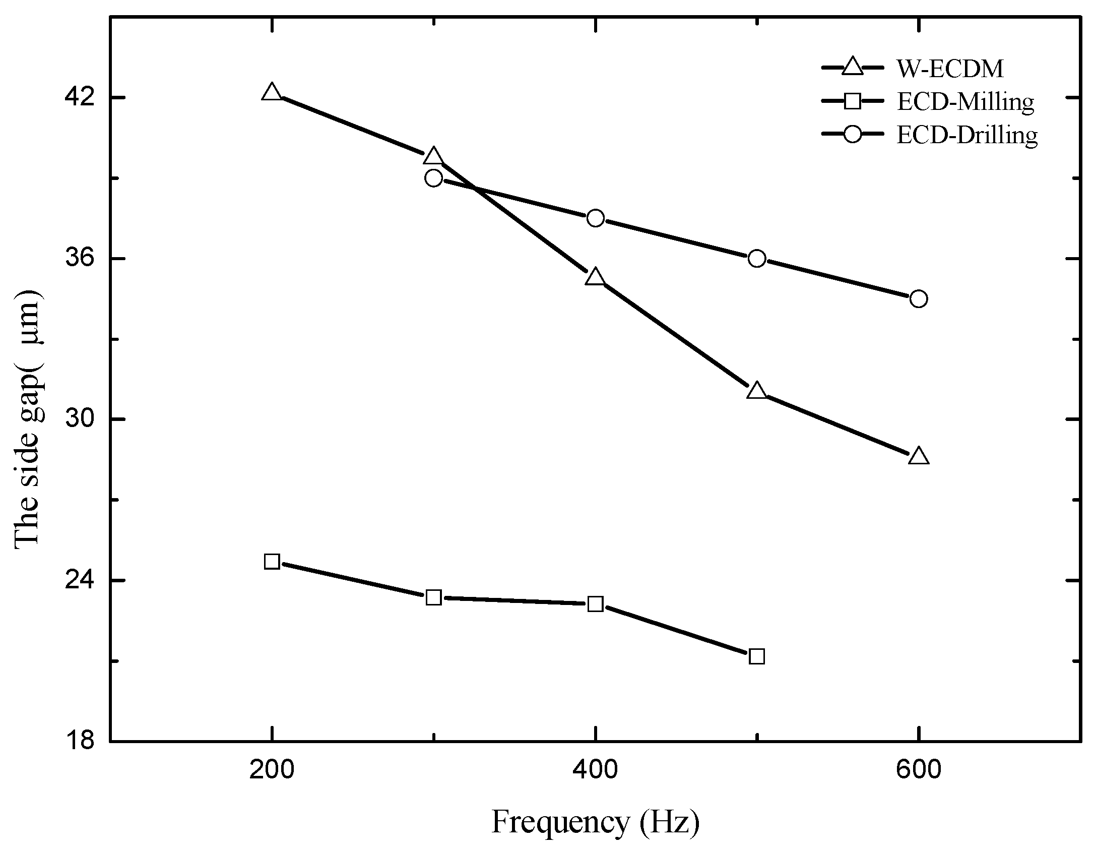
3.4. Effect of Frequency on Side Gap

The influence of frequency on the side gap is shown in Figure 7. In this set of experiments, the duty factor remained unchanged at 70% and frequency ranged from 200 Hz to 600 Hz. In electrochemical discharge drilling, electrochemical discharge milling, and wire ECDM the side gap decreased when the frequency increased, gradually. The number of discharge rose with higher frequency per unit time, but the pulse width was correspondingly reduced. Therefore, the discharge energy of a single discharge decreased, resulting in less material removal and smaller side gaps, eventually. The diameter of the hole in electrochemical discharge drilling, the slit width in electrochemical discharge milling and the wire ECDM decreased with the rise of frequency. The optimal frequency should be high but the higher frequency will reduce the material removal rate.

3.5. Effect of Feed Rate on Side Gap

Numerous experiments were conducted to research the effect of feed rate on the side gap. Different feed rates had different influences on the side gap, as displayed in Figure 8. Better machining location with s higher feed rate could be obtained with a lower side gap. The shorter discharge time with the higher feed rate in unit machining distance along the direction of feed, led to less material being removed. Therefore, the side gap was lower in the electrochemical discharge drilling, electrochemical discharge milling, and wire ECDM. However, the optimal feed rate was not higher. The rotary helical electrode collided with the workpiece when the feed rate rose to critical values.

4. Experimental Results

According to the above experiments and analysis, the effects of the parameters, including voltage, frequency, duty factor and feed rate, on the side gap were worked out in ECDM with rotary helical electrodes. The parameters, after optimization, were selected based on many experiments exploring fabricated micro holes, micro grooves, micro channels and complicated three-dimensional features with lower side gaps. There were some micro structures displayed.

4.1. Electrochemical Discharge Drilling of Array Micro Holes

According to the above discussion about the effect of the parameters on the side gap, the smaller side gaps needed a low voltage, low duty factor, high frequency, and high feed rate. However, considering material removal rate and machining stability, the experiments were carried out to select a set of optimized parameters for electrochemical discharge drilling. The optimized parameters were: pulse voltage—37 V, frequency—3000 Hz, duty factor—70%, feed rate—1 μm/s, spindle speed—3000 rpm, and electrolyte—3 mol/L KOH. High quality array micro holes were successfully fabricated with a lower diameter, as shown in Figure 9. Thickness of the glass was 300 μm. A minimum side gap of 27.2 μm could be obtained with electrochemical discharge drilling.

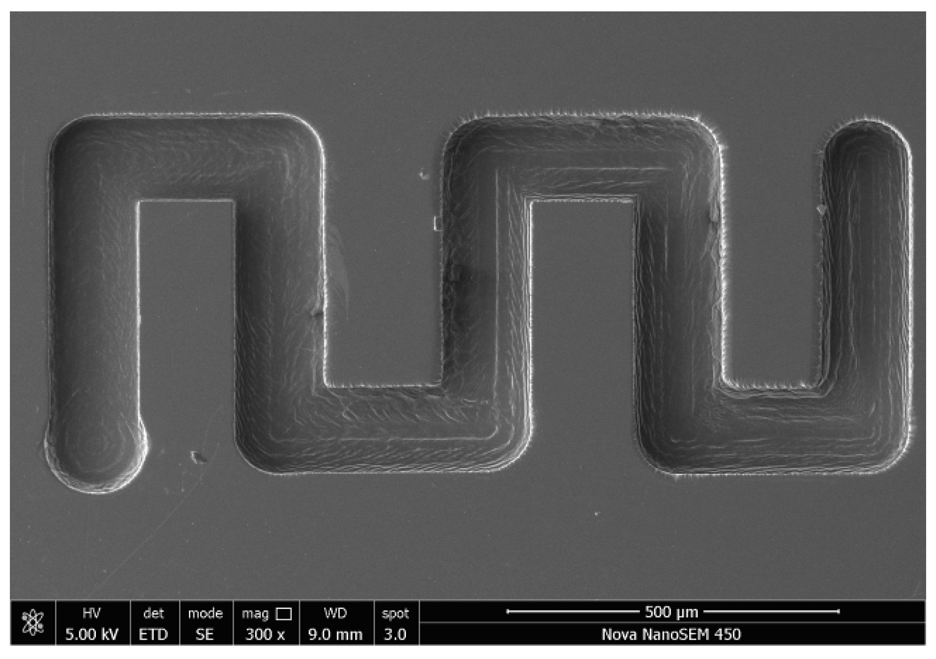
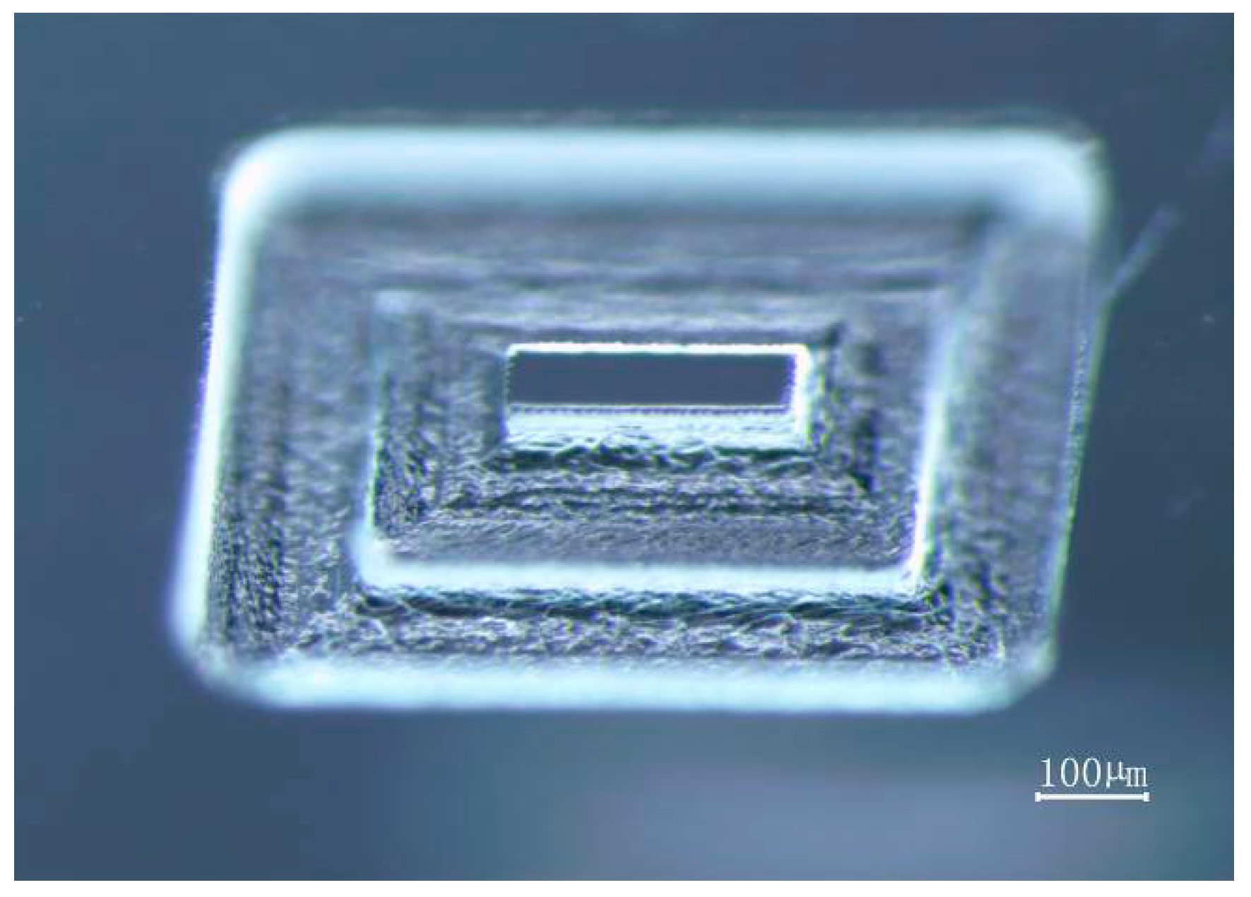
4.2. Electrochemical Discharge Milling of Micro Structures

Electrochemical discharge milling was capable of fabricating micro grooves, micro channels and micro three-dimensional structures. Some complex micro structures could be machined with a lower side gap by a set of optimized parameters. The optimized parameters were: pulse voltage—34 V, frequency—500 Hz, duty factor—50%, feed rate—2 μm/s, spindle speed—3000 rpm, and electrolyte—3 mol/L KOH. As shown in Figure 10, the micro groove array was milled on the glass. The mean width was 129.4 μm, the length was 750 μm and depth was about 130 μm. The smallest side gap reached 11.5 μm.
The micro channel machined on the glass by electrochemical discharge milling is displayed in Figure 11. The groove width was about 135.9 μm and the depth was about 150 μm. The abbreviation of the university name milled on the glass is shown in Figure 12. The three-dimensional step structure with vertical sidewalls and high shape accuracy is shown Figure 13. The three-dimensional convex structure of micro electrochemical discharge milling is shown in Figure 14, which is made of two layers of convex structures. The width of the upper convex plate was about 75 μm, the length was 260 μm and the height was about 70 μm.

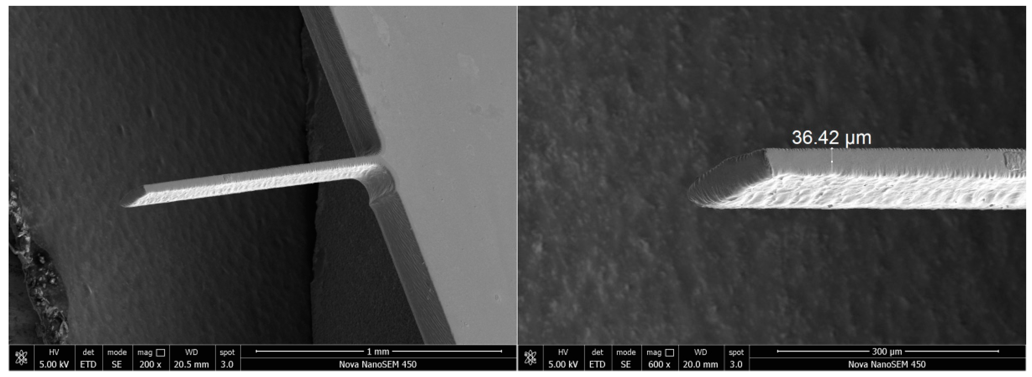
4.3. Wire Electrochemical Discharge of Micro Structures

Wire electrochemical discharge with rotary helical electrodes fabricated high aspect ratio structures. According to the above discussion and experiments, a set of optimized parameters was selected for machining the micro structures. Long narrow slits were fabricated on 300 μm thick glass, as shown in Figure 15. The smallest side gap reached 14.95 μm. The optimized parameters were: pulse voltage—34 V, frequency—600 Hz, duty factor—50%, and feed rate—1 μm/s. The closed micro structures were machined as displayed in Figure 16. To improve the refreshment of the electrolyte in the closed micro structures, larger processing parameters were used (40 V, 500 Hz, 50%, 1 μm/s).
The high aspect ratio structure was manufactured on 1060 μm thick glass with wire ECDM, using a rotary helical electrode. The slit width was about 175.4 μm and the side gap was about 35.2 μm, as shown in Figure 17 (40 V, 300 Hz, 60%, 1 μm/s). In addition, the micro cantilever beam was successfully fabricated on a 35 μm thick glass workpiece, as shown in Figure 18. The length of the micro cantilever beam was 1500 μm and the aspect ratio reached 42:1.

5. Conclusions

This research employed ECDM with a rotary helical electrode to fabricate ultra-clear glass. Using a rotary helical tool in electrochemical discharge drilling, electrochemical discharge milling, and wire ECDM, the effects of pulse voltage, frequency, duty factor, and feed rate on the side gap were investigated. The conclusions can be summarized as follows:
(1)
The mathematical model for the ECDM process was established to guide the machining of microstructures on ultra-clear glass.
(2)
The side gap increased with the increase in voltage and duty factor and was reduced with a higher frequency and feed rate in a certain range.
(3)
By employing optimized parameters in ECDM, micro holes, micro channels, micro slits and complicated three-dimensional features with ten several-micron side gaps were successfully fabricated on ultra-clear glass.

Author Contributions

Conceptualization, Y.L. and C.Z.; investigation, S.L. and Z.W.; methodology, C.G.; project administration, Y.L.; resources, Z.W.; writing—original draft, S.L.; and writing—review and editing, Y.L. and C.G.

Acknowledgments

The authors acknowledge financial support from the Shandong Provincial Natural Science Foundation (Nos. ZR2018MEE018, ZR2017BEE012), the China Postdoctoral Science Foundation (No. 2018M630772), the Young Scholars Program of Shandong University, Weihai (2015WHWLJH03), and the Shenzhen Science and Technology Project (JCYJ20170818103826176).

Conflicts of Interest

The authors declare no conflicts of interest.

References

  1. Allesu, K.; Ghosh, A.; Wuju, M.K. A preliminary qualitative approach of a proposed mechanism of material removal in electrical machining of glass. Eur. J. Mech. Eng. 1991, 36, 201–207. [Google Scholar]
  2. Zheng, Z.P.; Cheng, W.H.; Huang, F.Y.; Yan, B. 3D microstructuring of Pyrex glass using the electrochemical discharge machining process. J. Micromech. Microeng. 2007, 17, 960–966. [Google Scholar] [CrossRef]
  3. Díaz-Tena, E.; Gallastegui, E.; Hipperdinger, M.; Donati, E.R.; Ramírez, M. New advances in copper biomachining by iron-oxidizing bacteria. Corros. Sci. 2016, 112, 385–392. [Google Scholar] [CrossRef]
  4. Paredes-Sanchez, J.P.; Lopez-Ochoa, L.M.; Lopez-Gonzalez, L.M.; Las-Heras-Casas, J.; Xiberta-Bernat, J. Evolution and perspectives of the bioenergy applications in Spain. J. Clean. Prod. 2019, 213, 553–568. [Google Scholar] [CrossRef]
  5. Sanchez, J.A.; Plaza, S.; De Lacalle, L.N.; Lamikiz, A. Computer simulation of wire-EDM taper-cutting. Int. J. Comput. Integr. Manuf. 2006, 19, 727–735. [Google Scholar] [CrossRef]
  6. Nasim, S.; Mohammad, R.R.; Mansour, H. Experimental investigation of surfactant-mixed electrolyte into electro chemical discharge machining (ECDM) process. J. Mater. Process. Technol. 2017, 250, 190–202. [Google Scholar]
  7. Zhang, Z.Y.; Huang, L.; Jiang, Y.J.; Liu, G.; Nie, X.; Lu, H.Q.; Zhuang, H.W. A study to explore the properties of electrochemical discharge effect based on pulse power supply. Int. J. Adv. Manuf. Technol. 2016, 85, 2107–2114. [Google Scholar] [CrossRef]
  8. Sathisha, N.; Somashekhar, S.H.; Shivakumar, J. Prediction of material removal Rrate using regression analysis and artificial neural network of ECDM process. Int. J. Recent Adv. Mech. Eng. 2014, 3, 69–81. [Google Scholar]
  9. Jawalkar, C.S.; Sharma, A.P.; Kumar, P. Micromachining with ECDM: Research Potentials and Experimental Investigations. Channels 2012, 6, 340–345. [Google Scholar]
  10. Cao, X.D.; Kim, B.H.; Chu, C.N. Hybrid Micromachining of Glass Using ECDM and Micro Grinding. Int. J. Precis. Eng. Manuf. 2016, 14, 5–10. [Google Scholar] [CrossRef]
  11. Elhami, S.; Razfar, M.R. Effect of ultrasonic vibration on the single discharge of electrochemical discharge machining. Mater. Manuf. Process. 2017, 33, 444–451. [Google Scholar] [CrossRef]
  12. Elhami, S.; Razfar, M.R. Analytical and experimental study on the integration of ultrasonicallyvibrated tool into the micro electro-chemical discharge drilling. Precis. Eng. 2017, 47, 424–433. [Google Scholar] [CrossRef]
  13. Singh, T.; Dvivedi, A. Developments in electrochemical discharge machining: A review on electrochemical discharge machining, process variants and their hybrid methods. Int. J. Mach. Tools Manuf. 2016, 105. [Google Scholar] [CrossRef]
  14. Elhami, S.; Razfar, M.R. Study of the current signal and material removal during ultrasonic-assisted electro chemical discharge machining. Int. J. Adv. Manuf. Technol. 2017, 92, 1591–1599. [Google Scholar] [CrossRef]
  15. Han, M.S.; Min, B.K.; Lee, S.J. Modeling gas film formation in electrochemical discharge machining processes using a side-insulated electrode. J. Micromech. Microeng. 2008, 18, 19–26. [Google Scholar] [CrossRef]
  16. Furutani, K.; Maeda, H. Machining a glass rod with a lathe-type electro-chemical discharge machine. J. Micromech. Microeng. 2008, 18, 6–13. [Google Scholar] [CrossRef]
  17. Kun, L.W.; Hsin, M.L.; Kuan, H.C. Application of Electrochemical Discharge Machining to Micro-Machining of Quartz. Adv. Mater. Res. 2004, 939, 161–168. [Google Scholar]
  18. Tsuchiya, H.; Inoue, T.; Miyazaiki, M. Wire electro-chemical discharge machining of glasses and ceramics. Bull. Jpn. Soc. Precis. Eng. 1985, 19, 73–74. [Google Scholar]
  19. Jain, V.K.; Rao, P.S.; Choudhary, S.K.; Rajurkar, K.P. Experimental Investigations into Traveling Wire Electrochemical Spark Machining (TW-ECSM) of Composites. J. Eng. Ind. 1991, 113, 75–84. [Google Scholar] [CrossRef]
  20. Panda, M.C.; Yadava, V. Finite element prediction of material removal rate due to traveling wire electrochemical spark machining. Int. J. Adv. Manuf. Technol. 2009, 45, 506–520. [Google Scholar] [CrossRef]
  21. Kuo, K.Y.; Wu, K.L.; Yang, C.K.; Yan, B.H. Wire electrochemical discharge machining (WECDM) of quartz glass with titrated electrolyte flow. Int. J. Mach. Tools Manuf. 2013, 72, 50–57. [Google Scholar] [CrossRef]
  22. Wang, J.; Guo, Y.B.; Fu, C.; Jia, Z.X. Surface integrity of alumina machined by electrochemical discharge assisted diamond wire sawing. J. Manuf. Process. 2018, 31, 96–102. [Google Scholar] [CrossRef]
  23. Rattan, N.; Mulik, R.S. Improvement in material removal rate (MRR) using magnetic field in TW-ECSM process. Mater. Manuf. Process. 2017, 32, 101–107. [Google Scholar] [CrossRef]
  24. Huang, S.F.; Liu, Y.; Li, J.; Hu, H.X.; Sun, L.Y. Electrochemical Discharge Machining Micro-Hole in Stainless Steel with Tool Electrode High-Speed Rotating. Mater. Manuf. Process. 2014, 29, 634–637. [Google Scholar] [CrossRef]
  25. Han, M.S.; Min, B.K.; Lee, S.J. Geometric improvement of electrochemical discharge micro-drilling using an ultrasonic-vibrated electrolyte. J. Micromech. Microeng. 2009, 19, 65004. [Google Scholar] [CrossRef]
  26. Fang, X.L.; Zhang, P.F.; Zeng, Y.B.; Qu, N.S.; Zhu, D. Enhancement of performance of wire electrochemical micromachining using a rotary helical electrode. J. Mater. Process. Technol. 2016, 227, 129–137. [Google Scholar]
  27. Wang, M.Y.; Zhang, J.H.; Liu, Y.; Li, M.H. Investigation of Micro Electrochemical Discharge Machining Tool with High Efficiency. Recent Pat. Eng. 2016, 10, 146–153. [Google Scholar] [CrossRef]
  28. Jain, V.K.; Dixit, P.M.; Pandey, P.M. On the analysis of the electrochemical spark machining process. Int. J. Mach. Tools Manuf. 1999, 39, 165–186. [Google Scholar] [CrossRef]
Figure 1. A schematic view of electrochemical discharge machining (ECDM).
Processes 07 00195 g001
Figure 2. Experimental system of ECDM.
Processes 07 00195 g002
Figure 3. A schematic view of electrochemical discharge drilling.
Processes 07 00195 g003
Figure 4. Schematic view of electrochemical discharge milling.
Processes 07 00195 g004
Figure 5. Effect of pulse voltage on side gap.
Processes 07 00195 g005
Figure 6. Effect of duty factor on side gap.
Processes 07 00195 g006
Figure 7. Effect of frequency on side gap.
Processes 07 00195 g007
Figure 8. Effect of feed rate on side gap.
Processes 07 00195 g008
Figure 9. Array micro holes and partial magnification
Processes 07 00195 g009
Figure 10. Micro groove array on glass.
Processes 07 00195 g010
Figure 11. Complex micro channel on glass.
Processes 07 00195 g011
Figure 12. The abbreviation of the university name on glass.
Processes 07 00195 g012
Figure 13. Three-dimensional step structure.
Processes 07 00195 g013
Figure 14. Three-dimensional convex structure.
Processes 07 00195 g014
Figure 15. Long narrow slits on 300 μm thick glass workpiece.
Processes 07 00195 g015
Figure 16. Closed micro structure on 300 μm thick glass.
Processes 07 00195 g016
Figure 17. High aspect ratio structure on 1060 μm thick glass.
Processes 07 00195 g017
Figure 18. Micro cantilever beam on 35 μm thick glass workpiece.
Processes 07 00195 g018
Table 1. The details of experimental arrangements.
ItemECD-DrillingECD-MillingWire ECDM
Pulse voltage35–41 (V)34–40 (V)32–40 (V)
Frequency400–700 (Hz)200–500 (Hz)200–600 (Hz)
Duty factor60–90 (%)50–80 (%)50–90 (%)
Feed velocity0.5–2 (μm/s)0.5–2 (μm/s)0.5–2.5 (μm/s)
Spindle speed3000 (rpm)
Concentration3 M (KOH)

