Article

Experimental Research on Deep Silicon Removal in Spent SCR Catalysts

1
State Key Lab of Clean Energy Utilization, State Environmental Protection Engineering Center for Coal-Fired Air Pollution Control, Zhejiang University, Hangzhou 310027, China
2
Jiaxing Research Institute, Zhejiang University, Jiaxing 314031, China
3
Zhejiang University Energy Engineering Design and Research Institute Co., Ltd., Hangzhou 310027, China
*
Author to whom correspondence should be addressed.
Processes 2024, 12(2), 290; https://doi.org/10.3390/pr12020290
Submission received: 4 January 2024 / Revised: 23 January 2024 / Accepted: 26 January 2024 / Published: 29 January 2024
(This article belongs to the Special Issue Progress in Catalysis Technology in Clean Energy Utilization)

Abstract

:
In this research, hydrofluoric acid (HF) was used as a leaching agent to remove silicon impurities from titanium dioxide powder regenerated from a spent SCR catalyst. Further, the effects of HF concentration, liquid–solid ratio, leaching temperature, and leaching time on the leaching rate of regenerated titanium dioxide powder were investigated. The results revealed that the leaching rate of silicon in alkali-leached samples could reach 99.47% under the following conditions: 4% HF concentration, a leaching temperature of 50 °C, and a liquid–solid ratio of 5:1. When compared under identical experimental conditions, the silicon leaching rate in the alkali leached sample using HF surpassed that of the spent SCR catalyst. This suggests that high-temperature alkali leaching led to the degradation of the catalyst and the glass fiber within it, rendering this process more favorable for silicon leaching.

1. Introduction

Coal-fired power plants produce large amounts of nitrogen oxides (NOx), polluting the environment and endangering public health. Generally, thermal power plants use selective catalytic reduction (SCR) denitration technology to reduce air pollution [1]. V2O5/TiO2-based catalysts are recognized as the most advanced and commonly applied catalysts in SCR technology [2]. However, the SCR catalyst loses its activity during the denitration process due to sintering, wear, poisoning, and other factors. Typically, the service life of an SCR catalyst is usually only 2–3 years [3]. Many power plants use coal with high ash and high sulfur content, accelerating catalyst deactivation and shortening the service life of the catalyst [4]. Once the catalyst loses its regeneration value due to irreversible deactivation [5], it is discarded. The thermal power industry alone produces more than 200,000 cubic of catalyst waste every year [4]. Spent SCR catalysts contain harmful elements such as vanadium and arsenic. If disposed of improperly, the catalyst wastes will cause soil and water pollution, severely damaging the ecological environment [6,7].
Additionally, metals found in depleted SCR catalysts, like vanadium, tungsten, and titanium, hold immense value in terms of industrial application. It is a waste-to-landfill waste catalyst [8]. Thus, the resource utilization of spent SCR catalysts does not only solve the problem of waste pollution but also brings enormous economic benefits.
TiO2 is the primary component in the SCR denitration catalyst and accounts for 70–80% of the mass percentage of the spent catalyst [7]. Indeed, the titanium content is notably higher compared to the titanium concentrate typically utilized in the production of titanium dioxide. TiO2 is a transition metal oxide semiconductor material characterized by its low cost, non-toxicity, resistance to chemical erosion, and good light stability. It is widely used in carrier preparation, photocatalysis, sensors, etc. [9,10,11]. Therefore, spent SCR catalyst is a vital secondary resource with high economic recovery value. The typical procedure for TiO2 recovery from spent SCR catalysts begins by leaching vanadium and tungsten. Subsequently, the filter residue undergoes a process to eliminate silicon, aluminum, and other impurities, resulting in the acquisition of pure TiO2 products.
The titanium separation and recovery methods include the sodium roasting method and the strong alkali or strong acid leaching method [12,13]. Chen et al. [14] used sulfuric acid solution (20% mass fraction) to simultaneously leach V, W, Ti, and other metals from spent SCR catalyst and obtained titanium–tungsten carrier via hydrolysis and precipitation, which had minimal impurities and could be used to prepare new SCR catalyst. Cheng et al. [15] reported the use of oxalic acid and sodium hydroxide solution to leach the spent SCR catalyst. In the process, metals other than titanium were almost completely leached. Cheng et al. also reported that the acid-leaching process had no impact on the crystal structure of TiO2. In contrast, the high-temperature alkali leaching process converted a part of TiO2 into amorphous sodium titanate. Chen Yingmin et al. [16], Ma et al. [17], and Zhang et al. [18] recovered TiO2 from spent SCR catalysts via the process of sodium roasting-hot water leaching-sulfuric acid (or HCl) washing. Although TiO2 leaching and recovery rate can reach values > 90%, the separated TiO2 is in mixed crystal form (anatase and rutile). Song et al. [19] mixed Na2CO3 and NaCl-KCl with spent SCR catalysts for roasting and water leaching. The roasting temperature and the amount of sodium carbonate were reduced by introducing molten salt into the roasting system. Notably, the leaching residue TiO2-Na2Ti6O13 can be used as an adsorbent for heavy metal pollutants. Wu Wenfen et al. [4] used NaOH solution to leach W, followed by sulfuric acid or HCl to wash, activate, and then calcine to obtain anatase and rutile TiO2. Ma et al. [20] removed silicon and aluminum from the waste catalyst by microwave-assisted alkaline leaching, and then leached vanadium and tungsten through high-pressure alkaline leaching. Cao et al. [21] achieved complete leaching of vanadium and tungsten elements from a spent SCR catalyst by applying a mixed solution of hydrogen peroxide and ammonium bicarbonate. The residue was washed, dried, and ground to obtain anatase TiO2. The crystal phase of the obtained TiO2 did not change in the ingress and egress process and therefore it can be employed as a catalyst carrier. In summary, the published research on SCR catalyst resource utilization indicates the possibility of separation of valuable metals—titanium, vanadium, and tungsten—from spent SCR catalysts. Consequently, relatively pure vanadium and tungsten products could be extracted [22,23,24]. However, only a few studies have focused on the purification of titanium products. Further, the silicon impurity in the regenerated TiO2 powder was still high (>5%) after acid leaching [25], alkali leaching 18], and alkali roasting-leaching [19]. This reduced the purity of TiO2 products and limited their application scope. Therefore, it is necessary to remove silicon impurities in TiO2 to obtain high-purity products.
This research aims to improve the purity of TiO2 products recovered from spent catalysts. HF was employed for leaching silicon from spent catalysts, focusing on investigating the removal of silicon in spent catalysts under different experimental conditions to provide a feasible route to obtain high-purity TiO2 products cost-effectively.

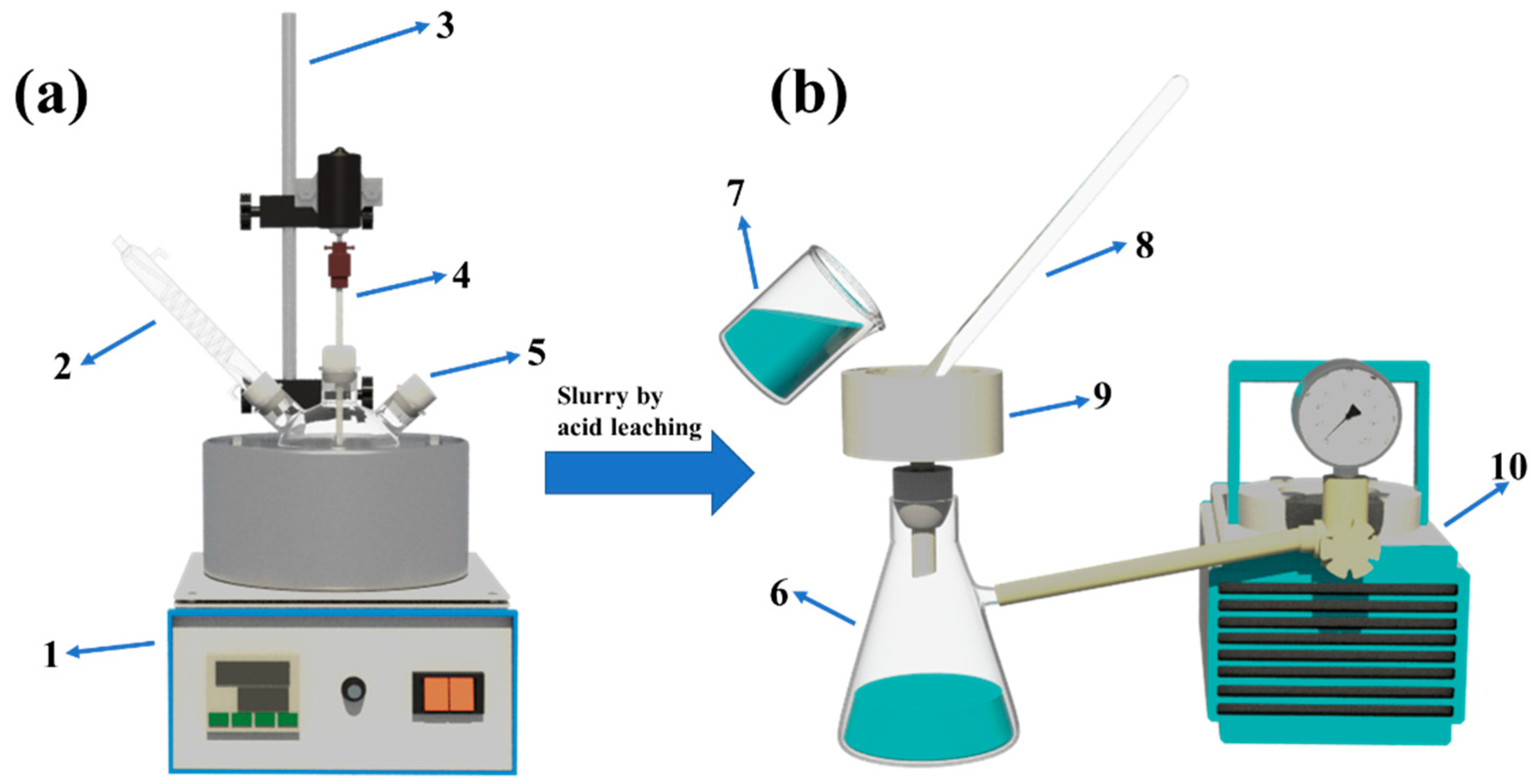
2. Experimental System and Method

2.1. Reagent, Material, and Instrument

Analytically pure concentrated HCl with a mass fraction of 36%, HF, and sodium hydroxide were used.
The spent SCR denitration catalyst selected was the spent honeycomb SCR catalyst procured from a company in Ningbo. The catalyst was dusted, dried, and ground before use. Based on the results of the XRF analysis, the SiO2, V2O5, Al2O3, and TiO2 content was 4.29%, 1.27%, 1.15%, and 86.1%, respectively. The catalyst was marked with the subscript s since Sis represented the leaching rate of silicon in the spent SCR catalysts that had not been treated with alkali or acid.
The samples utilized in this experiment were derived from spent catalysts subjected to alkali leaching followed by acid washing. The experimental conditions included leaching with 2 mol/L NaOH, a temperature of 180 °C, a liquid–solid ratio of 3:1, and a reaction time of 3 h, followed by filtration and drying for 3 h. The dried sample was pickled with 5% HCl at 70 °C, with the liquid–solid ratio of 3:1, and the pickling time of 3 h. It was then filtered and washed with deionized water to pH > 5. The cleaned solid sample was placed into a drying oven at 110 °C for 4 h and ground to 100~200 mesh for further use. The sample was called an alkali-leached acid-washed sample, marked with the subscript a, i.e., Sia represents the leaching rate of silicon in the leached sample. XRF analysis of the sample revealed that the SiO2 content in the sample was 3.38%, the V2O5 content was 0.309%, the Al2O3 content was 0.092%, and the TiO2 content was 92.9%.
The following instruments were obtained from the respective manufacturers/suppliers: ME104E electronic balance—Mettler-Toledo International Trading Co., Ltd., Zurich, Switzerland; DF-101S collector constant temperature heating magnetic stirrer—Yuhua Instrument Co., Ltd., Gongyi, China; Vacuum pump—Hangzhou David Scientific and Educational Instrument Co., Ltd., Hangzhou, China; Electric thermostatic temperature drying oven—Shanghai Jinghong Laboratory Instrument Co., Ltd., Shanghai, China.

2.2. Experimental Methods

The catalyst acid leaching silicon removal experiment was performed in a flask, in which a plastic flask was used for HF leaching (Figure 1). The catalyst sample was ground to 100~200 mesh. A certain amount of sample was weighed and added to the flask, followed by the addition of the acid solution based on the specified liquid–solid ratio, and reacted according to the set temperature and speed. A condenser tube was inserted at the top of the flask to condense the acid solution to prevent it from evaporating due to the higher temperature. After the reaction was completed, the heating was stopped, and the solution was processed by vacuum filtration and then washed with deionized water to obtain the leaching solution and wet residue. The wet residue was dried in a drying oven at 120 °C for 4 h and then ground to 100~200 mesh for later use.
The leaching rate of each element in the catalyst was calculated using Equation (1).
η i = C i × V C i × V + m i × 100 %
where Ci is the concentration of each element in the leaching solution, g/L;
mi is the mass of each element in the leaching residue, g;
V is the total volume of the leaching solution, L.

2.3. Characterization Methods

Inductively coupled plasma optical emission spectrometry (ICP-OES) was used for the qualitative and quantitative analysis of each element in the solution. This experiment selected optima 9000 ICP-OES from PE company (Pocasset, MA, USA) to qualitatively and quantitatively analyze the elements, like V, W, Si, Al, Na, Ca, and As, in the solution.
A surface analyzer (ASAP2460, Micromeritics Instrument, Norcross, GA, USA) was used to record N2 adsorption/desorption isotherms to determine the specific surface area, average pore size, and total pore volume of the sample.
The crystal structure of the sample was analyzed using the XRD diffractometer (X’Pert Pro, Panalytical, Almelo, The Netherlands). The experimental instrument was an X-ray diffractometer (Rigaku, D/max-2200, Tokyo, Japan) equipped with a Cu Kα light source (λ = 0.15405 nm, 40 mV, 200 mA). The scanning range was 10–90°, the scanning speed was 10°min−1, and the scanning step was equivalent to 0.02°.
The morphology and particle size of samples were analyzed using the Japanese Hitachi SU-8010 scanning electron microscope (SEM). The samples were evenly dispersed on the conductive adhesive and sprayed with gold before testing.
The X-ray fluorescence spectrometer (XRF) ZSX105e from Hitachi (Japan) was used to test the chemical element composition and content of the sample.

3. Results and Discussion

3.1. Investigating the Influence of Experimental Conditions on Silicon Leaching from Spent Catalysts

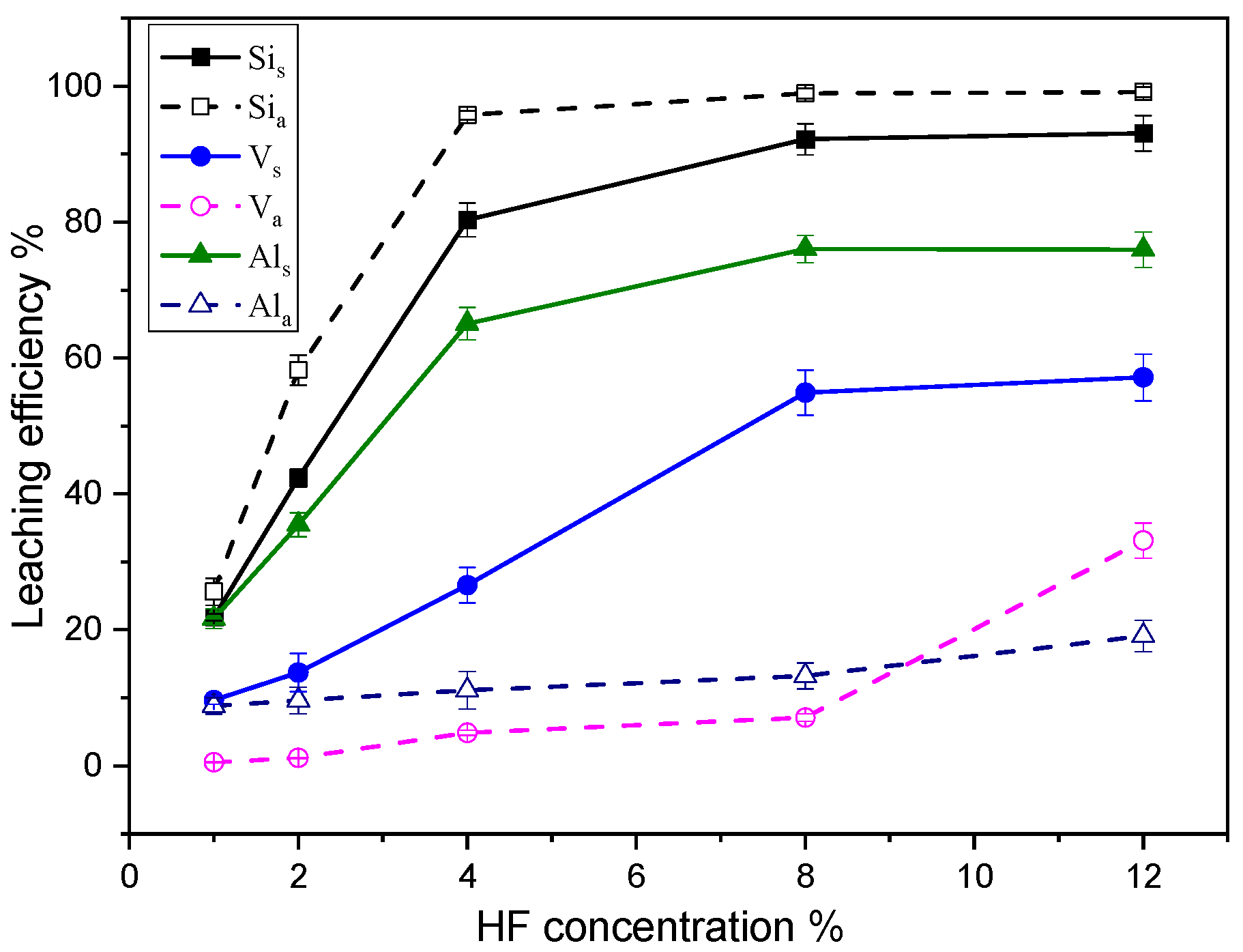
3.1.1. Effect of Leaching Agent Concentration

The concentration of leaching agent (hydrofluoric acid; HF) on the leaching rates of silicon, vanadium, and aluminum from spent SCR catalyst before and after alkali leaching is compared under the following reaction conditions: temperature—50 °C, time—120 min, and liquid–solid ratio—3:1 (See Figure 2). As shown in the figure, the leaching rate of each component in the spent catalyst increases with the increase in HF concentration. For alkali-leached samples, the silicon leaching rate is 25.63% when the HF concentration is 1%. The leaching rate increases rapidly with the increasing HF concentration; when the HF concentration increases to 4%, the leaching rate of silicon reaches 95.74%. The increase in HF concentration has little effect on the silicon leaching rate. The silicon leaching rate reached 99.13% with a 12% HF concentration, nearly achieving complete leaching. In alkali-leached samples, the HF has little effect on the leaching efficiency of vanadium and aluminum. When the concentration of HF was 12%, the leaching rates of vanadium and aluminum were recorded as 33.16% and 19.12%, respectively. This was attributed to the low content of aluminum and vanadium in the alkaline leaching sample. For the spent SCR catalysts without alkali leaching, HF was found to have a minor leaching effect on these three elements. When the HF concentration was 1%, the leaching rates of silicon, vanadium, and aluminum were 21.87%, 9.68%, and 21.67%, respectively.
Further, the leaching rates of silicon, vanadium, and aluminum were 92.2%, 54.93%, and 76.05%, respectively, when the HF concentration was increased to 8%. The continuous increase in HF concentration had minimal effect on the leaching rate of the catalyst. It was found that HF has a more significant impact on silicon leaching in alkali-leached samples, implying that the damage to the catalyst structure during the alkali-leaching process is more conducive to silicon leaching.

3.1.2. Influence of the Liquid–Solid Ratio

Figure 3 shows the effect of the liquid–solid ratio on the leaching rates of silicon, vanadium, and aluminum from different samples studied under a reaction temperature of 50 °C, a reaction time of 120 min, and an HF concentration of 2%, and 4%. The leaching rates of silicon, vanadium, and aluminum increase significantly with increasing the liquid–solid ratio since a high liquid–solid ratio is more conducive to the complete mixing of the leaching agent and sample. Consequently, this mixing amplifies the contact area for reactions and diminishes the diffusion resistance of soluble metals into the solution, thereby facilitating the leaching of metals.
For alkali-leached samples, when the concentration of HF is 2%, and the liquid–solid ratio is 10:1, and the silicon leaching rate reaches 99.46%. Additionally, increasing the liquid–solid ratio at this concentration has little effect on the leaching rate of vanadium and aluminum; the leaching rate being <10%. When the HF concentration is 4% and the liquid–solid ratio is 3:1, the leaching rate of silicon reaches 95.74%, indicating that a higher liquid–solid ratio increases the concentration gradient in the solution under the same total concentration of HF. Consequently, the mass transfer rate during leaching improves, which is more conducive to metal leaching.
The leaching efficiency of these three elements also increases with the increase in the liquid–solid ratio for spent SCR catalysts without acid and alkali treatment. But when the HF concentration is 4% and the liquid–solid ratio is 5:1, the leaching rates of silicon, vanadium, and aluminum are 88.77%, 44.08%, and 75.08%, respectively. Further increase in the liquid–solid ratio has little effect on the leaching of the catalyst. In contrast, the increase in the liquid–solid ratio increases the leaching agent dosage, which is not conducive to the subsequent processing of the leaching solution. Therefore, the liquid–solid ratio should not be higher than 5:1 in actual application.

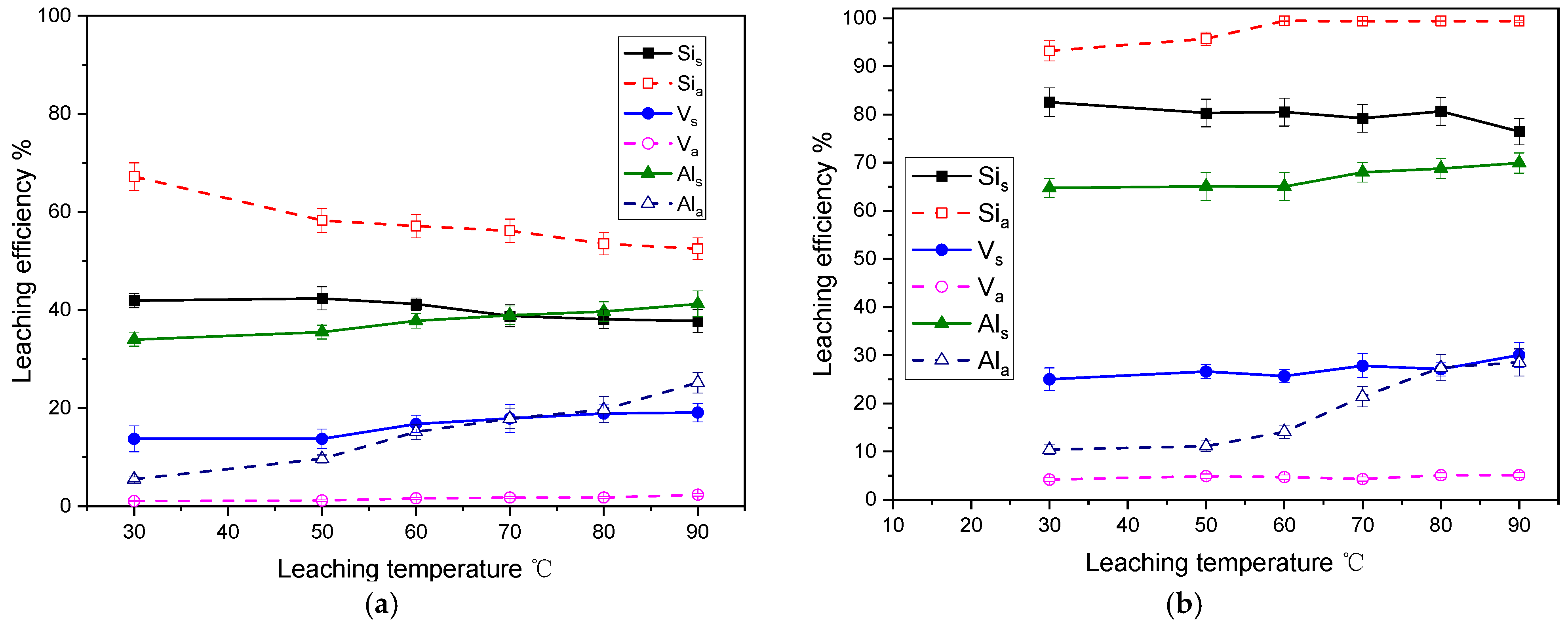
3.1.3. Effect of Leaching Temperature

The leaching rates of silicon, vanadium, and aluminum under different leaching temperatures are studied under the conditions of a liquid–solid ratio of 3:1, reaction time of 120 min, and HF concentration of 2% and 4% (See Figure 4). The results indicated that higher leaching temperatures inhibited silicon leaching. When the HF concentration was 2% and the leaching temperature was 30 °C, the leaching rates of silicon in the alkali leached sample and spent catalyst were 67.18% and 41.69%, respectively. When the temperature increased to 90 °C, the leaching rates reduced to 52.5% and 37.73%, respectively.
However, when the concentration of HF increased to 4%, increasing temperature promoted silicon leaching in the alkali-leached sample. The leaching rate of silicon at 30 °C and 60 °C was 93.22% and 99.46%. Thus, at 60 °C, there was almost complete leaching. Further increase in temperature had little effect on the silicon leaching. Elevating the leaching temperature can moderately enhance the leaching of vanadium and aluminum. However, the increased reaction temperature leads to increased energy consumption for heating. Consequently, the optimal leaching temperature was established as 60 °C, considering both energy input and return efficiency.

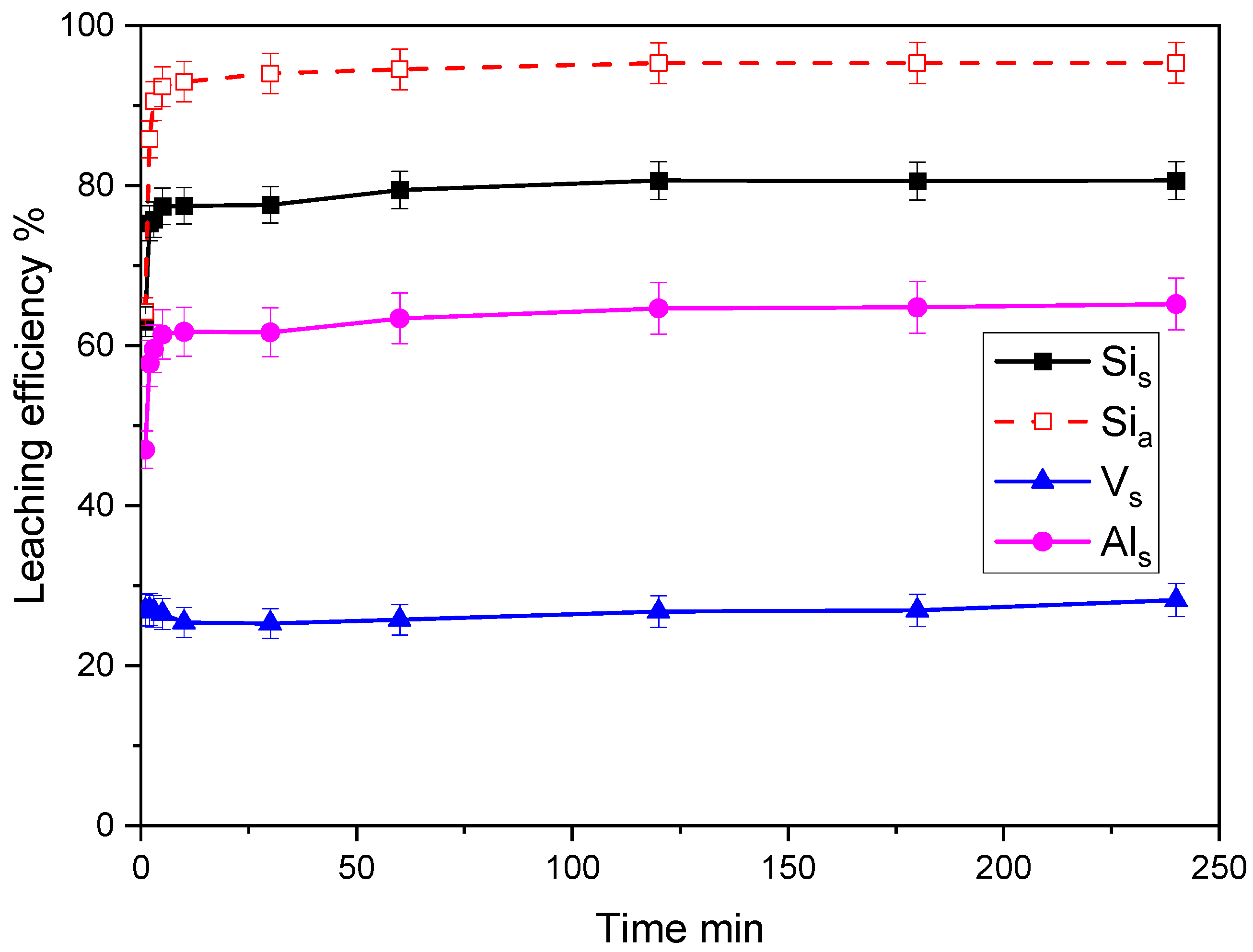
3.1.4. Effect of Leaching Time

The leaching rates of silicon, vanadium, and aluminum under different leaching times were studied under a liquid–solid ratio of 3:1, an HF concentration of 4%, and a leaching temperature of 50 °C (See Figure 5). The leachings of silicon, vanadium, and aluminum in the catalyst were rapid, with the leaching efficiency reaching equilibrium in 5 min. As the leaching time extends, the leaching efficiency experiences a gradual increase. Exploring the thermodynamic relationship of liquid–solid leaching reactions unveiled that the magnitude of chemical potential serves as a criterion to determine the direction and restriction of substance movement among components. When a substance exists in two phases, it shifts from the phase with higher chemical potential to the phase with lower chemical potential. Once the chemical potentials in the two phases become equal, the transfer halts, and the system attains equilibrium. During the leaching reaction, the chemical potential difference of substance in the liquid and solid phases decreases. At the point where the chemical potential reaches zero, the leaching reaction achieves equilibrium. During this phase, extending the alkali leaching time does not enhance the leaching rate. In industrial settings, optimizing productivity necessitates balancing high leaching efficiency with shorter leaching durations. The research outcomes recommend a 60 min leaching time as a better compromise meeting both requirements.

3.2. Influence of Acid Leaching on the Structure and Morphology of Catalysts

3.2.1. XRD Test Analysis

XRD was used to analyze the changes in the crystal phase structure of the spent catalyst, alkali leaching sample, spent catalyst-HF acid leaching sample, and alkali leaching sample-HF acid leaching sample. The X-ray diffractogram displayed in Figure 6 revealed that only the characteristic diffraction peaks of anatase TiO2 appeared in the XRD spectrum of the spent SCR denitration catalyst. No other diffraction peaks of other metal oxides were observed, indicating that other metal oxides were distributed on the TiO2 surface in an amorphous or highly dispersed state. In the alkali leaching sample, three small diffraction peaks at 13.9°, 24.2°, and 34.6° were observed in the XRD spectrum, in addition to the anatase TiO2 crystal phase. Comparing the three peaks with the powder diffraction file (PDF) in the standard database revealed that these peaks corresponded to the characteristic diffraction peaks of hydrated sodium aluminosilicate 1.08Na2O·Al2O3·1.68SiO2·1.8H2O (PDF 00-031-1271). The presence of Si and Al in the SCR catalyst was attributed to the fact that a part of the titanium silicon powder (TiO2-SiO2) and a small amount of glass fiber was used in the catalyst generation process—which was primarily present in the form of SiO2, Al2O3, and aluminosilicate and the reactions during the alkali leaching process were relatively complex. The XRD results revealed that apart from the soluble Na2SiO3 and Na2AlO2, a new sodium aluminosilicate structure was also formed during alkaline leaching, the reaction formulas are shown in (2)~(5). When HF was utilized for acid leaching, the sodium aluminosilicate structure disappeared, and only the characteristic diffraction peaks of anatase TiO2 were observed in the XRD spectrum, indicating that HF reacts with sodium aluminosilicate to leach silicon.
Al 2 O 3 + 2 NaOH ( aq ) + 3 H 2 O = 2 Al ( OH ) 4 ( aq ) - + 2 Na ( aq ) + .
SiO 2   + 2 NaOH   =   Na 2 SiO 3 +   H 2 O
Al 2 O 3 · 2 SiO 2 · 2 H 2 O ( s )   + 2 NaOH ( aq ) + 5 H 2 O   = 2 Al ( OH ) 4 ( aq ) - + 2 Si ( OH ) 4 ( aq )   + 2 Na ( aq ) +
xNaAlO 2 ( aq ) + yNa 2 SiO 3 ( aq ) + y + z H 2 O = Na x ( AlO 2 ) x ( SiO 2 ) y · zH 2 O + 2 yNaOH ( aq )

3.2.2. Specific Surface Area Analysis

Table 1 and Table 2 illustrate the effects of HF concentration on the surface structural properties of alkali-leaching samples and spent catalysts, respectively. The findings demonstrated that, in the alkali leaching sample, employing HF for leaching initially led to a decrease in the specific surface area, followed by an increase as the HF concentration rose. When the HF concentration increased from 0 to 2%, the specific surface area dropped from 81.98 m2/g to 74.01 m2/g, and the average pore size increased from 12.7 nm to 13.1 nm. As the HF concentration increased, the specific surface area of the alkali leaching sample increased again, while the average pore size decreased. When the HF concentration reached 12%, the specific surface area increased to 78.97 m2/g, whereas the average pore size was 12.2 nm. In contrast to the alkali leaching sample lacking HF treatment, both the specific surface area and average pore size were reduced. This alteration might be attributed to the addition of hydrofluoric acid, causing structural disruption in the aluminosilicate. Consequently, some pores collapsed, and others were obstructed, leading to a decline in the catalyst’s specific surface area and an increase in the average pore size. When the HF concentration is further increased, the leaching rates of silicon and aluminum increase and some small pores recover, which, in turn, increases the specific surface area. However, the average pore size decreases.
For the spent SCR catalyst, the specific surface area and pore volume of the catalyst decrease upon leaching with 1% HF. This decrease might also be caused by the collapse of some pores. With increasing HF concentration, the specific surface area and pore volume of the catalyst increase. When the HF concentration is 12%, the specific surface area and pore volume increase to 65.34 m2/g and 0.358 cm3/g, respectively, thereby implying that during the leaching process, the destruction of aluminosilicate structure and vanadium leaching may restore some of the original pores, while generating additional pores, which increases the catalyst’s specific surface area and pore volume.

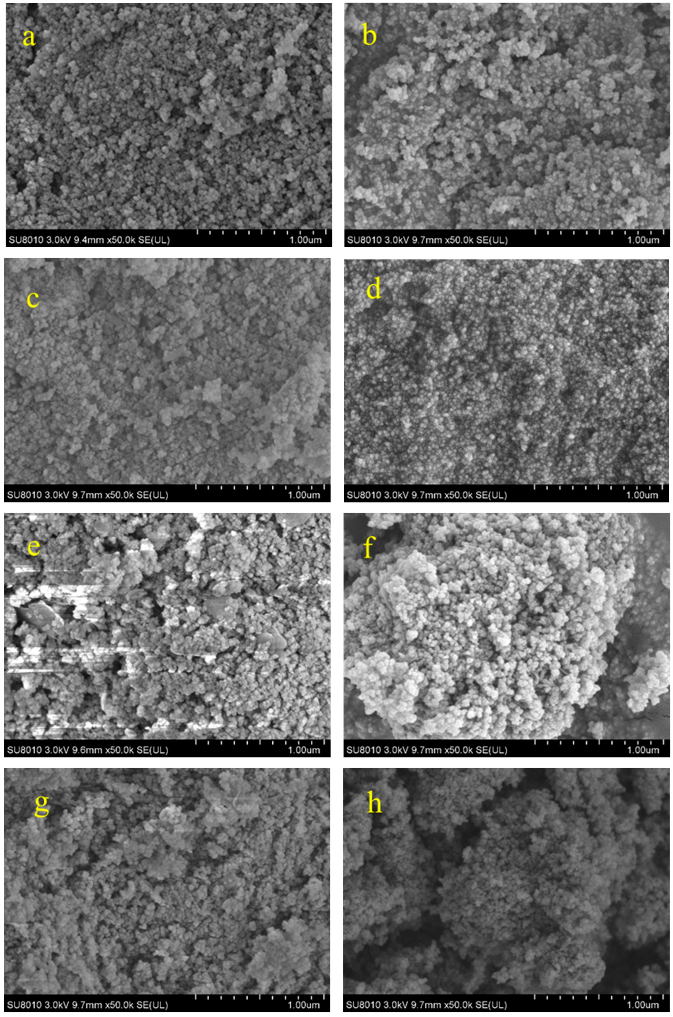
3.2.3. Morphology Analysis

Figure 7 shows the effect of HF concentration on catalyst morphology. The SEM image showed that for the alkali leaching sample, when the HF concentration was 1%, there were minor agglomerations on the surface of the sample, which may be attributed to the blocking of pores due to the destruction of the aluminosilicate structure. As the concentration of HF continued to increase, the particle size of the alkali leaching sample became significantly smaller, and finer primary particles appeared, which were probably part of the catalyst structure destroyed by HF, resulting in fine particles and smaller pores and reducing the average pore size, which was consistent with the results of the specific surface area. For the spent SCR catalysts that had not been treated with acid and alkali, post-HF leaching, the dense structure of the catalyst surface became fluffy, and the particle size reduced with an increase in HF concentration, which was consistent with the surface structural data presented in Table 2. This change can primarily be attributed to the leaching of aluminosilicate.
Based on the above experimental results, the optimal experimental conditions for alkali-leached samples were adjusted as follows: HF concentration of 4%, a liquid–solid ratio equal to 5:1, and a temperature of 50 °C. The obtained solution was filtered and washed until the pH > 5, followed by placing it in a drying box to dry at 120 °C for 4 h, and then ground to obtain a powder. The obtained sample was analyzed via X-ray fluorescence spectrum as shown in Table 3. The silicon was efficiently eliminated from the sample, with a residual content of merely 0.0819%. Additionally, the levels of other impurities in the catalyst were relatively low, resulting in a TiO2 purity of 97.5%. This sample holds potential as a raw material for fabricating new catalysts, thereby enabling the resource recycling of TiO2 from spent SCR catalysts.

4. Conclusions

This research utilized HF leaching to treat both the alkali-leached catalyst and the spent SCR catalyst sample to eliminate silicon from the catalyst and enhance the purity of TiO2. The influence of acid leaching conditions on catalyst leaching was investigated, and the variations in the physical structure and microscopic morphology of the catalyst were analyzed. The main conclusions from the research are as follows:
(1)
HF can react with silicon in the catalyst, destroying the structure of aluminosilicate in the catalyst, thereby facilitating silicon and aluminum leaching. Increasing HF concentration and liquid–solid ratio improves the leaching efficiency of silicon, vanadium, and aluminum in the sample by acid leaching. The increase in leaching temperature also inhibits the leaching of silicon in the sample while promoting the leaching of vanadium and aluminum. When the HF concentration is 4%, the liquid–solid ratio is 5:1, and the temperature is 50 °C, the leaching rate of silicon in an alkali-leached sample reaches 99.47%;
(2)
Under identical experimental conditions, the silicon leaching rate in the alkali-leached sample with HF was higher compared to the spent SCR catalyst. This suggests that high-temperature alkali leaching damages the catalyst and the glass fiber within it, thereby favoring silicon leaching;
(3)
For alkali-leached samples, HF treatment reduces the catalyst’s specific surface area to a certain extent. The particle and average pore size of the catalyst also decreases. In the spent SCR catalyst, the damage to the aluminosilicate structure and the leaching of vanadium restores some pores in the catalyst and forms some new pores, thereby increasing the specific surface area and the pore volume of the catalyst.

Author Contributions

Conceptualization, S.S.; Formal analysis, Z.H. and D.W.; Investigation, L.W. and S.S.; Data curation, H.S.; Writing—review & editing, Y.Z.; Supervision, S.L.; Project administration, W.W. and X.G. All authors have read and agreed to the published version of the manuscript.

Funding

This work was supported by the National Natural Science Foundation of China (No. 42341208, 51836006) and the Major Consulting and Research Project of Zhejiang Research Institute of China Engineering Science and Technology Development Strategy (2023ZL0003).

Data Availability Statement

The data supporting the findings of this study are available within the article.

Conflicts of Interest

Authors Weihong Wu, You Zhang, Sihui Song were employed by Zhejiang University Energy Engineering Design and Research Institute Co., Ltd. The remaining authors declare that the research was conducted in the absence of any commercial or financial relationships that could be construed as a potential conflict of interest.

References

  1. Tan, L.; Guo, Y.; Liu, Z.; Feng, P.; Li, Z. An investigation on the catalytic characteristic of NOx reduction in SCR systems. J. Taiwan Inst. Chem. Eng. 2019, 99, 53–59. [Google Scholar] [CrossRef]
  2. Kumar, M.S.; Alphin, M.S.; Manigandan, S.; Vignesh, S.; Vigneshwaran, S.; Subash, T. A review of comparison between the traditional catalyst and zeolite catalyst for ammonia-selective catalytic reduction of NO x. Fuel 2023, 344, 128125. [Google Scholar] [CrossRef]
  3. Zhang, T.; Chen, X.; Sun, C.; Yuan, D. Research progress on recovery and reuse of valuable metals from spent vanadium-titanium SCR catalysts. Mod. Chem. Ind. 2021, 27, 67–72, 77. [Google Scholar]
  4. Wu, W.F.; Li, H.Q.; Meng, Z.H.; Wang, C.Y.; Wang, X.R.; Zhao, C. Recovery of TiO2 from spent SCR denitration catalyst by alkali hydrothermal method. Chin. J. Process Eng. 2019, 19 (Suppl. S1), 72–80. [Google Scholar]
  5. Ferella, F. A review on management and recycling of spent selective catalytic reduction catalysts. J. Clean. Prod. 2020, 246, 118990. [Google Scholar] [CrossRef]
  6. Liu, Z.; Lin, D.; He, F.; Cao, Z.; Wang, B. Study of Leaching Mechanism and Kinetics of Vanadium and Tungsten on the Process of Recovery Spent SCR Catalyst by Sodium Roasted. Mater. Rep. 2021, 35, 429–433. [Google Scholar]
  7. China Environmental Protection Industry Association Desulfurization and Denitration Committee. China Development Report on Desulfurization and Denitration Industries in 2014; China Environmental Protection Industry: Beijing, China, 2015; Volume 12, pp. 4–23. [Google Scholar]
  8. Wu, Y.W.; Zhou, X.Y.; Hu, Z.; Cai, Q.; Lu, Q. A comprehensive review of the heavy metal issues regarding commercial vanadium-titanium-based SCR catalyst. Sci. Total Environ. 2023, 857, 159712. [Google Scholar] [CrossRef] [PubMed]
  9. Chen, Y.; Soler, L.; Cazorla, C.; Oliveras, J.; Bastús, N.G.; Puntes, V.F.; Llorca, J. Facet-engineered TiO2 drives photocatalytic activity and stability of supported noble metal clusters during H2 evolution. Nat. Commun. 2023, 14, 6165. [Google Scholar] [CrossRef]
  10. Chen, J.; Xiong, S.; Liu, H.; Shi, J.; Mi, J.; Liu, H.; Gong, Z.; Oliviero, L.; Maugé, F.; Li, J. Reverse oxygen spillover triggered by CO adsorption on Sn-doped Pt/TiO2 for low-temperature CO oxidation. Nat. Commun. 2023, 14, 3477. [Google Scholar] [CrossRef]
  11. Shaikh, S.F.; Ghule, B.G.; Nakate, U.T.; Shinde, P.V.; Ekar, S.U.; O’Dwyer, C.; Kim, K.H.; Mane, R.S. Low-Temperature Ionic Layer Adsorption and Reaction Grown Anatase TiO2 Nanocrystalline Films for Efficient Perovskite Solar Cell and Gas Sensor Applications. Sci. Rep. 2018, 8, 11016. [Google Scholar] [CrossRef] [PubMed]
  12. Tang, H.; Lu, Q.; Yang, J.; Li, H.; Li, W.; Yang, Y. Research on recycling and characterization analysis of the waste SCR catalyst. J. Fuel Chem. Technol. 2018, 46, 233–242. [Google Scholar]
  13. Zhang, Q.; Wu, Y.; Yuan, H. Recycling strategies of spent V2O5-WO3/TiO2 catalyst: A review. Resour. Conserv. Recycl. 2020, 161, 104983. [Google Scholar] [CrossRef]
  14. Zhao, C.; Wang, C.; Wang, X.; Li, H.; Chen, Y.; Wu, W. Recovery of tungsten and titanium from spent SCR catalyst by sulfuric acid leaching process. Waste Manag. 2023, 155, 338–347. [Google Scholar] [CrossRef] [PubMed]
  15. Cheng, K.; Yu, Y.; Mei, B.; Li, Y.; Xu, L. Efficient Recovery of V, W, and Regeneration of TiO2 Photocatalysts from Waste-SCR Catalysts. Sustainability 2022, 14, 10284. [Google Scholar] [CrossRef]
  16. Chen, Y.; Xie, Z.; Wang, C. Study on the TiO2 Recovery from SCR Catalyst Waste in Coal-Fired Power Plants. Electr. Power 2016, 49, 151–152. [Google Scholar]
  17. Ma, B.; Qiu, Z.; Yang, J.; Qin, C.; Fan, J.; Wei, A.; Li, Y. Recovery of nano-TiO2 from spent SCR catalyst by sulfuric acid dissolution and direct precipitation. Waste Biomass Valorization 2019, 10, 3037–3044. [Google Scholar] [CrossRef]
  18. Zhang, Q.J.; Wu, Y.F.; Zuo, T.Y. Green recovery of titanium and effective regeneration of TiO2 photocatalysts from spent selective catalytic reduction catalysts. ACS Sustain. Chem. Eng. 2018, 6, 3091–3101. [Google Scholar] [CrossRef]
  19. Song, C.; Zhou, D.; Yang, L.; Zhou, J.; Liu, C.; Chen, Z.-G. Recovery TiO2 and sodium titanate nanowires as Cd(II) adsorbent from waste V2O5-WO3/TiO2 selective catalytic reduction catalysts by Na2CO3-NaCl-KCl molten salt roasting method. J. Taiwan Inst. Chem. Eng. 2018, 88, 226–233. [Google Scholar] [CrossRef]
  20. Ma, L.W.; Xi, X.L.; Chen, J.P.; Guo, F.; Yang, Z.J.; Nie, Z.R. Comprehensive recovery of W, V, and Ti from spent selective reduction catalysts. Rare Met. 2023, 42, 3518–3531. [Google Scholar] [CrossRef]
  21. Cao, Y.; Yuan, J.; Du, H.; Dreisinger, D.; Li, M. A clean and efficient approach for recovery of vanadium and tungsten from spent SCR catalyst. Miner. Eng. 2021, 165, 106–857. [Google Scholar] [CrossRef]
  22. Tang, D.; Song, H.; Liu, D.; Wu, W.; Zheng, C.; Gao, X. Study on leaching kinetics of extracting vanadium and tungsten by sodium hydroxide from spent SCR catalyst. Chin. J. Environ. Eng. 2017, 11, 1093–1100. [Google Scholar]
  23. Liu, D.; Song, H.; Wu, W.; Zheng, C.; Qiu, K.; Gao, X. Influence Law of Solution pH on Separation of Vanadium and Tungsten by Ion Exchange Adsorption. Rare Met. Cem. Carbides 2018, 46, 7–12. [Google Scholar]
  24. Lin, Z.; Song, H.; Wu, W.; Liu, S.; Zheng, C.; Gao, X. Extraction of vanadium from alkaline leached solution of spent SCR catalyst using quaternary ammonium salt N263. Environ. Prot. Chem. Ind. 2021, 41, 571–575. [Google Scholar]
  25. Zhang, Q.; Wu, Y.; Li, L.; Zuo, T. A sustainable approach for spent V2O5-WO3/TiO2 catalysts management: Selective recovery of heavy metal vanadium and production of value-added WO3-TiO2 photocatalysts. ACS Sustain. Chem. Eng. 2018, 6, 12502–12510. [Google Scholar] [CrossRef]
Figure 1. Sketch of acid leaching system: (1) Thermostatic water bath. (2) Condensation tube. (3) Bracket. (4) Stirrer. (5) Three-necked flask. (6) Suction flask. (7) Acid leaching solution. (8) Glass rod. (9) Core Buchner funnel. (10) Vacuum pump. (a) acid leaching system. (b) filtration system.
Processes 12 00290 g001
Figure 2. Effect of HF concentration on Si, V, and Al leaching efficiency.
Processes 12 00290 g002
Figure 3. Effect of liquid–solid ratio on leaching efficiency. (a) HF concentration is 2%; (b) HF concentration is 4%.
Processes 12 00290 g003
Figure 4. Effect of leaching temperature on leaching efficiency. (a) HF concentration is 2%; (b) HF concentration is 4%.
Processes 12 00290 g004
Figure 5. Effect of leaching time on the leaching efficiency.
Processes 12 00290 g005
Figure 6. XRD spectrum of the catalyst. (a) Spent SCR catalyst. (b) Alkali leaching sample. (c) Spent catalyst-HF acid leaching sample. (d) Alkali leaching sample-HF acid leaching sample.
Processes 12 00290 g006
Figure 7. SEM images of different HF concentrations. Catalyst after alkali leaching treatment: (a) 0% HF, (b) 1% HF, (c) 4% HF, (d) 12% HF. Spent SCR catalyst: (e) 0% HF, (f) 1% HF, (g) 4% HF, (h) 12% HF.
Processes 12 00290 g007
Table 1. Effect of HF concentration on the surface structural characteristics of the alkali leaching sample.
SampleHF Concentration/%Specific Surface Area/(m2·g−1)Total Pole Volume/(cm3·g−1)Average Pore Size/(nm)
1081.980.27912.7
2177.920.26912.9
3274.010.26613.1
4476.930.26412.6
5878.240.26912.5
61278.970.26912.2
Table 2. Effect of HF concentration on surface structural characteristics of spent catalyst.
SampleHF Concentration/%Specific Surface Area/(m2·g−1)Total Pore Volume/(cm3·g−1)Average Pore Size/(nm)
Spent catalyst047.880.23618.5
1146.920.23418.1
2258.730.28518.04
3461.510.28317.4
4862.170.29617.1
51265.340.35819.3
Table 3. Analysis of components of acid-leached sample.
ElementV2O5TiO2WO3SiO2Al2O3CaO
Content (%)0.1597.51.840.08190.0140.009
ElementMgOFe2O3Na2OK2OAs2O5
Content (%)0.00150.139not detectednot detected0.036
Disclaimer/Publisher’s Note: The statements, opinions and data contained in all publications are solely those of the individual author(s) and contributor(s) and not of MDPI and/or the editor(s). MDPI and/or the editor(s) disclaim responsibility for any injury to people or property resulting from any ideas, methods, instructions or products referred to in the content.

