Article

Simulation Analysis of the Influence of Amplitude on Deformation and Fracture Characteristics of Hard Rock under Ultrasonic Vibration Load

School of Mines, Jiangsu Engineering Laboratory of Mine Earthquake Monitoring and Prevention, China University of Mining and Technology, Xuzhou 221116, China
*
Author to whom correspondence should be addressed.
Processes 2024, 12(1), 74; https://doi.org/10.3390/pr12010074
Submission received: 13 December 2023 / Revised: 25 December 2023 / Accepted: 26 December 2023 / Published: 28 December 2023
(This article belongs to the Special Issue Geochemical Processes and Environmental Geochemistry of Modern Mining)

Abstract

:
The utilization of auxiliary tools employing ultrasonic high-frequency vibration to enhance rock breaking efficiency holds significant potential for application in underground hard rock excavation engineering. To investigate the failure mechanism of rocks under high frequency ultrasonic vibration load, this study employs particle flow software PFC2D for numerical simulation. By incorporating boundary conditions from actual ultrasonic vibration rock breaking experiments and utilizing a parallel bond model to construct the rock, we analyze the deformation, damage, fracture, and energy evolution process of hard rocks subjected to vibrational loads. The results demonstrate that the maximum displacement in hard rocks increases nearly linearly with vibrations until reaching 5.0199 × 10⁻³ m, after which it plateaus. Additionally, macroscopic fissures formed during rock failure exhibit an X-shaped pattern. Furthermore, based on our model, we examine the impact of amplitude variation on hard rocks with an equal number of cycles (5,000,000 cycles). Under ultrasonic vibration loads, amplitude influences the total input energy within the rock system. While increasing amplitude does not alter maximum deformation in rocks, it enhances fragmentation degree, fracture degree and energy dissipation coefficient—thereby improving rock breaking efficiency.

1. Introduction

Energy serves as a pivotal foundation for societal advancement. As shallow strata resources gradually deplete, the pursuit of resource exploration and development is progressively shifting towards deeper, more resilient, and intricate strata. In China, for instance, coal mining operations have reached depths exceeding 500 m. Currently employed rock fragmentation techniques in coal mining encompass mechanical methods and drilling with blasting approaches. However, the conventional mechanical method is increasingly inadequate for tackling hard strata while the drilling and blasting method exhibits certain drawbacks such as compromised safety measures and limited automation feasibility. Consequently, there arises an imperative need to cultivate novel rock fragmentation technologies that are both efficient and secure.
Compared to the conventional underground hard rock crushing method, high-frequency vibration rock breaking technology offers several advantages: Firstly, it can be seamlessly integrated with mechanical equipment to facilitate automation. Secondly, the impact of high-frequency vibration significantly reduces the time required for rock fatigue damage, thereby alleviating the fragmentation difficulty associated with hard rocks. Thirdly, within a specific range, the vibrational load induces resonance in hard rocks and leads to severe internal deformation during this resonant state, further reducing the challenges encountered in crushing hard rocks. The novel application of ultrasonic vibration rock technology, characterized by its low power consumption and efficient rock fragmentation, is introduced for the first time in space sampling [1,2,3]. The first ultrasonic rotary impact drilling test platform was constructed by Wiercigroch, which, in combination with testing and theoretical analysis, demonstrated the effective enhancement of rock breaking efficiency through the introduction of ultrasonic vibration into traditional drilling methods [4]. These investigations offer novel insights for the efficient fragmentation of deep hard rock.
In recent years, extensive research has been conducted on the mechanism of rock deformation damage and fracture under cyclic loading. Wang performed uniaxial cyclic compression tests at different frequencies on coal samples and observed that the elastic modulus of coal exhibited an initial sharp increase followed by a subsequent sharp decrease with increasing number of cyclic loading cycles [5]. Liu investigated the mechanical and failure characteristics of coal subjected to cyclic load under high stress and discovered a positive correlation between compressive strength of specimens and cyclic loading rate, as well as identified tensile failure as the microfailure mechanism during cyclic loading [6]. Vaneghi determined that higher load amplitudes resulted in greater degrees of strength degradation in hard rock, while also observing more localized fractures compared to static loading conditions [7]. Erarslan conducted a study on the tensile strength of limestone under cyclic loading and observed a 30% decrease in rock’s tensile strength under sinusoidal loading. Furthermore, intergranular fracture and transgranular fracture were identified within the rock [8]. Liu investigated the deformation and failure characteristics of rocks with different lithologies subjected to cyclic loading, revealing that sandstone exhibited superior energy storage capacity and experienced the highest degree of damage [9]. Fan, utilizing real-time CT scanning technology, analyzed the mesoscopic damage evolution features of granite under cyclic load. It was discovered that rock porosity remained unaffected when subjected to cyclic stress lower than 46.04% of its uniaxial compressive strength [10]. Erarslan examined the response characteristics of rock fracture resistance to cyclic load, observing a maximum reduction in static fracture toughness (KIC) by 27% under sinusoidal cyclic load [11].
The cyclic load frequencies investigated in the aforementioned studies are all below 100 Hz, and the mechanical properties of rocks under high-frequency vibration differ significantly from those under low-frequency vibration [12]. Currently, there is a scarcity of relevant research on rock fragmentation through high-frequency vibration. Some scholars have independently developed a high-frequency vibration testing platform to investigate the deformation and failure characteristics of rocks subjected to ultrasonic vibrations using experimental and numerical simulation approaches. Li utilized the finite element method to simulate the rock intrusion process of a cylindrical indenter under high-frequency vibration [13]. The comprehensive analysis of deformation displacement field and stress field of rocks was conducted by considering various parameters such as amplitude, frequency, load surface position, etc. Yin investigated the mechanical properties of rocks under static loads through mechanical experiments and discovered that optimal static load could maximize the damage degree of rocks [14]. Zhou monitored strain in granite samples subjected to ultrasonic vibration and categorized rock deformation into elastic deformation, plastic deformation, and damage stages; it was also pointed out that when the vibration frequency approached natural frequency of rock, maximum displacement amplitude on rock surface was achieved [15]. In our previous studies [16,17], we performed uniaxial compressive tests and nuclear magnetic resonance tests which revealed that ultrasonic vibrations facilitated initiation and expansion of micro-pores in rocks while increasing static load expanded range for rock rupture.
Currently, the majority of studies primarily focus on investigating the macroscopic mechanical properties of rocks under ultrasonic vibration excitation. However, a significant challenge arises due to the inherent heterogeneity of rock materials, resulting in substantial deviations in test results even when sample size matches the vibration parameters of the testing system. Moreover, existing damage measurement methods like acoustic emission fail to provide real-time monitoring of crack growth throughout the entire excitation process. Consequently, there is a scarcity of research examining rock damage and fracture processes during ultrasonic vibration from an energy perspective. Building upon previous experimental studies, this paper employs PFC2D particle flow program to construct numerical simulations for sandstone and meticulously analyzes the evolution patterns of rock displacement field, force chain field, fracture field as well as energy dissipation characteristics under ultrasonic vibration load. The aim is to elucidate how amplitude influences rock damage and failure mechanisms

2. Numerical Simulation of Rock Breaking by Ultrasonic Vibration

2.1. Establishment of the Particle Flow Model

The present study establishes a numerical model of rock using PFC2D 5.0 simulation software, defining it as a spherical particle aggregate based on the particle flow theory [18]. To ensure both accuracy and consideration of actual rock particle size, the particle radius range is set at 0.5–0.35 mm in this investigation, as shown in Figure 1. By incorporating a contact model between adjacent particles, the constitutive characteristics of the rock are simulated, enabling accurate representation of its macroscopic mechanical properties including elastic deformation, tensile resistance, and shear resistance. The correlation study in pfc2d [19,20] demonstrates that the mechanical properties of simulated rock materials are better represented by the parallel bond model, as depicted in the Figure 2. This model facilitates force transfer between adjacent particles within a radius r, and can be expressed through the following equations for normal stress σ and tangential stress τ:
σ = F i ¯ n A
τ = F i ¯ s A
where A is the cross-sectional area of the bond, Fin and represents tangential force and normal force respectively. When the tangential and normal stresses surpass the corresponding bond strength, shear cracks and tensile fractures occur due to shearing and tension failure of the bonds.
In this study, sandstone samples of standard dimensions (diameter 50 mm, height 100 mm) were utilized as prototypes, and a particle flow model was constructed using a parallel bonding approach. Prior to the model calculation, it was essential to calibrate the parameters based on the macroscopic mechanical characteristics of the rock through an iterative trial and error method. The contact modulus, parallel bond modulus, and microscopic stiffness ratio of the numerical model were adjusted repeatedly until the simulated stress-strain curve and rock failure mode closely matched those obtained from laboratory tests. Following parameter calibration, a comparison between the stress-strain curve obtained from uniaxial compression testing and numerical simulation was conducted alongside fracture modes (Figure 3). The mesoscopic parameters employed in this model are presented in Table 1.
When the rock is subjected to simulated uniaxial stress, ultrasonic high-frequency vibration is applied to stimulate the rock. The stimulation is achieved by removing the lateral walls and introducing sinusoidal velocity to the upper surface of the rock sample using a driver. In actual ultrasonic vibration testing, forced vibrations of identical frequency are generated on the excitation surface, and the displacement calculation formula for the loading surface can be expressed as follows:
X = A sin ( 2 π f t )
The amplitude A, vibration frequency f, and time t are denoted as variables in this study. In the simulation presented in this paper, a fixed vibration frequency of 20 kHz (f) is employed, while the velocity boundary of the load surface can be determined by differentiating time using the aforementioned formula:
v = d X d t = A 2 π f cos ( 2 π f t )

2.2. Mesoscopic Energy Theory of Rock

The process of rock deformation and fracture under external load is invariably accompanied by the accumulation and dissipation of energy. In the initial stage, continuous input of external energy is transformed into strain energy within the rock system, constituting the energy storage stage. Subsequently, when internal damage occurs in the rock, stored strain energy is released, marking the onset of the energy dissipation stage. The dissipated energy facilitates internal damage and promotes crack initiation and propagation. Assuming no heat exchange between the rock system and external load, we can express the total input energy Wt to the rock as follows:
W t = W e + W d + W k
The process of rock deformation and fracture under external load is always accompanied by the accumulation and dissipation of energy. In the initial stage, continuous input of external energy is transformed into strain energy within the rock system, known as the energy storage stage. Subsequently, when damage occurs inside the rock, stored strain energy is released in what is referred to as the energy dissipation stage. This dissipated energy contributes to internal rock damage and facilitates crack initiation and propagation. Assuming no heat exchange between the rock system and external load, total input energy Wt can be expressed as follows: Where We represents total strain energy, Wd represents total dissipated energy, and Wk represents kinetic energy. By utilizing PFC2D 5.0 software for simulating ultrasonic vibration excitation on rocks, real-time tracking of changes in internal energies can be achieved. According to discrete element-based theory on tracking energies, expressions for total strain and dissipated energies are given below:
W e = W p b + W c W d = W f + W β
The total strain energy comprises the parallel bond strain energy (Wpb) and particle strain energy (Wc), while the total dissipative energy plasticity encompasses deformation energy (Ws) and frictional energy (Wf). The calculation equation for each type of energy is presented as follows:
W t = N w ( F i Δ U i + M 3 ¯ Δ θ 3 ) W k = 1 2 N p i = 1 ς ( i ) υ 2 ( i ) W p b = 1 2 N p b F i ¯ n 2 / A k n ¯ + F i ¯ s 2 / A k s ¯ + M 3 ¯ 2 / I k n ¯ W c = 1 2 N c F i ¯ n 2 / k n ¯ + F i ¯ s 2 / k s ¯ W f W f N c F i s Δ U i s s l i p
where Np, Npb, Nc, and Nw represent the number of particles, parallel bonds, contact numbers, and wall numbers in the model respectively, ς ( i ) and υ ( i ) represent the mass and volume of the ith particle respectively; Δ U i and ( Δ U i s ) s l i p denote particle displacement and relative frictional displacement respectively; Δ θ 3 represents the particle angle. kn and ks stand for normal stiffness and tangential stiffness respectively; I denotes moment of inertia while A represents cross-sectional area of parallel bond.

3. Results

3.1. Deformation and Displacement Characteristics of Hard Rock under Ultrasonic Vibration Load

The evolution law of the rock displacement distribution cloud map is illustrated in Figure 4. Under the influence of high-frequency ultrasonic vibration, the internal displacement of the rock exhibits a distinct stratification effect, with a gradual decay in displacement values from the load surface to the bottom of the rock. From a statistical perspective, both maximum and minimum displacements vary with cycle numbers, as depicted in the Figure 5. Once reaching a maximum displacement value of 5.0199 × 10⁻³, it reaches a plateau indicating stability without further increase. A similar trend can be observed for minimum displacements, where they cease to increase upon reaching an extreme point at 7.3360 × 10⁻⁵. The maximum displacement area of the rock is consistently located in close proximity to the excitation surface. During the initial stage of ultrasonic vibration excitation, the internal deformation of the rock exhibits an approximate linear increase, indicating elastic deformation within the rock without any concurrent damage. Once the displacement generated in the rock reaches its limit deformation value, particle bonds within the interval experiencing maximum deformation are more prone to breakage and subsequent cracking occurs.

3.2. Characteristics of Rock Fracture under Ultrasonic Vibration Load

The process of rock failure and internal crack development and expansion under the influence of high-frequency ultrasonic vibration is illustrated in Figure 6. It can be observed from the figure that macro-cracks penetrating above and below the rock, induced by high-frequency ultrasonic vibration, do not result in overall rock damage but rather localized damage occurs. Under continuous vibrational loading, initial failure of the rock occurs at the edge of the load surface and progressively extends towards lower and central regions. Eventually, volumetric fracture causes complete upper section fragmentation with subsequent detachment of free broken blocks. The internal crack evolution diagram reveals a distinct X-shaped fracture surface within the rock, where damage area gradually expands from the load surface edge to lower sections. In this region, inter-particle bonding initially breaks leading to crack initiation; subsequently these cracks aggregate and propagate downwards forming macroscopic fractures which extend primarily in two directions: one along maximum shear stress direction beneath the load surface while another propagates towards adjacent boundaries on both sides. Simultaneously, as excitation time increases, shear fractures originating from maximum shear stress zone progress further downwards into lower parts as well as sideways along boundary areas resulting in additional rock damage. The variation curve depicting number of cracks generated during entire excitation process is presented in Figure 7, indicating comparable quantities for both shear cracks and tensile cracks within the rock at an amplitude of 40 μm.
The distribution and evolution of the contact force inside the rock under ultrasonic vibration excitation are illustrated in Figure 8. Prior to the application of vibration treatment, influenced by the gravitational force exerted by the rock itself, the maximum contact force is observed at the bottom of the rock, reaching 33.811 N. Subsequently, due to ultrasonic vibration loading, there is a gradual transfer of contact force from the upper load surface to encompassing regions within a short duration. Notably, a region with high concentration of contact forces emerges near the load surface where also lies the maximum contact force value. As external energy input persists, internal contact forces continue to escalate until bond strength surpasses particle cohesion leading to crack formation.
The distribution of rock internal force chain field at different vibration stages is illustrated in Figure 9, where compressive stress is represented by black and tensile stress is represented by red. Initially, both tensile and compressive stresses are evenly distributed within the rock. However, under the influence of vibration load, this initial equilibrium is disrupted, resulting in the generation of a stress concentration zone dominated by compressive stress below the load surface that extends downwards. The intensification of rock fracture leads to a more pronounced development of compressive stress chains within the rock, resulting in an increased extension range of force chains and predominantly compressive internal stresses.

3.3. Energy Evolution of Rock under Ultrasonic Vibration Load

The evolution curve of each energy is depicted in Figure 10. In comparison to other energies, the kinetic energy generated within the rock under high-frequency ultrasonic vibration load is negligible and can be disregarded. Both particle strain energy and parallel bonded strain energy exhibit a linear increase with vibration excitation, reaching a maximum value before leveling off and declining, which aligns with the trend of rock displacement. During the initial stage of vibration excitation, external vibrational load input energy is continuously stored as strain energy within the rock, leading to an increasing accumulation of strain energy. Subsequently, these accumulated strain energies are gradually released as fracture energy; however, due to limited crack formation during this early stage, the rate of release remains lower than that of storage resulting in an overall upward trend in strain energy. As cracks continue to propagate and expand further, more strain energy is released causing an increased proportion of fracture energy until eventually leading to a decrease in overall strain energy within the rock system. Additionally, it can be observed from Figure 9 that dissipated energy also exhibits continuous growth indicating noticeable friction between particles inside the rock under high-frequency ultrasonic vibrations which results in a portion of external load input being consumed as frictional heat.
The energy dissipation coefficient is defined as follows:
η = W β W t
The energy dissipation coefficient represents the ratio of the partial energy released during rock fracture to the total input energy, thereby reflecting the efficiency of energy utilization under vibrational loading conditions. A higher coefficient indicates a greater amount of energy allocated towards rock fracturing. The dynamic evolution of the energy dissipation coefficient is illustrated in Figure 11, Due to the sinusoidal variation characteristics of the vibration load, the dissipation coefficient curve exhibits local fluctuations. During the initial stage of vibration, dissipative energy emerges as cracks initiate in the rock, leading to an upward trend in the energy dissipation ratio. However, due to a lower energy dissipation rate compared to the strain energy storage rate, the growth rate of the dissipation ratio gradually slows down and even exhibits a downward trend after reaching its peak value. As more cracks develop, eventually surpassing the energy storage rate, the curve of the energy dissipation ratio begins to rise continuously.

3.4. Effect of Amplitude on Rock Fracture

The rock breakage under ultrasonic high-frequency vibration loads with amplitudes of 40 μm, 50 μm, 60 μm, 70 μm, and 80 μm respectively for the same number of cycles is illustrated in Figure 12. It can be observed that increasing the amplitude expands the range of rock failure and generates more fragments. To quantitatively describe the degree of damage to rocks under different amplitudes, a fish language was developed to record real-time fragmentation levels. The dynamic evolution of rock fragmentation volume under different amplitudes was obtained over 5,000,000 cycles as depicted in the Figure 13. Clearly, as the amplitude increases, the evolution curve of rock fragmentation area gradually steepens indicating an accelerated rate of rock failure with larger amplitudes leading to earlier occurrence of fragmentation. Under an equal number of cycles, when increasing from an amplitude of 40 μm to 80 μm, there is a significant increase in overall crushing area from 57.3 mm2 to 303.5 mm2 representing a growth rate of approximately 429.67%.
The evolution of crack formation and propagation in the rock under varying amplitudes is illustrated in Figure 14 and Figure 15. The amplification of amplitude expedites the initiation and progression of cracks. Under the same number of cycle steps, when the amplitude increases from 40 μm to 80 μm, the total number of cracks generated increases by 494.44%. The cumulative shear and tensile cracks in the rock are 1251 and 962, respectively, which is five times higher than the number of shear and tensile cracks generated at a load amplitude of 40 μm. The difference between the numbers of shear and tensile cracks increased from 63 to 298, representing a growth rate of 373.02%.
The rock deformation field under different amplitudes after the same number of cycles is illustrated in Figure 16. Altering the amplitude does not affect the ultimate displacement value of the rock. Prior to reaching the maximum deformation capacity, higher amplitudes result in greater displacements within the rock induced by vibrational loading for a given number of cycles. Once the maximum displacement in the rock reaches its limit deformation value, increasing the amplitude expands the range of maximum deformation. The aforementioned analysis demonstrates that the amplification of amplitude during ultrasonic vibration loading can expedite the attainment of rock’s ultimate deformation and broaden its range, thereby inferring that an increase in amplitude can accelerate the speed and extend the scope of rock fracture.
The evolution curve of rock energy under different amplitudes is illustrated in Figure 17. Both strain energy and dissipated energy exhibit an increasing trend with the amplitude, indicating that the amplitude significantly influences the total input energy of the rock system. Moreover, it can be observed from the Figure 18 that higher amplitudes enhance the utilization efficiency of rock breaking energy. The energy dissipation coefficient increased from 0.26209 to 0.3126, while the amplitude exhibited a rise of 19.272%. This increase in energy within the system elucidates the enhanced utilization rate of ultrasonic vibration from an energetic perspective, thereby indicating that amplifying the amplitude can enhance the efficiency of ultrasonic vibration loading.

4. Conclusions

The present study focuses on the numerical simulation of damage and failure characteristics in hard rock under high-frequency ultrasonic vibration load, as well as the law of energy dissipation. Based on this analysis, the influence of amplitude on the rock failure process is investigated. The simulation results reveal the following findings:
(1)
Ultrasonic vibration excitation leads to a maximum deformation of 5.0199 × 10⁻³ m in the rock, causing initial cracks at the load surface that propagate towards both edges and experience maximum shear stress. Continuous vibration further induces shear failure within the region experiencing maximum shear stress, resulting in crack propagation downwards and along both boundaries, ultimately leading to an X-shaped fracture surface in the rock.
(2)
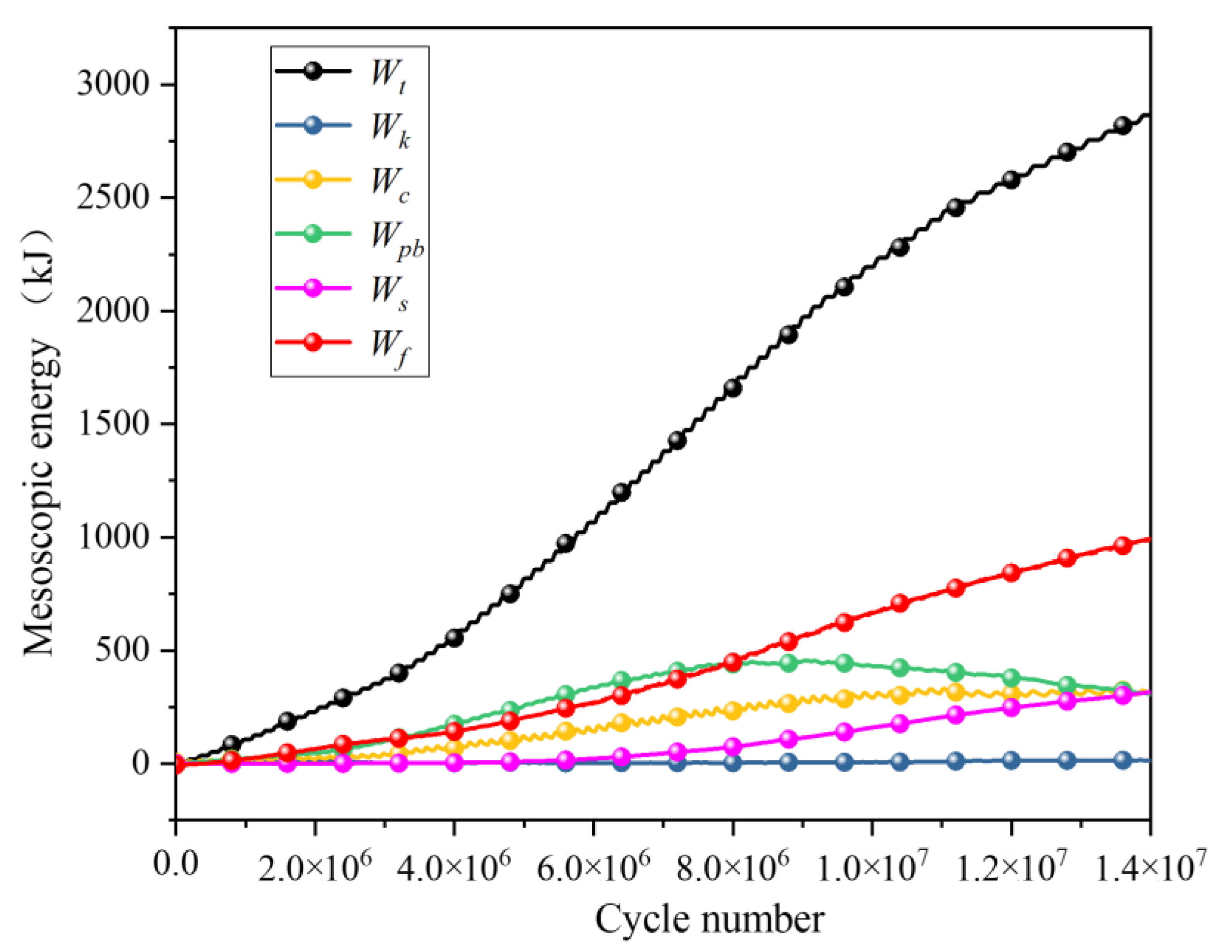
Under ultrasonic vibration load, a compressive stress-dominated stress concentration zone forms beneath the load surface and extends downwards. The degree of stress concentration decreases with increasing distance from the excitation surface. Internal kinetic energy generated within the rock is minimal; instead, primary sources of energy include particle strain energy, parallel bond strain energy, frictional energy, and plastic deformation energy. The curve representing energy dissipation coefficient exhibits an initial increase followed by a decrease before eventually increasing again.
(3)
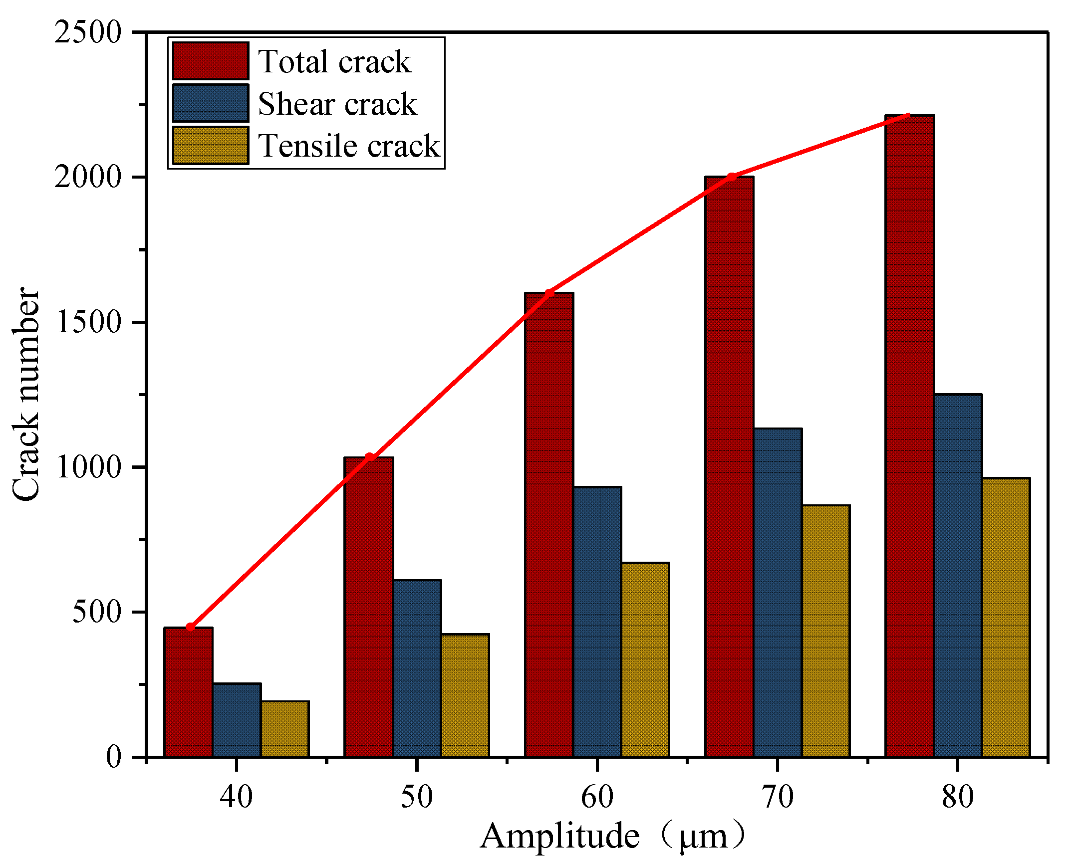
The deformation, fracture, and energy evolution characteristics of the rock under the five different amplitudes are compared and analyzed. The results demonstrate that while amplitude variations do not affect the maximum displacement value of the rock, they do accelerate its deformation rate. As the maximum displacement within the rock reaches its limit deformation value, increasing the amplitude expands the range of maximum deformation. Moreover, there exists a proportional relationship between amplitude changes and rock fragmentation, crack propagation, as well as energy dissipation coefficient. Increasing the amplitude contributes to enhancing rock breaking efficiency. Under an equal number of cycle steps (5,000,000 cycles), when increasing from 40 μm to 80 μm in amplitude, fracture volume, crack count, and energy dissipation coefficient increase by 429.67%, 494.44%, and 19.272% respectively.

Author Contributions

All the authors contributed to publishing this paper. X.W. and L.Z. conceived and designed the research. L.Z. performed the experiments and wrote the original manuscript. Z.N. and J.D. participated in the data analysis and manuscript modification. All authors have read and agreed to the published version of the manuscript.

Funding

This research was funded by the National Natural Science Foundation of China, (52374146, 51874282), and the Six Talent Peaks Project in Jiangsu Province (GDZB-052).

Data Availability Statement

Data is contained within the article.

Acknowledgments

Great appreciation goes to the editorial board and the reviewers of this paper.

Conflicts of Interest

The authors declare no conflict of interest.

References

  1. Chang, Z.; Sherrit, S.; Bao, X.; Bar-Cohen, Y. Design and analysis of ultrasonic horn for USDC (ultrasonic/sonic driller/corer). Smart Struct. Mater. 2004 Ind. Commer. Appl. Smart Struct. Technol. 2004, 5388, 320–326. [Google Scholar]
  2. Bar-Cohen, Y.; Bao, Z.; Chang, Z.; Sherrit, S. An ultrasonic sampler and sensor platform for in-situ astrobiological exploration. Smart Struct. Mater. 2003 Smart Struct. Integr. Syst. 2003, 5056, 457–465. [Google Scholar]
  3. Bagde, M.N.; Petros, V. Fatigue properties of intact sandstone samples subjected to dynamic uniaxial cyclical loading. Int. J. Rock Mech. Min. Sci. 2005, 42, 237–250. [Google Scholar] [CrossRef]
  4. Wiercigroch, M.; Wojewoda, J.; Krivtsov, A.M. Dynamics of ultrasonic percussive drilling of hard rocks. J. Sound Vib. 2005, 280, 739–757. [Google Scholar] [CrossRef]
  5. Wang, H.; Li, J. Mechanical Behavior Evolution and Damage Characterization of Coal under Different Cyclic Engineering Loading. Geofluids 2020, 2020, 8812188. [Google Scholar] [CrossRef]
  6. Liu, B.; Zhao, Y.; Hua, X.; Ling, C.; Wang, X. Failure characteristic and acoustic emission spatio-temporal evolution of coal under different cyclic loading rates. Energy Sci. Eng. 2023, 11, 2039–2051. [Google Scholar] [CrossRef]
  7. Geranmayeh Vaneghi, R.; Ferdosi, B.; Okoth, A.; Kuek, B. Strength degradation of sandstone and granodiorite under uniaxial cyclic loading. J. Rock Mech. Geotech. Eng. 2018, 10, 117–126. [Google Scholar] [CrossRef]
  8. Erarslan, N.; Alehossein, H.; Williams, D.J. Tensile Fracture Strength of Brisbane Tuff by Static and Cyclic Loading Tests. Rock Mech. Rock Eng. 2013, 47, 1135–1151. [Google Scholar] [CrossRef]
  9. Liu, J.; Qin, G.; Cao, J.; Zhai, M. Analysis Deformation Failure Characteristics and the Energy Evolution of Varying Lithologies under Cyclic Loading. Geofluids 2022, 2022, 7984910. [Google Scholar] [CrossRef]
  10. Fan, L.; Qiu, B.; Cao, J.; Du, X. A Real-Time Visual Investigation on Microscopic Progressive Fatigue Deterioration of Granite Under Cyclic Loading. Rock Mech. Rock Eng. 2023, 56, 5133–5147. [Google Scholar] [CrossRef]
  11. Erarslan, N.; Williams, D. The damage mechanism of rock fatigue and its relationship to the fracture toughness of rocks. Int. J. Rock Mech. Min. Sci. 2012, 56, 15–26. [Google Scholar] [CrossRef]
  12. Li, W.; Yan, T.; Li, S.; Zhang, X. Rock fragmentation mechanisms and an experimental study of drilling tools during high-frequency harmonic vibration. Pet. Sci. 2013, 10, 205–211. [Google Scholar] [CrossRef]
  13. Li, S.; Tian, S.; Li, W.; Ling, X.; Kapitaniak, M.; Vaziri, V. Numerical study on the elastic deformation and the stress field of brittle rocks under harmonic dynamic load. Energies 2020, 13, 851. [Google Scholar] [CrossRef]
  14. Yin, S.; Zhao, D.; Zhai, G. Investigation into the characteristics of rock damage caused by ultrasonic vibration. Int. J. Rock Mech. Min. Sci. 2016, 84, 159–164. [Google Scholar] [CrossRef]
  15. Zhou, Y.; Tang, Q.; Zhang, S.; Zhao, D. The Mechanical Properties of Granite under Ultrasonic Vibration. Adv. Civ. Eng. 2019, 2019, 9649165. [Google Scholar] [CrossRef]
  16. Zhang, L.; Wang, X.; Wang, J.; Yang, Z. Mechanical characteristics and pore evolution of red sandstone under ultrasonic high-frequency vibration excitation. AIP Adv. 2021, 11, 055202. [Google Scholar] [CrossRef]
  17. Zhang, L.; Wang, X.; Wang, J.; Yang, Z. Research on Fracture Characteristics and Energy Dissipation of Hard Rock under the Excitation of Ultrasonic Vibration. Geofluids 2022, 2022, 8351316. [Google Scholar] [CrossRef]
  18. Wang, Y.; Cui, F. Energy evolution mechanism in process of Sandstone failure and energy strength criterion. J. Appl. Geophys. 2018, 154, 21–28. [Google Scholar] [CrossRef]
  19. Yang, S.; Tian, W.; Huang, Y.; Ranjith, P.; Ju, Y. An Experimental and Numerical Study on Cracking Behavior of Brittle Sandstone Containing Two Non-coplanar Fissures Under Uniaxial Compression. Rock Mech. Rock Eng. 2016, 49, 1497–1515. [Google Scholar] [CrossRef]
  20. Li, X.; Li, H.; Liu, Y.; Zhou, Q.; Xia, X. Numerical simulation of rock fragmentation mechanisms subject to wedge penetration for TBMs. Tunn. Undergr. Space Technol. 2016, 53, 96–108. [Google Scholar] [CrossRef]
Figure 1. Particle distribution.
Processes 12 00074 g001
Figure 2. Parallel bond model.
Processes 12 00074 g002
Figure 3. (a) Comparison of stress-strain curves; (b) Failure mode comparison.
Processes 12 00074 g003
Figure 4. The change of displacement distribution cloud map.
Processes 12 00074 g004
Figure 5. (a) Evolution of maximum displacement; (b) Evolution of minimum displacement.
Processes 12 00074 g005
Figure 6. Rock fracture and crack propagation process.
Processes 12 00074 g006
Figure 7. Crack number evolution.
Processes 12 00074 g007
Figure 8. Contact force distribution.
Processes 12 00074 g008
Figure 9. Force chain distribution.
Processes 12 00074 g009
Figure 10. Energy evolution curve.
Processes 12 00074 g010
Figure 11. Evolution curve of energy dissipation coefficient.
Processes 12 00074 g011
Figure 12. Rock breakage at different amplitudes.
Processes 12 00074 g012
Figure 13. Evolution of rock fragmentation under different amplitudes.
Processes 12 00074 g013
Figure 14. (a) The number of shear cracks varies with different amplitudes; (b) The number of tensile cracks varies with different amplitudes.
Processes 12 00074 g014
Figure 15. The number of cracks produced by different amplitudes under the same number of cycles.
Processes 12 00074 g015
Figure 16. Evolution curve of maximum displacement.
Processes 12 00074 g016
Figure 17. (a) Strain energy evolution under different amplitudes; (b) Evolution of dissipated energy at different amplitudes.
Processes 12 00074 g017
Figure 18. Evolution of energy dissipation coefficients under different amplitudes.
Processes 12 00074 g018
Table 1. Mesoscopic parameters of numerical models.
Particle density/(kg/m3)Particle stiffness ratioparallel bond modulus/(GPa)
27001.54.5
Particle contact modulus (GPa)Friction coefficientparallel bond stiffness ratio
4.80.52.5
Tangential bond strength (MPa)Normal bond strength (MPa)parallel bond radius factor
45371
Disclaimer/Publisher’s Note: The statements, opinions and data contained in all publications are solely those of the individual author(s) and contributor(s) and not of MDPI and/or the editor(s). MDPI and/or the editor(s) disclaim responsibility for any injury to people or property resulting from any ideas, methods, instructions or products referred to in the content.

