Article

Experimental Assessment of a Decentralized Control Strategy for a Back-to-Back Modular Multilevel Converter Operating in Low-Frequency AC Transmission

1
Electrical Engineering Department, University of Santiago of Chile, Santiago 9170020, Chile
2
Department of Mechatronic Engineering, Instituto Tecnologico de Costa Rica, Cartago 30109, Costa Rica
3
Electrical Engineering Department, University of Chile, Santiago 8820808, Chile
4
Faculty of Engineering, Universidad San Sebastian, Santiago 7510602, Chile
*
Author to whom correspondence should be addressed.
Processes 2024, 12(1), 155; https://doi.org/10.3390/pr12010155
Submission received: 12 December 2023 / Revised: 30 December 2023 / Accepted: 2 January 2024 / Published: 9 January 2024
(This article belongs to the Special Issue Energy Process Systems Simulation, Modeling, Optimization and Design)

Abstract

:
The Modular Multilevel Converter (MMC) has been widely used in high-power applications owing to its inherent advantages, including scalability, modularity, high-power density, and fault tolerance. MMCs have recently been used in Low-Frequency Alternating Current (LFAC) transmission, particularly in the integration of offshore wind power with onshore grids. However, LFAC applications produce significant voltage oscillations in floating capacitor voltages within the MMC. Early research efforts have successfully established and validated decoupled control strategies for LFAC-based MMC systems. However, validations are usually based on simulations or small-scale prototypes equipped with limited power cells. Consequently, this paper presents a decentralized voltage control strategy based on Nearest Level Control for an MMC-based LFAC system. Experimental results obtained with a 120-cell MMC prototype are presented to validate the effectiveness and operation of the MMC in LFAC applications.

1. Introduction

Wind energy is a key technology to transition to sustainable and clean energy generation. In 2023, the Global Wind Energy Council reported a remarkable growth in wind energy capacity with the addition of 100 GW worldwide, which was a 15% increase compared to the previous year. Key global markets, such as China, the US, Brazil, Germany and Sweden, represented 71% of the total of wind energy installations [1]. The projections of the GWEC expect an impressive 680 GW of new capacity to be integrated in the next seven years (2023–2030). This implies adding 143 GW of new capacity per year, reaching 1221 GW by 2030. Most of this new capacity will be installed in Offshore Wind Power Plants (OWPPs), as offshore installations offer more wind energy resources, maximize energy generation, help mitigate visual and noise impacts on the land, and help the stability of the grid [2]. Therefore, the integration of efficient and cost-effective transmission systems for OWPPs is an important topic in research and industry.
Conventionally, OWPPs are connected to the onshore grid using 50–60 Hz high-voltage AC (HVAC) or high-voltage DC (HVDC) transmission systems [3]. HVAC transmission systems operate efficiently over long distances when installed overhead. However, its efficiency decreases as the distance increases, particularly when using submarine cables. Therefore, HVDC transmission systems have been widely adopted for OWPP connections, as they can minimize power losses over submarine cables. However, the cost of HVDC systems is a limiting factor due to the need for offshore substations and rectifiers [4]. Modular Multilevel Converters (MMCCs) are preferred in high-voltage current converters because they operate at high voltage, are highly expandable, have high power quality and controllability, and are fault-tolerant. For example, MMCC-based HVDC transmission systems in Europe have a capacity of 5 GW, while the capacity in China is 3.1 GW [5,6].
The application of low-frequency AC (LFAC) systems has been suggested as an attractive solution to both HVAC and HVDC [7,8,9,10,11]. LFAC was originally introduced to the railway industry a century ago. Later, it was applied to OWPPs, as it allows for greater cost savings because of the increased maximum transferable active power compared to HVAC. Additionally, it eliminates the need for a converter at the offshore substation, which is required in the case of HVDC transmission systems. A typical LFAC OWPP is shown in Figure 1, which is composed of an offshore substation, a submarine cable, and an onshore substation. The OWPP operates in low-frequency ratios around 1–20 Hz to maximize power transference. Then, voltage source converters, usually MMCCs, are used in the onshore substation to connect the low-frequency to the 50 or 60 Hz grid.
The most widely used and mature converter among MMCCs is the Marquart converter [12], which is also called a Modular Multilevel Converter (MMC). The MMC comprises six AC–DC conversion clusters, as shown in Figure 2. Each cluster comprises cascaded power cells connected to an inductor, generally half-bride or full-bridge power cells. When AC–AC conversion is necessary, a Back-to-Back (B2B) connection of two MMCs is used [13]. As external sources do not impose voltages on each cell, the capacitors could be charged or discharged during the operation of the converter. Therefore, complex control strategies are required in low-frequency applications [14], which reduces the efficiency of the MMC.
Several research proposals have discussed the design and control of MMC-based LFAC systems. On the one hand, control strategies for B2B MMC have been introduced [15,16,17]. On the other hand, other MMC topologies have been proposed, such as the Hexverter and Modular Multilevel Matrix Converter [18,19,20]. Most of the research proposed in these articles does not consider controlling the voltage imbalance between clusters.
Furthermore, simulations with simplified MMC models [15,16,17], or experimental implementations that use a reduced number of power cells [21,22], are mainly considered. These experimental prototypes usually have between two and four power cells per cluster. Therefore, implementation issues such as non-linearity in power cells, imbalances in grid voltages, offsets in the measurements, and voltage balancing with an elevated number of power cells are still challenging for LFAC applications. Recently, variable-speed control strategies for MMC use decoupled transformations, usually called Σ Δ transformation [23,24], to regulate the floating capacitor as a function of the circulating currents of the MMC. Control strategies based on circulating current control have some drawbacks related to negative effects on efficiency and increase the built-in converter ratio [25,26]. Moreover, circulating current control requires a centralized control system and can have implementation restrictions when a large number of power cells are considered [27].
This paper proposes a decentralized control strategy for a B2B MMC that operates in LFAC applications. The proposed control strategy regulates the voltage oscillations produced by the LFAC systems without relying on circulating current control. The proposed control strategy integrates a Nearest Level Control (NLC) technique with a sorting algorithm, providing proper voltage balancing regulation regardless of the input–output port frequencies.
The effectiveness of the proposed control strategy is validated using a B2B MMC prototype composed of 120 power cells. The experimental setup utilized state-of-the-art OPAL-RT real-time controllers for the implementation of both the control and power stages, which was complemented by dedicated power sources. The experimental results obtained from this 120-power cell MMC prototype serve as empirical evidence of the correct functioning of the proposed control strategy, showcasing its potential for practical implementation in LFAC systems with a large number of power cells due to its decentralized nature.
The rest of the paper is organized as follows. Section 2 presents the modeling of a typical MMC-based LFAC system considering the decoupled model of the MMC. The control strategy is then described in Section 3. The experimental results obtained with a 120-power cell prototype are discussed in Section 4. Finally, the conclusions and future work are discussed at the end of the paper.

2. Modeling of the MMC

MMC modeling relates its currents, voltages and power components, which are expressed in a natural frame (that is, in a b c ) or in a decoupled frame. Using decoupled modeling, the floating capacitor voltages are related to the internal currents of the converter, called circulating currents, to enable a decoupled representation. In the following subsections, the voltage–current and voltage–power models of the MMC are discussed using a decoupled modeling approach [24].

2.1. Voltage–Current Model

Figure 2 illustrates a typical B2B configuration of two MMCs that interconnect a low-frequency (LF) system with a high-frequency (HF) system. Each grid has an impedance indicated by R HF for the HF port and R HF and L HF for the 50 Hz port. The phases of the LF port are indicated by the subindex x { r , s , t } , and the phases of the HF port are indicated by y { a , b , c } . The MMC clusters are labeled positive P and negative N. Each cluster comprises n floating half-bridge cells connected in series with an inductor. The positive and negative poles of each MNMC are connected to a common DC port. Phase-neutral AC voltages v x , v y and phase currents in LF and HF ports are defined as follows:
v r = V p , 1 cos ( ω LF t ) v s = V p , 1 cos ω LF t 2 π 3 v t = V p , 1 cos ω LF t + 2 π 3
i r = I p , 1 cos ( ω LF t φ 1 ) i s = I p , 1 cos ω LF t 2 π 3 φ 1 i t = I p , 1 cos ω LF t + 2 π 3 φ 1
v a = V p , 2 cos ( ω HF t ) v b = V p , 2 cos ω HF t 2 π 3 v c = V p , 2 cos ω HF t + 2 π 3
i a = I p , 2 cos ( ω HF t φ 2 ) i b = I p , 2 cos ω HF t 2 π 3 φ 2 i c = I p , 2 cos ω HF t + 2 π 3 φ 2
where V p , 1 , V p , 2 , I p , 1 , I p , 2 are the peak values of voltages and currents; ω LF , ω HF stand for the angular frequency of the LF and HF ports; and φ 1 , φ 2 represent the shift angles.
Taking into account the B2B MMC circuit shown in Figure 2, it is possible to represent the voltages and currents of both ports as follows:
v r v s v t = v r P + v r N v s P + v s N v t P + v t N + R LF i r i s i t + L LF d d t i r i s i t + 2 L C d d t i c , 1 i c , 2 i c , 3 + v dc 1 1 1
v a v b v c = v r P + v a N v b P + v b N v c P + v c N + R HF i a i b i c + L HF d d t i a i b i c + 2 L C d d t i c , 4 i c , 5 i c , 6 + v dc 1 1 1
where v x P , v x N , v y P , v y N are the cluster voltage output; v d c is the DC port voltage; i d c is the DC port current; the cluster currents are defined as i x P , i x N , i y P , i y N ; and i c , 1 , i c , 2 , i c , 3 , i c , 4 , i c , 5 , i c , 6 are the cluster currents. By applying the Kirchhoff current law in the phases x { r , s , t } and y { a , b , c } , the AC ports currents can be estimated:
i r i s i t = i r P i r N i s P i s N i t P i t N ; i a i b i c = i a P i a N i b P i b N i c P i c N
i c , 1 i c , 2 i c , 3 = 1 2 i r P + i r N i s P + i s N i t P + i t N + 1 3 i d c i d c i d c ; i c , 4 i c , 5 i c , 6 = 1 2 i r P + i r N i s P + i s N i t P + i t N 1 3 i d c i d c i d c
Expressing (5) and (6) in synchronous reference frame and considering the previous expression of the cluster currents, the following equations are obtained:
v d , 1 v q , 1 v 0 , 1 = v d , 1 P + v d , 1 N v q , 1 P + v q , 1 N v 0 , 1 P + v 0 , 1 N + L LF d d t i d , 1 i q , 1 i 0 , 1 + v dc 0 0 1 + L C d d t i c d , 1 i c q , 1 i c 0 , 1 + R LF ω LF L LF 0 ω LF L LF R LF 0 0 0 1 i d , 1 i q , 1 i 0 , 1 + 0 ω LF L C 0 ω LF L C 0 0 0 0 1 i c d , 1 i c q , 1 i c 0 , 1
v d , 2 v q , 2 v 0 , 2 = v d , 2 P + v d , 2 N v q , 2 P + v q , 2 N v 0 , 2 P + v 0 , 2 N + L LF d d t i d , 2 i q , 2 i 0 , 2 + v dc 0 0 1 + L C d d t i c d , 2 i c q , 2 i c 0 , 2 + R HF ω HF L HF 0 ω HF L HF R HF 0 0 0 1 i d , 2 i q , 2 i 0 , 2 + 0 ω LF L C 0 ω LF L C 0 0 0 0 1 i c d , 2 i c q , 2 i c 0 , 2
The expressions in (9) and (10) represent independent dynamics for the AC and DC ports of each MMC. Therefore, i d , 1 , i q , 1 can be used to manipulate the active and reactive power in the LF port. Analogously, i d , 2 , i q , 2 can be used to regulate the power terms in the HF port.

2.2. Power-Voltage Model

Assuming a uniform cell capacitance C, an equal voltage distribution per cell v C * and neglecting cell losses, the equivalent Cluster Capacitor Voltage (CCV) is obtained by the sum of the cell voltages within a cluster:
C v C * d v C x P d t C i = 1 n d v C x , i P d t ; C v C * d v C x N d t C i = 1 n d v C x , i N d t
C v C * d v C y P d t C i = 1 n d v C y , i P d t ; C v C * d v C y N d t C i = 1 n d v C y , i N d t
Given the floating configuration of the half-bridge power cells within each group, they must be controlled to maintain a stable voltage v C * . This regulation is achieved by manipulating the cluster currents i x P , i x N , i y P , i y N , which also contain a component that provides power to the DC and AC ports. The power in each cluster, that is, p x P , p x N , p y P , p y N , is the product of the cluster currents and the corresponding output cluster voltages, such that p x P v x P · i x P , p y P v y P · i y P , p x N v x N · i x N , and p y N v y N · i y N . Then, the cluster currents are used as inputs to regulate the floating capacitor voltage in each cell.
The CCV in (11) and (12) can be expressed in terms of the cluster power as follows:
1 C v C * 0 t p r P p s P p t P p r N p s N p t N v C r P v C s P v C t P v C r N v C s N v C t N
v C x P v ¯ C x P + v ˜ C x P , v C x N v ¯ C x N + v ˜ C x N
1 C v C * 0 t p a P p b P p c P p a N p b N p c N v C a P v C b P v C c P v C a N v C b N v C c N
v C y P v ¯ C y P + v ˜ C y P , v C y N v ¯ C y N + v ˜ C y N
The CCVs terms are decomposed into oscillating terms v ˜ C x P , v ˜ C x N , v ˜ C y P , v ˜ C y N and average terms v ¯ C x P , v ¯ C x N , v ¯ C y P , v ¯ C y N . As is well known, to ensure proper balance in MMCs, the oscillating terms must be controlled to zero and the average CCV in each cluster must be greater than the input and output voltage [28]. v ¯ C x P , v ¯ C x N , v ¯ C y P , v ¯ C y N to n v C * .
In this paper, a balancing control is applied to regulate the average term in the CCV to a stable average v C * by manipulating i x P , i x N , i y P , i y N (see (13) and (15)). In this manner, the oscillating terms are not controlled with the advantage of reducing the peak of the cluster currents i c , 1 , , i c , 6 of (5) and (6).

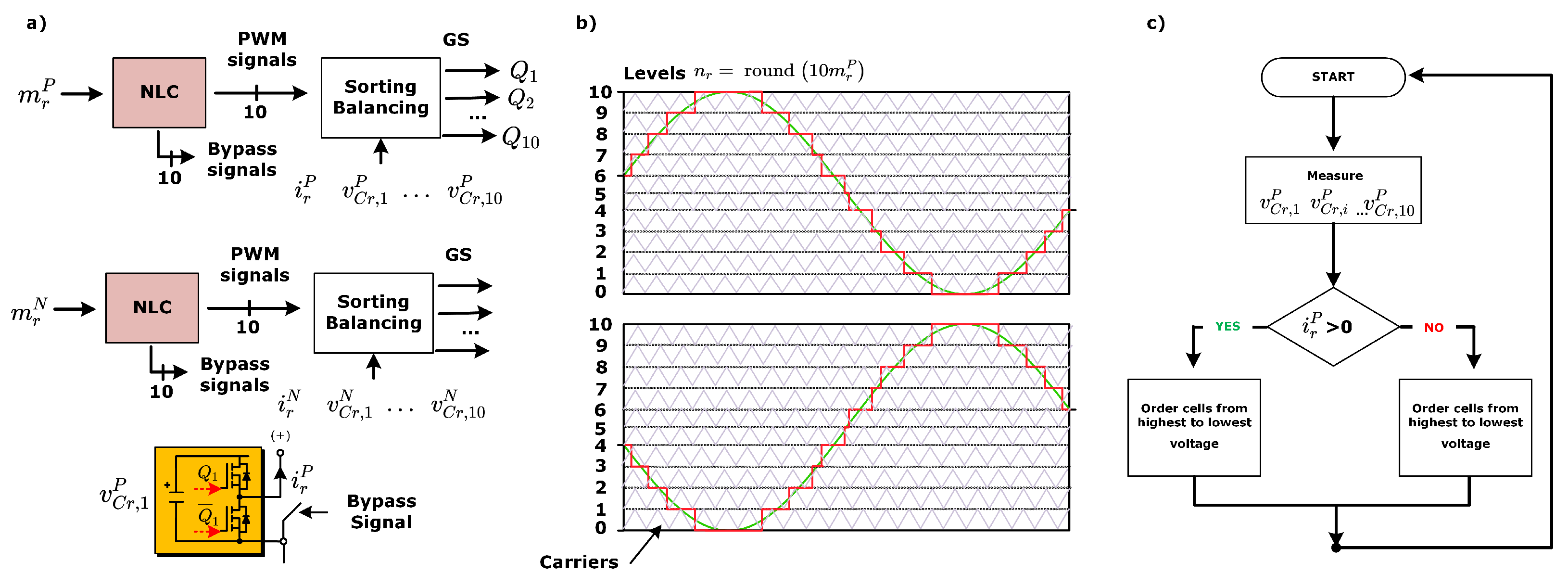
3. Proposed Control Strategy

The proposed control strategy is comprised of a nested structure using proportional integral (PI) controllers as shown in Figure 3. The LF port MMC is used to control the DC voltage and the reactive power by manipulating i d 1 and i q 1 . On the other hand, HF MMC is used to regulate active and reactive power by manipulating i d 2 and i q 2 . Measurements of the cluster currents i x P , i x N , i y P and i y N are used to calculate the currents at the LF port ( i r , i s , i t ) and at the HF port ( i a , i b , i c ). These currents are then transformed into a reference frame synchronized with the LF voltage v x and synchronized with the HF voltage v y . The estimation of the angles θ L F and θ H F are obtained using conventional phase-lock loop algorithms.
The relation between active power and DC voltage v d c is considered as follows.
P 1 = v d , 1 i d , 1 3 C 2 n v d c * d v d c d t
It is important to note that in the B2B configuration, an MMC regulates v d c through the direct component of the LF port current i d , 1 . Moreover, the inner current loops, based on PI control, regulate the aforementioned currents to their respective references, which are defined for the active and reactive power at the LF and HF ports as follows:
P 2 * = V p , 2 · i d , 2 * ; Q 2 * = V p , 2 · i q , 2 * Q 1 * = V p , 1 · i q , 1 *
where Q 1 * , P 2 * Q 2 * are the active and reactive power references for the LF port and the HF port, respectively. It is important to note that P 2 * is included as a feedforward term in the current control of the LF MMC even though this is not illustrated in Figure 3. As proposed in [28], this feedforward improves the dynamic response of a B2B MMC as the change in the power of one port is fed to the inner control loop of the other MMC. The inner current controllers generate voltage references in the frame d q that need to be transformed back to the natural frame. Then, the voltage reference is obtained for each cluster, that is, v r * , v s * , v t * , v a * , v b * , v c * . These references are normalized to obtain the modulation index as follows:
m r P * m s P * m t P * = 1 v dc / 2 v r P * v s P * v t P * + 1 1 1 ; m r N * m s N * m t N * = 1 v dc / 2 v r N * v s N * v t N * + 1 1 1
m a P * m b P * m c P * = 1 v dc / 2 v a P * v b P * v c P * + 1 1 1 ; m a N * m b N * m c N * = 1 v dc / 2 v a N * v b N * v c N * + 1 1 1
The local cell balancing and modulation block is presented in Figure 4 as proposed in [29,30,31]. First, the modulation indices m x P , m x N are directed to a Nearest Level Control (NLC), where cells are selected and added according to the level required to synthesize in the output. Otherwise, they are bypassed. The NLC includes the use of Pulse Width Modulation (PWM) signals compared to 4 kHz carriers, and a local balance control (LCB) that utilizes sorting logic to measure capacitor voltages per cluster [32,33,34]. The LCB ensures that cells are ordered from the lowest to the highest capacitor voltage or vice versa according to the direction of the cluster currents i x P , i x N , relative to the reference voltage v C * / n . Subsequently, gate signals are generated to drive the semiconductor devices in each cell with the application of PWM to the last inserted power cell.

4. Experimental Results

This section validates the proposed control strategy using a prototype of a 120 power cell B2B MMC that connects a 15 Hz grid to a 50 Hz grid. Details about the structure and main parameters of the prototype are provided. Then, three experimental tests are included to verify the operation of the proposed control strategy for bidirectional power flow and dynamic load variation. In all cases, experimental results are presented to verify the regulation of the voltages of the 120 DC capacitors, cluster currents and AC port voltages and currents.

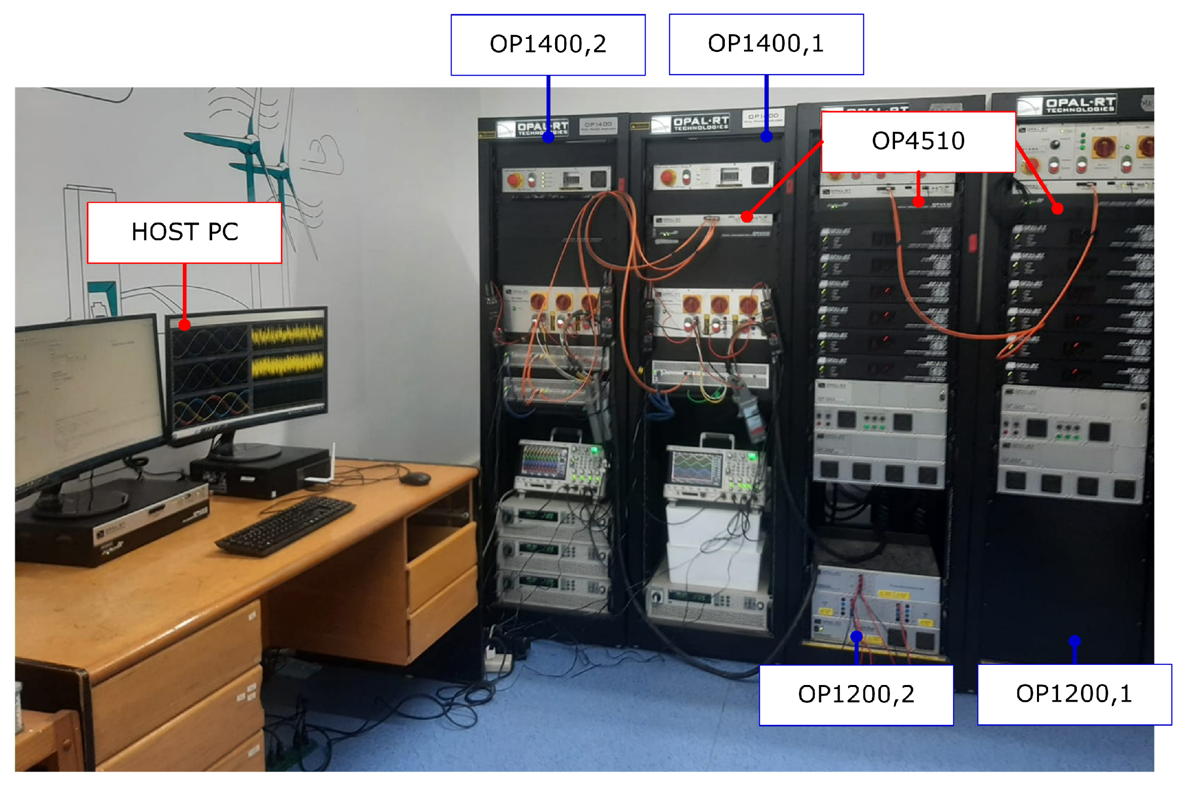
4.1. Prototype Description

The main structure of the prototype is shown in Figure 5. The prototype is composed of a host computer, two programmable AC power sources, and two 60-power cell MMCs from OPAL-RT. A photograph of the B2B MMC prototype is shown in Figure 6, and its main parameters are summarized in Table 1. The control system operates with a sample time of 250 μ s .
Each MMC OP1200 incorporates 60 full-bridge power cells. The control platform comprises a master and two slave Real-Time Simulators (RTSs) from OPAL-RT, model OP4510. The OP4510 is used as control stages to program the control strategy described in Figure 3 and Figure 4. The master RTS is connected to a host computer and configured to send the references v d c * , Q 1 * , P 2 * , Q 2 * to the slave RTS and regulate both MMCs. The master RTS receives the measurements of the electrical variables and provides a real-time visualization of these variables. The host computer runs the control strategy over RT-LAb and Simulink; then, all measurements can be accessed in real time and are plotted using Matlab figures. A third RTS is also used to control programmable AC power sources. The first MMC performs the V dc Q control, and the second MMC performs the PQ control. Programmable AC power sources operate at 120 V/15 Hz in the LF port and 120 V/50 Hz in the HF port.
The first MMC is regulated to control the DC voltage ( V dc ) and the reactive power (Q), while the second MMC is regulated to control the active and reactive power independently. Programmable AC power sources are calibrated to deliver an output of 120 V at a frequency of 15 Hz for the LF port and, similarly, 120 V at 50 Hz for the HF port, thus providing the necessary conditions for the operation of the MMCs.

4.2. Test 1: 3 kw Power Transference

Experimental results for a3 kW power transfer between the LF port and the HF port. The results are presented in Figure 7, Figure 8 and Figure 9. It is important to note that all waveforms are plotted within a time window of 0.1 s. AC voltages and currents on the LF side can be observed in Figure 7a and Figure 7b, respectively. As illustrated in Figure 7c,d, the DC voltage and current are regulated at 400 V and 7.5 A, respectively. Furthermore, both MMCs exhibit appropriate power tracking for active and reactive power as shown in Figure 7d,e.
Oscilloscope waveforms for this test are presented in Figure 8. HF and LF voltages and currents exhibit good power quality. The voltage regulation of the capacitor is presented in Figure 9, which shows the correct voltage regulation in the 120 power cells of the prototype. The 60 voltages of the cells in MMC1 are presented in Figure 9a, and the 60 voltages of the cells in MMC2 are presented in Figure 9c. As stated above, the ripple in the floating capacitor is indirectly proportional to the difference between the input and output frequencies of the MMC [22]. Therefore, the oscillations in the floating capacitors on the LF side are higher because of the AC–DC port frequency difference. In both cases, the capacitor voltages are properly regulated to an average value of 40 V despite the ripple components. Cluster currents show a DC component since they contain the power transference current (≈2.5 A) plus half of the alternating component of the LF and HF ports with an effective value of 3.75 A approximately (see Figure 9b,d).

4.3. Test 2: 3 kw Inverted Power Transference

The experimental results for an inverted power transfer are presented in Figure 10 and Figure 11. Figure 10a,b present AC voltages and currents at the LF port, exhibiting sinusoidal waveforms with low distortion. Stable DC voltage and current are achieved by LF MMC control, as shown in Figure 10c,d. Conversely, Figure 10e,f show the AC voltages and currents at the HF port, mirroring the expected sinusoidal profiles with higher frequency. Figure 10g,h present the active and reactive power for the LF and HF ports. These waveforms demonstrate that both MMCs maintain appropriate power tracking of active and reactive power.
The 120 cells are properly regulated at a mean voltage value of 40 V, and their fluctuations are bounded into a ripple lower than ≈12.5%, as shown in Figure 11a,c. Cluster currents have inverse mean values compared to the previous case (see Figure 11b,d).

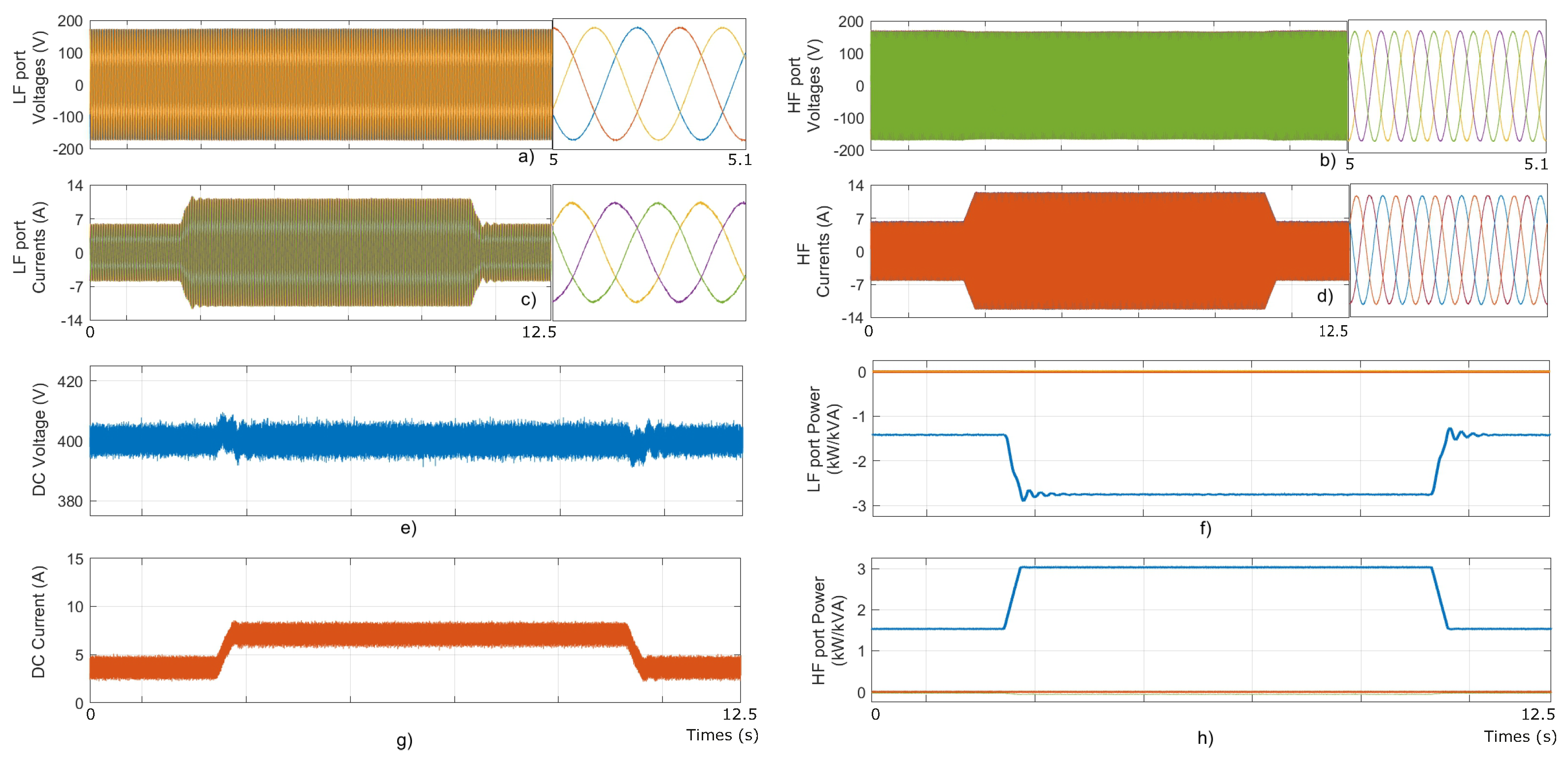
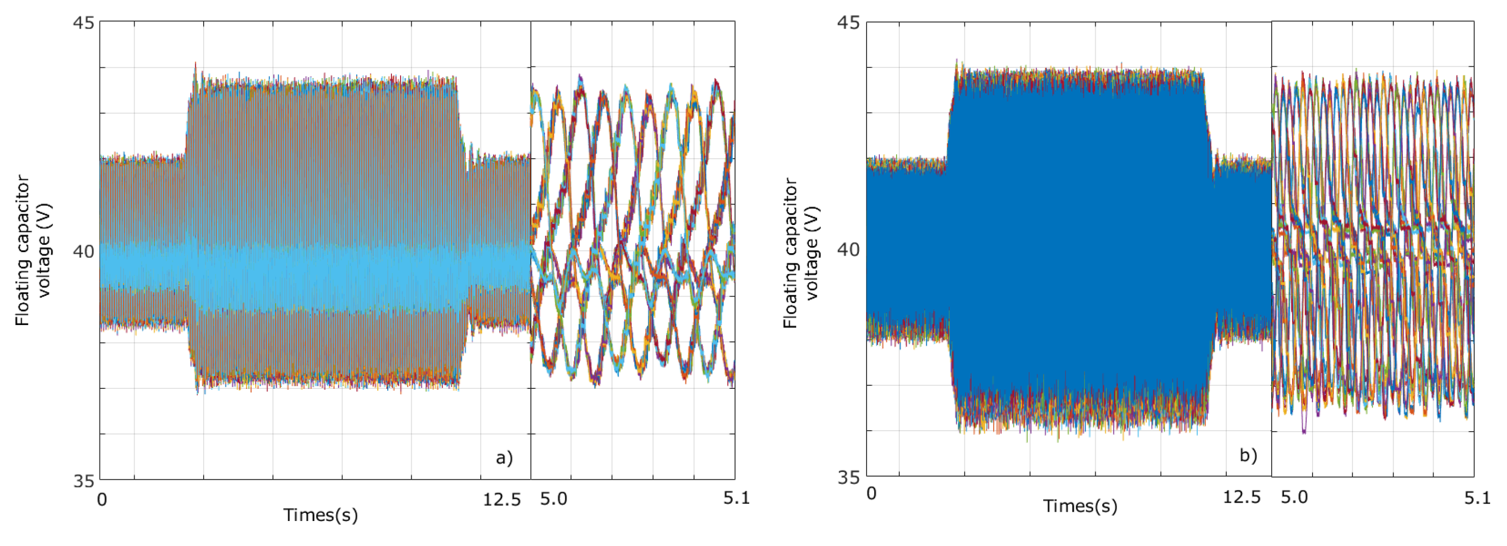
4.4. Test 3: Variations in Power Transference

In this test, the B2B is configured to change the power references. The results related to the AC ports are presented in Figure 12. AC voltages and currents in the LF port are presented in Figure 12a,b, while the voltages and currents in the HF port are presented in Figure 12c,d. An amplified view of voltages and currents is included in the figures to illustrate the frequencies at both ports. The DC voltage is regulated at 400 V, and the DC current reaches 7.5 A when the active power is duplicated. LF and HF port active and reactive power terms are presented in Figure 12f,h. Throughout the duration of the test, the B2B MMC maintains a unitary power factor at both ports. Initially, the system transferred 1.5 kW from the LF port to the HF port. Subsequently, at t 2 s, the power reference is increased to 3 kW, demonstrating the ability of the control to maintain the regulation of the voltages of the power cell capacitors regardless of the demands for power transfer.
The DC capacitor voltages of the 120 power cells are shown in Figure 13. The 60 DC capacitor voltages of the LF MMC are presented in Figure 13a, including an amplified view of the 60 voltages to visualize the oscillations caused by the 15 Hz grid. Similarly, Figure 13b shows the 60 DC capacitor voltages of the HF MMC. In this case, the oscillations are produced by the 50 Hz grid. In both cases, the voltages are controlled to a mean voltage value of 40 V. When active power is increased, voltage fluctuations are bounded in a ±4 V band in both ports.

5. Conclusions

This research paper proposes a new method for controlling a BTB MMC in LFAC applications. One of the challenges in these applications is the high-voltage oscillations in the floating capacitors of the MMC due to the LF in the AC port. The traditional approach of using circulating currents to mitigate these oscillations has some drawbacks, including reduced efficiency and limited application in high-number power cells.
Therefore, this paper introduces an NLC-based control strategy for a B2B MMC. This strategy enables proper voltage regulation in both MMCs without transformations or circulating currents. The NLC algorithm can properly control the floating capacitor while achieving decoupled power transfer on the LF and HF sides. The experimental results obtained with a prototype composed of 120 power cells are presented. In all tests, the results demonstrated proper voltage regulation between the voltages of the 120 floating capacitors, reduced cluster currents, and proper power quality in the AC ports.
Compared to state-of-the-art control strategies, the proposed control strategies eliminate the need for complex linear transformations, providing a simpler and easier implementation. Additionally, it does not use the circulating currents to regulate the floating capacitor voltages, mitigating drawbacks such as reduced efficiency. In addition, this strategy can be implemented in a decentralized manner. The RTSs used in the prototype do not need the information of the cluster measurements as they perform only outer control.
Future work is foreseen with the aim of further improving the performance of the control strategy performance and practical implementation. For example, it is possible to extend the research to investigate the scalability of the proposed control strategy for BTB MMCs in scenarios with an even higher number of power cells. In this regard, modified NLC strategies to enhance efficiency could be analyzed. In addition, it is possible to study the adaptability of the NLC-based control strategy to different operating conditions, such as varying loads and frequency fluctuations. Furthermore, future work could focus on developing robust security measures for the proposed control strategy.

Author Contributions

Conceptualization, M.D. and E.I.; methodology, S.R. and Y.A.; software, Y.A.; validation, E.I., M.D. and S.R.; formal analysis, J.R. and R.C.; writing—original draft preparation, E.I. and M.D.; writing—review and editing, E.I.; supervision, J.R. and R.C.; project administration, M.D. All authors have read and agreed to the published version of the manuscript.

Funding

This research was funded by the National Agency for Research and Development (ANID) through projects Fondequip EQM200234 and FONDECYT 1210208. Furthermore, the support of Vicerrectoría de Investigación, Innovación, y Creación (VRIIC), at the Universidad de Santiago de Chile through Project 062113DD-AYUDANTE is recognized.

Data Availability Statement

The data presented in this study are not available due to privacy.

Conflicts of Interest

The authors declare no conflict of interest..

References

  1. Global Wind Energy Counci. Global Wind Report 2023.Technical Report. Available online: https://gwec.net/globalwindreport2023/ (accessed on 1 September 2023).
  2. European Commission. Boosting Offshore Renewable Energy. Technical Report. 2020. Available online: https://ec.europa.eu/commission/presscorner/detail/en/IP_20_2096 (accessed on 1 September 2023).
  3. Rehman, A.; Koondhar, M.A.; Ali, Z.; Jamali, M.; El-Sehiemy, R.A. Critical Issues of Optimal Reactive Power Compensation Based on an HVAC Transmission System for an Offshore Wind Farm. Sustainability 2023, 15, 14175. [Google Scholar] [CrossRef]
  4. Xiang, X.; Merlin, M.; Green, T. Cost analysis and comparison of HVAC, LFAC and HVDC for offshore wind power connection. In Proceedings of the 12th IET International Conference on AC and DC Power Transmission (ACDC 2016), Beijing, China, 28–29 May 2016; Institution of Engineering and Technology: London, UK, 2016; pp. 1–6. [Google Scholar] [CrossRef]
  5. Li, Y.; Liu, H.; Fan, X.; Tian, X. Engineering practices for the integration of large-scale renewable energy VSC-HVDC systems. Glob. Energy Interconnect. 2020, 3, 149–157. [Google Scholar] [CrossRef]
  6. Cherix, N. Functional Description and Control Design of Modular Multilevel Converters: Towards Energy Storage Applications for Traction Networks; EPFL: Lausanne, Switzerland, 2015. [Google Scholar] [CrossRef]
  7. Guidi, G.; Fosso, O. Investment cost of HVAC cable reactive power compensation off-shore. In Proceedings of the 2012 IEEE International Energy Conference and Exhibition (ENERGYCON), Florence, Italy, 9–12 September 2012; pp. 299–304. [Google Scholar] [CrossRef]
  8. Koondhar, M.A.; Kaloi, G.S.; Saand, A.S.; Chandio, S.; Ko, W.; Park, S.; Choi, H.J.; El-Sehiemy, R.A. Critical Technical Issues with a Voltage-Source-Converter-Based High Voltage Direct Current Transmission System for the Onshore Integration of Offshore Wind Farms. Sustainability 2023, 15, 13526. [Google Scholar] [CrossRef]
  9. Rahman, S.; Khan, I.; Alkhammash, H.I.; Nadeem, M.F. A Comparison Review on Transmission Mode for Onshore Integration of Offshore Wind Farms: HVDC or HVAC. Electronics 2021, 10, 1489. [Google Scholar] [CrossRef]
  10. Ruddy, J.; Meere, R.; O’Donnell, T. Low Frequency AC transmission for offshore wind power: A review. Renew. Sustain. Energy Rev. 2016, 56, 75–86. [Google Scholar] [CrossRef]
  11. Ryndzionek, R.; Sienkiewicz, L. Evolution of the HVDC Link Connecting Offshore Wind Farms to Onshore Power Systems. Energies 2020, 13, 1914. [Google Scholar] [CrossRef]
  12. Lesnicar, A.; Marquardt, R. An innovative modular multilevel converter topology suitable for a wide power range. In Proceedings of the 2003 IEEE Bologna Power Tech Conference Proceedings, Bologna, Italy, 23–26 June 2003; Volume 3, p. 6. [Google Scholar] [CrossRef]
  13. Saeedifard, M.; Iravani, R. Dynamic performance of a modular multilevel back-to-back HVDC system. IEEE Trans. Power Deliv. 2010, 25, 2903–2912. [Google Scholar] [CrossRef]
  14. Akagi, H. Classification, terminology, and application of the modular multilevel cascade converter (MMCC). IEEE Trans. Power Electron. 2011, 26, 3119–3130. [Google Scholar] [CrossRef]
  15. Meere, R.; Ruddy, J.; McNamara, P.; O’Donnell, T. Variable AC transmission frequencies for offshore wind farm interconnection. Renew. Energy 2016, 103, 321–332. [Google Scholar] [CrossRef]
  16. Ma, J.; Dahidah, M.; Pickert, V.; Yu, J. Modular multilevel matrix converter for offshore low frequency AC transmission system. In Proceedings of the IEEE International Symposium on Industrial Electronics, Edinburgh, UK, 19–21 June 2017; IEEE: Piscataway, NJ, USA, 2017; pp. 768–774. [Google Scholar] [CrossRef]
  17. Al-Tameemi, M.; Miura, Y.; Liu, J.; Bevrani, H.; Ise, T. A novel control scheme for multi-terminal low-frequency AC electrical energy transmission systems using modular multilevel matrix converters and virtual synchronous generator concept. Energies 2020, 13, 747. [Google Scholar] [CrossRef]
  18. Diaz, M.; Cardenas, R.; Espinoza, M.; Rojas, F.; Mora, A.; Clare, J.C.; Wheeler, P. Control of Wind Energy Conversion Systems Based on the Modular Multilevel Matrix Converter. IEEE Trans. Ind. Electron. 2017, 64, 8799–8810. [Google Scholar] [CrossRef]
  19. Yuan, C.; Zhou, R.; Tong, M. Topologies and control of low-frequency alternating current for offshore wind farms based on modular multilevel matrix converter. J. Eng. 2019, 2019, 2271–2277. [Google Scholar] [CrossRef]
  20. Liu, S.; Wang, X.; Meng, Y.; Sun, P.; Luo, H.; Wang, B. A decoupled control strategy of modular multilevel matrix converter for fractional frequency transmission system. IEEE Trans. Power Deliv. 2017, 32, 2111–2121. [Google Scholar] [CrossRef]
  21. Diaz, M.; Cárdenas Dobson, R.; Ibaceta, E.; Mora, A.; Urrutia, M.; Espinoza, M.; Rojas, F.; Wheeler, P. An Overview of Applications of the Modular Multilevel Matrix Converter. Energies 2020, 13, 5546. [Google Scholar] [CrossRef]
  22. Diaz, M.; Cardenas, R.; Ibaceta, E.; Mora, A.; Urrutia, M.; Espinoza, M.; Rojas, F.; Wheeler, P. An Overview of Modelling Techniques and Control Strategies for Modular Multilevel Matrix Converters. Energies 2020, 13, 4678. [Google Scholar] [CrossRef]
  23. Espinoza, M.; Cárdenas, R.; Díaz, M.; Clare, J.C. An Enhanced dq-Based Vector Control System for Modular Multilevel Converters Feeding Variable-Speed Drives. IEEE Trans. Ind. Electron. 2017, 64, 2620–2630. [Google Scholar] [CrossRef]
  24. Kolb, J.; Kammerer, F.; Gommeringer, M.; Braun, M. Cascaded Control System of the Modular Multilevel Converter for Feeding Variable-Speed Drives. IEEE Trans. Power Electron. 2015, 30, 349–357. [Google Scholar] [CrossRef]
  25. Sun, P.; Tian, Y.; Pou, J.; Konstantinou, G. Beyond the MMC: Extended Modular Multilevel Converter Topologies and Applications. IEEE Open J. Power Electron. 2022, 3, 317–333. [Google Scholar] [CrossRef]
  26. Karwatzki, D.; Mertens, A. Generalized Control Approach for a Class of Modular Multilevel Converter Topologies. IEEE Trans. Power Electron. 2018, 33, 2888–2900. [Google Scholar] [CrossRef]
  27. Xia, B.; Li, Y.; Li, Z.; Konstantinou, G.; Xu, F.; Gao, F.; Wang, P. Decentralized Control Method for Modular Multilevel Converters. IEEE Trans. Power Electron. 2019, 34, 5117–5130. [Google Scholar] [CrossRef]
  28. Espinoza, M.; Cárdenas, R.; Díaz, M.; Mora, A.; Soto, D. Modelling and control of the modular multilevel converter in back to back configuration for high power induction machine drives. In Proceedings of the IECON 2016—42nd Annual Conference of the IEEE Industrial Electronics Society, Florence, Italy, 23–26 October 2016; IEEE: Piscataway, NJ, USA, 2016; pp. 5046–5051. [Google Scholar] [CrossRef]
  29. Rejas, M.; Mathe, L.; Dan Burlacu, P.; Pereira, H.; Sangwongwanich, A.; Bongiorno, M.; Teodorescu, R. Performance comparison of phase shifted PWM and sorting method for modular multilevel converters. In Proceedings of the 2015 17th European Conference on Power Electronics and Applications (EPE’15 ECCE-Europe), Geneva, Switzerland, 8–10 September 2015; pp. 1–10. [Google Scholar] [CrossRef]
  30. Meshram, P.M.; Borghate, V.B. A Simplified Nearest Level Control (NLC) Voltage Balancing Method for Modular Multilevel Converter (MMC). IEEE Trans. Power Electron. 2015, 30, 450–462. [Google Scholar] [CrossRef]
  31. Nguyen, M.H.; Kwak, S. Nearest-Level Control Method with Improved Output Quality for Modular Multilevel Converters. IEEE Access 2020, 8, 110237–110250. [Google Scholar] [CrossRef]
  32. Lee, J.; Kang, D.; Lee, J. A Study on the Improved Capacitor Voltage Balancing Method for Modular Multilevel Converter Based on Hardware-In-the-Loop Simulation. Electronics 2019, 8, 1070. [Google Scholar] [CrossRef]
  33. Ricco, M.; Mathe, L.; Hammami, M.; Franco, F.L.; Rossi, C.; Teodorescu, R. A Capacitor Voltage Balancing Approach Based on Mapping Strategy for MMC Applications. Electronics 2019, 8, 449. [Google Scholar] [CrossRef]
  34. Toh, C.L.; Norum, L. VHDL implementation of capacitor voltage balancing control with level-shifted PWM for modular multilevel converter. Int. J. Power Electron. Drive Syst. 2016, 7, 94. [Google Scholar] [CrossRef]
Figure 1. Conventional MMC topology based on half-bridge cells.
Processes 12 00155 g001
Figure 2. Simplified circuit of B2B MMC for LFAC transmission.
Processes 12 00155 g002
Figure 3. Nested control system for B2B MMC-based system.
Processes 12 00155 g003
Figure 4. (a) NLC and sorting–balancing algorithm. (b) NLC operation. (c) Sorting logic.
Processes 12 00155 g004
Figure 5. B2B MMC prototype schematic.
Processes 12 00155 g005
Figure 6. B2B MMC prototype photograph.
Processes 12 00155 g006
Figure 7. Experimental results for test 1. (a) LF port voltages. (b) LF port currents. (c) DC voltage and current, LF MMC. (d) Active and reactive power, LF port. (e) HF port voltages. (f) HF port currents. (g) DC voltage and current, HF MMC. (h) Active and reactive power, LF port.
Processes 12 00155 g007
Figure 8. Experimental results for test 1. (a) HF grid voltages and currents. (b) LF grid voltages and currents.
Processes 12 00155 g008
Figure 9. Experimental results for test 1. (a) MMC capacitor voltages, LF port. (b) Cluster currents, LF port. (c) MMC capacitor voltages, HF port. (d) Cluster currents, HF port.
Processes 12 00155 g009
Figure 10. Experimental results for test 2. (a) LF port voltages. (b) LF port currents. (c) DC voltage and current, LF MMC. (d) Active and reactive power, LF port. (e) HF port voltages. (f) HF port currents. (g) DC voltage and current, HF MMC. (h) Active and reactive power, LF port.
Processes 12 00155 g010
Figure 11. Experimental results for test 2. (a) MMC capacitor voltages, LF port. (b) Cluster currents, LF side. (c) MMC capacitor voltages, HF port. (d) Cluster currents, HF port.
Processes 12 00155 g011
Figure 12. Experimental results for test 3. (a) LF port voltages. (b) LF port currents. (c) HF port voltages. (d) HF port currents. (e) DC port voltage. (f) Active and reactive power, LF port. (g) DC port current. (h) Active and reactive power, HF port.
Processes 12 00155 g012
Figure 13. Experimental results for test 3. (a) MMC capacitor voltages, LF port. (b) MMC capacitor voltages, HF port.
Processes 12 00155 g013
Table 1. Prototype parameters.
ParameterValue
Active power3000 W
LF port voltage/freq.120 V/15 Hz
HF port voltage/freq.120 V/50 Hz
LF port current.7.5 A
HF port current7.5 A
DC port voltage400 V
DC port current7.5 A
Power cell capacitance6 mF
Cluster inductance2.5 mH
Number of cells per cluster10
Power cell voltage40 V
Switching frequency4 kHz
Disclaimer/Publisher’s Note: The statements, opinions and data contained in all publications are solely those of the individual author(s) and contributor(s) and not of MDPI and/or the editor(s). MDPI and/or the editor(s) disclaim responsibility for any injury to people or property resulting from any ideas, methods, instructions or products referred to in the content.

