Article

Comparison of Two Lab Simulation Methods of Multiple Heavy Metal Contamination on FCC Catalysts

1
School of Petrochemical Engineering, Lanzhou University of Technology, No. 287 Langongping Road, Qilihe District, Lanzhou 730050, China
2
Lanzhou Petrochemical Research Center, PetroChina Petrochemical Research Institute, No. 1 Heshuibei Road, Xigu District, Lanzhou 730060, China
*
Authors to whom correspondence should be addressed.
Processes 2023, 11(7), 2014; https://doi.org/10.3390/pr11072014
Submission received: 11 May 2023 / Revised: 23 June 2023 / Accepted: 3 July 2023 / Published: 5 July 2023
(This article belongs to the Section Chemical Processes and Systems)

Abstract

:
Qualitative and quantitative description are key to solving the problem of heavy metal contamination on fluid catalytic cracking (FCC) catalysts. The loading efficiencies for different metals were compared for the two lab simulation methods of Multi-Cyclic Deactivation (MCD) and Advanced Catalyst Evaluation (ACE), and the microcatalytic performance of metal-contaminated catalysts was evaluated using an ACE Model C device. The results show that the MCD and ACE methods both obtain extremely high data accuracy, indicating that they can be used to ensure the parallel reliability of experimental results. The typical operating parameters for hydrothermal aging and metals loading can be adjusted to suit different metal types and content targets for either of these two simulation methods. Compared with an equilibrium catalyst from an industrial unit, the MCD method has the advantages of basic hydrothermal aging treatment with less metal loading efficiency, while the ACE method has an accurate metal amount and high loading efficiency for metal contamination, with a metal balance recovery rate above 99.5% at similar activation to the equilibrium catalyst. When used with a reasonable and effective metal pretreatment scheme, these two laboratory simulation methods can be used to evaluate new commercial catalysts and in fundamental experiments for the improvement of FCC catalysts for removal of metal contamination.

1. Introduction

Fluid catalytic cracking (FCC) technology has been and remains one of the most important processes in the petroleum refinery industry for transforming heavy fractions to more valuable fuels such as gasoline, diesel, liquefied petroleum gas (LPG), olefinic gases, and other products [1,2]. In recent years, with an increase in the degree of deterioration of crude oil, a large number of metals, such as vanadium [3,4], nickel [5,6], iron [7,8], sodium [9,10], etc., have been deposited on FCC catalysts, which causes the activity of the FCC catalyst to decrease and significantly changes the product distribution of the FCC reaction, causing serious economic losses to the enterprise [11]. Therefore, it is imperative to investigate this metal contamination and accelerate the improvement of FCC catalysts with higher metal capacities.
To understand the role of metal contamination, metal loading is a key factor in catalyst inactivation, and its accurate description is key to solving the problem of heavy metal contamination. However, its qualitative and quantitative analysis is extremely complex [12]. The strong impact of the FCC catalyst on the global performance of the commercial unit and its profitability justifies the effort to guarantee the use of the best formulation available, and creates demand for proper catalyst testing methodologies. Moreover, efficient catalyst and process development calls for a suitable laboratory tool to help in making evaluation as close to reality as possible. The high complexity and extreme magnitude of the commercial process severely complicate its faithful reproduction in the laboratory. Studies have shown that the content and presence of metals in the laboratory are quite different from industrial equilibrium catalyst agents (E-Cats), especially for heavy metals such as V, Ni, Fe, etc., making it important to develop effective heavy metal loading methods [13]. At present, there are a number of standard methods used in the laboratory to simulate industrial equilibrium agents, mainly the Mitchell Incipient Wetness Impregnation (MI), Cyclic Metal Deposition (CMD), Cyclic Propylene Steaming (CPS), and the Engelhard Transfer (ETM) methods. Buurmans et al. [14] investigated the effect of nickel and vanadium deactivation on the structure and acidity of FCC catalyst particles using steaming cyclic deactivation and the Mitchell impregnation method. Etim et al. [15] investigated the influence of residual catalyst acidity on catalytic products. The Mitchell (MI) method of simulating metal-poisoned catalysts exaggerates both the industrial E-Cat properties and the catalytic behavior, especially at high loadings. Nguyen et al. [16] investigated the effect of hydrothermal conditions on the catalytic deactivation of an FCC catalyst using a cyclic propylene steaming method. Implementation of CDM and CPS methods is very difficult and time-consuming, and there is a deviation in coke and gas yield [17,18,19]. Lerner et al. [20] investigated the assessment of deactivation from vanadium interaction with Fluid Catalytic Cracking Catalyst using ETM. However, there is no mature technical platform for evaluating the impact of catalysts on the device; the existing catalyst technical service platform module has simple functions and insufficient data contrast, meaning that the above methods have never been able to achieve an effective match between the metal content and category of laboratory catalysts and industrial E-Cats.
Multi-Cyclic Deactivation (MCD) is currently the closest laboratory heavy metal pollution simulation pretreatment method to the actual operating conditions of the industry. The core principle is to use raw oil configured with organic compounds of heavy metal as the simulation oil and to achieve contact reaction between the catalyst and the raw oil in a fixed fluidized bed reactor. Heavy metals are deposited on the surface of the catalyst through a cracking reaction, then the catalyst activity is restored through a regeneration process with water vapor, meanwhile achieving hydrothermal aging of the catalyst. This reaction regeneration process is recorded as a cycle. After a long period of multiple cycles, the final target heavy metal amount can be deposited on the catalyst. Control of the valence state and distribution position of heavy metals on the catalyst can be achieved through multiple cycles of redox postprocessing. Liao et al. [13] investigated the simulation of iron contamination in the laboratory. The multi-channel cyclic aging device MCD package consists of four reactors (i.e., four channels), each of which can operate independently of each other and be installed in a framework that shares utilities, supervisory control, and data acquisition. Each channel includes a fluidized bed reactor, independent intake system, deionized water vapor generation system, feed oil supply system, gas product condensation system, and common circuit system and feed oil pump heating system. The deactivation of the FCC catalyst in an MCD unit is a simulation of the deactivation processes in a commercial plant. Using a MCD multi-channel cyclic aging device, it is possible to obtain a better understanding of the deactivation behavior of FCC catalysts.
Advanced Catalyst Evaluation (ACE) is a new method of catalyst metalation developed using a spray impregnation technique [21]. It is recognized for its high degree of automation, low required dosage of agents/oils, short time consumption, and the ability to conduct six parallel experiments at once, achieving a leap from laboratory to industrialization for exploring and studying the amplification effect in the catalyst preparation process. The primary advantages are the need for only a small amount of materials (both raw materials and catalysts) and good reproducibility. ACE devices have gained recognition due to their high quality and good heat transfer characteristics. The various functional catalysts developed in the laboratory adopt simulated treatment methods, to ensure that they can be as close as possible to the industrial equilibrium agent in terms of their physical and chemical performance indicators and product distribution after the treatment reaction; this allows the use effect of the functional catalyst in the device to be predicted, providing accurate guidance for industrial operation.
Because the hydrothermal effect and metals deposition are two main factors that influence catalyst deactivation in commercial FCC units, the typical operating parameters for hydrothermal aging and metals loading are key to simulating E-Cats in the laboratory. The MCD and ACE methods are the laboratory simulation pretreatment methods for heavy metal contamination that can currently preset these operating parameters closest to actual industrial devices. Therefore, in order to accurately describe both loading characteristics and efficiency, MCD and ACE have been introduced as pretreatment methods for heavy metal contamination simulation in the laboratory to investigate the influence of different loading methods. In this way, characterization data are compared with the data of the equilibrium catalyst (E-Cat) collected from an industrial unit. A reasonable and effective metal pretreatment scheme is expected through screening and optimization processing, which provides reliable experimental data for the analysis of the heavy metal loading mechanism. After a digital evaluation system for FCC catalysts is established to replace the pilot test on the basis of shortening the product evaluation cycle and evaluation costs, the lab simulation methods and their evaluation data can be used to enhance the competitiveness of catalysts in bidding.

2. Experiments

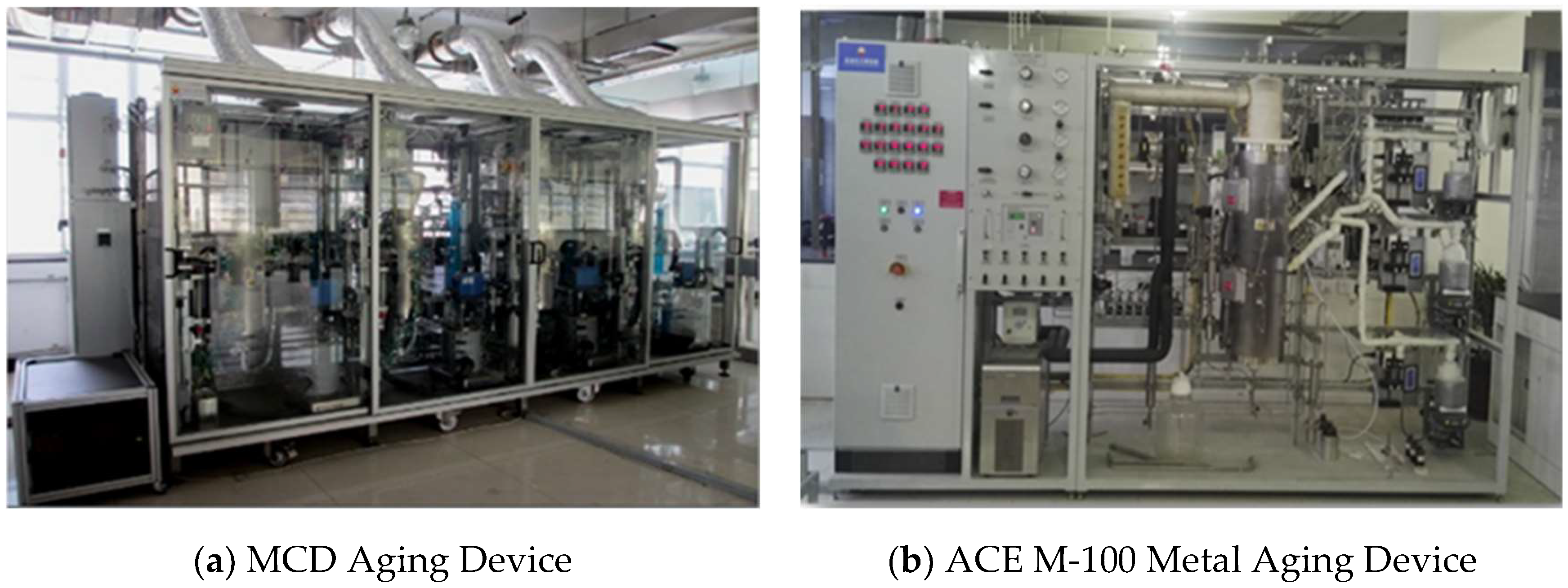
2.1. Experimental Device

An advanced MCD device was used to simulate an industrial FCC riser system. The method of heavy metal deposition on the surface of the catalyst can more realistically simulate the environment experienced by the catalyst in the actual industrial application. The deactivated catalyst was treated using multiple cycles of cracking, stripping, regeneration, and cooling in an MCD (Multi-Cyclic Deactivation) unit produced by 360 KAS Company (Amsterdam, The Netherlands). The earliest cyclic aging device was licensed by AKZO CHEMICALS and designed and manufactured by Xytel Europe BV (Amsterdam, The Netherlands). After years of development, it is now patented by Yabao Catalyst Company (Charlotte, NC, USA). In 2014, China Petroleum Lanzhou Chemical Research Center introduced a multi-channel cyclic aging device, becoming the only multi-channel cyclic aging device in Asia.
The latest ACE Technology is developed and manufactured by Kayser Technology Inc. Company (MI, USA). The ACE M-100 is a precise tool for placing metals onto a catalyst via several different pathways, including the crack-on/oil-based technique as well as flash deposition by aqueous metal salts. The ACE HT-100-2 offers multi-mode capability for hydrothermally deactivating catalysts under various environments.
The main experimental device for the pretreatment of metal loading on FCC catalysts is shown in Figure 1. The multi-channel circulation aging device (MCD) can be used to carry out high-temperature hydrothermal aging, and the target metal amount can be set for each metal contamination cycle. The Advanced Catalyst Evaluation device (ACE HT-100-2 and ACE M-100) can couple the hydrothermal aging treatment and heavy metal cycle loading as well. The cracking performance with different catalysts was tested using an Advance Cracking Evaluation (ACE Model C) unit developed by Kayser Technology Inc. Company (MI, USA), using the ACE Model C evaluation device to evaluates the microcatalytic performance of metal-contaminated catalysts.

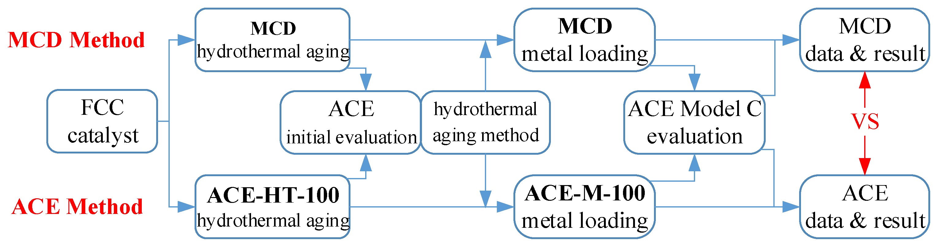
2.2. Metal Contamination and Evaluation Scheme

The pretreatment steps and schemes for metal contamination for the MCD method and ACE method are shown in Figure 2. Taking the MCD method as an example, the steps in the experimental and evaluation method are as follows:
(1)
The fresh catalyst is roasted first, then 100 g is weighed for each reactor.
(2)
A series of hydrothermal aging temperatures and times are set, along with the corresponding air flow, water volume, temperature, and other parameters.
(3)
A micro-catalytic performance evaluation and product cutting distillation analysis for the initial aging catalyst is conducted to determine the hydrothermal aging method.
(4)
Based on the determined hydrothermal aging method, the metal target value is set and the original oil with heavy metal raw material is configured through the corresponding calculation formula for the metal loading. After the experiment, the metal-contaminated catalysts are removed, weighed, and sealed for subsequent analysis and testing.
(5)
The amount of metal loading on the FCC catalysts is detected by X-Ray fluorescence analysis to determine whether the catalyst has reached the metal pollution target, and ACE Model C microcatalytic evaluation is carried out.
(6)
The pore volume, specific surface area, unit cell constant, and metal content on the catalyst are analyzed and the corresponding data on the metal-contaminated catalysts and equilibrium catalysts are compared.
During the operation of multi-channel cyclic metal loading in step (4), the catalytic cracking catalyst undergoes multiple cycles of reaction cracking, stripping, and high-temperature regeneration in a fixed bed reactor. In the reaction cracking stage, organic metal compounds are dissolved in the feed oil, then the feed oil is injected into the reactor through a feed pump to bring it into contact with the catalyst. The heavy metals are deposited on the surface of the catalyst. After the reaction is completed, high-purity nitrogen or water vapor is used for stripping to remove volatile hydrocarbons and the device is heated to the regeneration reaction temperature. In the regeneration reaction stage, an oxidizing gas mixed with water vapor is usually used as the treatment gas. The oxidizing gas can be mixed with high-purity nitrogen and oxygen or with high-purity nitrogen and sulfur dioxide. The simulation of complete and partial regeneration conditions can be achieved by adjusting the gas flow rate and gas composition during regeneration.

2.3. Experimental Conditions

In the catalyst preparation phase, the catalysts were first sieved using the ALPINE Air Jet Sieve e200LS (Osaka, Japan) to maintain the particle size distribution. Finally, catalyst particles ranging from 36 μm to 150 μm were obtained. After roasting at 600 °C for 2 h in a muffle furnace, they were placed in a dryer for later use. Due to the large amount of catalyst used in this experiment, it was necessary to screen and calcine all the catalysts at once, then dry and store them uniformly to ensure the uniformity of the catalyst.
(1)
The fresh FCC catalysts came from commercial samples numbered LDO-70 and LB-5, with a particle size between 36–150 μm, and were produced by the catalyst factory of Lanzhou Petrochemical Company (Lanzhou, China). The two commercial samples were mixed in a certain proportion, then weighed and subjected to subsequent hydrothermal aging and metal loading aging experiments as fresh catalysts for metal contamination. The mixture was mainly used to regulate the olefin yield; the two mixtures were used to reduce the error due to heavy metal loading on single catalyst samples. The fresh catalyst information is listed in Table 1.
(2)
Initial conditions for hydrothermal aging adopted the 90–95% water vapor values recommended by KBC Petro-sim. For the raw oil, we used a mixed oil provided by Kayser Technology Inc. Company (MI, USA) with a metal content of 3% for nickel and 1.64% for vanadium. The metal loading reaction temperature was 600 °C, the regeneration temperature was 600 °C, and the freezer temperature was 4.0 °C. In addition, the ratio of catalyst to oil was determined according to the target metal amount.
(3)
The crude oil used for microcatalytic evaluation was the raw material for a 3 million tons/year catalytic cracking unit. The performance parameters for the crude oil were 374 g/mol of molecular weight, 12.27 mm2/s of viscosity (100 °C), 867.3 kg/m3 of density (70 °C), and 4.17 wt% of residual carbon. The reaction temperature was 530 °C, with a catalyst–oil ratio of 5.0, while the regeneration temperature was 715 °C and the freezer temperature was −15.0 °C.

3. Results and Discussion

3.1. Comparison of Modified Conditions for Two Methods

After the completion of hydrothermal accelerated aging of the catalyst, its microactivity parameters need to be measured to determine its hydrothermal stability. According to this result, the aging conditions can be adjusted appropriately to bring the obtained aging catalyst performance closer to that of industrial equilibrium agents. First, by studying the aging conditions of key hydrothermal aging temperatures, an adjustment strategy for aging temperature and time is obtained; then, other hydrothermal aging conditions are adjusted to obtain a series of aging samples for microreaction analysis and fine tune the aging method based on the results at all levels. By combining the testing and adjustment of heavy metal pollution methods, the aging conditions of MCD and ACE methods were ultimately obtained.
By comparison with the reference conditions and conversion, the modified conditions for the MCD and ACE methods are listed in Table 2. The reference conditions from Petro-sim of KBC Corporation [13] was the evaluation basis for the commercial FCC catalyst, and the modified conditions were used to check and select the appropriate operating parameters. For the same fresh catalyst sample, the hydrothermal aging condition of ACE method is more severe than that of MCD method; however, the effect of metal contamination is the opposite.

3.2. Comparison of Heavy Metal Loading Efficiency

3.2.1. MCD Method

According to the FCC catalyst database, the average annual metal amount for the chosen equilibrium catalyst is 4429 ppm of Ni and 7137 ppm of V. Thus, the MCD device was set with the target metal levels of 4000 ppm Ni and 7000 ppm V, and the configuration of feedstock oil and heavy metal were matched. Then, the metal loading scheme was improved in order to obtain ideal metal contamination results for 1#Cat and the optimized loading scheme was tested on another sample of 1#Cat. The metal contamination results are listed in Table 3. As can be seen from Table 3, the metal content removed by the default setup was only half of the target value. After reconfiguring the feedstock oil metal content and enhancing the times of the new reaction unit cycles, the metal content was closer to the target value. Through an analysis of the measurement results, it can be seen that a suitable MCD method for metal contamination was established after optimization of the reaction conditions and parameters.

3.2.2. ACE Method

For the ACE method adopted the ACE M-100 device to carry out the metal loading test with target metal contents of 4400 ppm Ni and 7100 ppm V; the configuration and results are presented in Table 4. The parallel test used the same amount of catalyst and metal in the base oil with a different ratio of catalyst to oil and injection time in order to maintain the same loading results. The parallel tests all showed high metalated catalyst recovery of above 99.5%, and the metal content on catalyst was even slightly higher than the target value, which demonstrates excellent metal loading efficiency. Although the MCD device was able to achieve integrated hydrothermal and metal aging, there was a certain deviation between the total metal loading amount and the target value. The ACE device has an excellent material balance recovery rate, which ensured the accuracy of the experiment, and was able to achieve the metal contamination targets. Compared with the results of the MCD method, the ACE device has a significant advantage in the ability to set a lower target value for metal loading; however, the hydrothermal conditions of the ACE device aging method are more stringent.

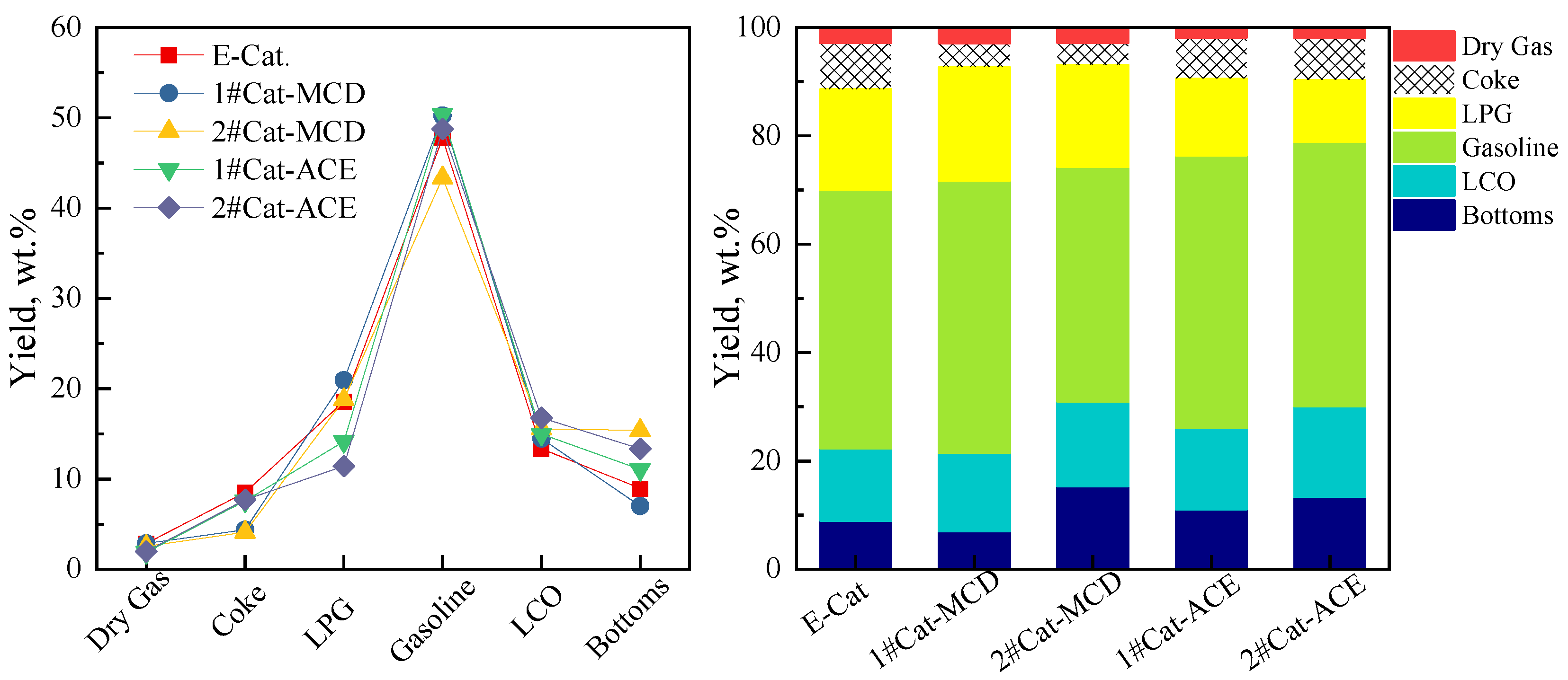
3.3. Microcatalytic Performance of Metal-Contaminated Catalysts

An equilibrium catalyst (E-Cat) with a high level of iron contamination was collected from WEPEC, the industrial plant of the Dalian West Pacific Petrochemical Co., Ltd. (Dalian, China). The microcatalytic performance of the metal-contaminated catalysts are presented in Figure 3, and the detail product distribution of dry gas, coke, liquefied petroleum gas (LPG), gasoline, and diesel (light cycle oil, LCO) are listed in Table 5. In comparison with the equilibrium catalyst (E-Cat.), 1#Cat for the MCD and ACE methods has similar conversion to the E-Cat, while the deactivation is more severe for 2#Cat. When using the MCD method, the metal-contaminated catalysts have less coke, gasoline, and bottoms than when using E-Cat and ACE. This demonstrates that the catalysts are less deactivated due to the lower metal contamination. Although its metal loading accuracy and parallel efficiency are similar even through multiple cycles and simulations of industrial devices, the simulated metal-contaminated catalyst of ACE still has difference from the industrial E-Cat. Therefore, the catalytic performance is somewhat different with E-Cat. Moreover, the catalyst performance for the ACE method has similar hydrogen and coke yields to those of E-Cat, which proves the advantage of metal loading for the ACE method.

4. Conclusions

Two pretreatment methods of metal loading on FCC catalysts are presented in laboratory simulations of metal contamination on industrial equilibrium catalysts. The pretreatment schemes are tested and proven to be applicable for the analysis of heavy metal loading mechanisms.
(1)
With the help of modern devices, the typical operating parameters for hydrothermal aging and metal loading can be adjusted to suit different metal types and content targets in both the MCD and ACE methods. These two simulation methods can obtain extremely high data accuracy for metal contamination while ensuring the parallel reliability, repeatability, and reproducibility of experimental results.
(2)
The MCD method has advantages in the basic hydrothermal aging treatment, although the high level of metal loading is slightly less than the target value, which leads to lower deactivation and hydrogen yield. Enhancing the metal ratio in the feed oil or the timing of the reactor cycles could improve the metal loading efficiency.
(3)
The ACE method has significant advantages for metal contamination thanks to precise loading amounts and excellent metal loading efficiency. In addition, the simulated metal-contaminated catalyst has similar activation to that of industrial equilibrium catalysts. The pretreatment scheme can be used for commercial evaluation for new catalysts, and allows fundamental experiments for metal contamination and its improvement for FCC catalysts.

Author Contributions

Conceptualization, Y.Y. and Z.Z.; methodology, Y.Y.; investigation and validation, C.L. and Y.S.; formal analysis, X.M. and H.L.; data curation, Z.Z.; writing—original draft preparation, Y.Y.; writing—review and editing, H.L.; project administration and funding acquisition, D.J. All authors have read and agreed to the published version of the manuscript.

Funding

This research was funded by the Key R&D program of Gansu Province (No. 20YF8GD139).

Institutional Review Board Statement

Not applicable.

Informed Consent Statement

Not applicable.

Data Availability Statement

The data presented in this study are available on request from the first author.

Acknowledgments

The experimental method and operation were supported by the Lanzhou Petrochemical Research Center.

Conflicts of Interest

The authors declare no conflict of interest.

References

  1. Ma, Y.; Liao, Y.; Su, Y.; Ji, D.; Li, H.; Yang, Y. A Novel Method to Investigate the Activity Tests of Fresh FCC Catalysts: An Experimental and Prediction Process from Lab Scale to Commercial Scale. Processes 2021, 9, 209. [Google Scholar] [CrossRef]
  2. Che, Y.; Yuan, M.; Qiao, Y.; Liu, Q.; Zhang, J.; Tian, Y. Fundamental study of hierarchical millisecond gas-phase catalytic cracking process for enhancing the production of light olefins from vacuum residue. Fuel 2019, 237, 1–9. [Google Scholar] [CrossRef]
  3. Stepanov, N.D.; Shaysultanov, D.G.; Salishchev, G.A.; Tikhonovsky, M.A.; Oleynik, E.E.; Tortika, A.S.; Senkov, O.N. Effect of V content on microstructure and mechanical properties of the CoCrFeMnNiVx high entropy alloys. J. Alloys Compd. 2015, 628, 170–185. [Google Scholar] [CrossRef]
  4. Souza, N.L.A.; Tkach, I.; Morgado, E., Jr.; Krambrock, K. Vanadium poisoning of FCC catalysts: A quantitative analysis of impregnated and real equilibrium catalysts. Appl. Catal. A Gen. 2018, 560, 206–214. [Google Scholar] [CrossRef]
  5. Tangstad, E.; Andersen, A.; Myhrvold, E.M.; Myrstad, T. Catalytic behaviour of nickel and iron metal contaminants of an FCC catalyst after oxidative and reductive thermal treatments. Appl. Catal. A Gen. 2008, 346, 194–199. [Google Scholar] [CrossRef]
  6. Zhang, C.C.; Gao, X.; Yilmaz, B. Development of FTIR Spectroscopy Methodology for Characterization of Boron Species in FCC Catalysts. Catalysts 2020, 10, 1327. [Google Scholar] [CrossRef]
  7. Liu, Z.; Zhang, Z.; Liu, P.; Zhai, J.; Yang, C. Iron contamination mechanism and reaction performance research on FCC catalyst. J. Nanotechnol. 2015, 2015, 273859. [Google Scholar] [CrossRef] [Green Version]
  8. Liao, Y.; Liu, T.; Du, X.; Gao, X. Distribution of Iron on FCC Catalyst and Its Effect on Catalyst Performance. Front. Chem. 2021, 9, 640413. [Google Scholar] [CrossRef] [PubMed]
  9. Whitcombe, J.M.; Agranovski, I.E.; Braddock, R.D. Identification of Metal Contaminants on FCC Catalyst. Part. Part. Syst. Charact. 2005, 22, 268–275. [Google Scholar] [CrossRef]
  10. Tian, H.; Huang, C.; Fan, Z. Metals on a novel USY zeolite after hydrothermal aging. Stud. Surf. Sci. Catal. 2001, 139, S0167–S2991. [Google Scholar]
  11. Bai, P.; Etim, U.J.; Yan, Z.; Mintova, S.; Zhang, Z.; Zhong, Z.; Gao, X. Fluid catalytic cracking technology: Current status and recent discoveries on catalyst contamination. Catal. Rev. 2018, 61, 333–405. [Google Scholar] [CrossRef]
  12. Musavuli, K.C.; Engelbrecht, N.; Everson, R.C.; Grobler, G.L.; Bessarabov, D. CO Preferential Oxidation in a Microchannel Reactor Using a Ru-Cs/Al2O3 Catalyst: Experimentation and CFD Modelling. Processes 2021, 9, 867. [Google Scholar] [CrossRef]
  13. Liao, Y.; Liu, T.; Zhao, H.; Gao, X. A Comparison of Laboratory Simulation Methods of Iron Contamination for FCC Catalysts. Catalysts 2021, 11, 104. [Google Scholar] [CrossRef]
  14. Buurmans, I.L.; Soulimani, F.; Ruiz-Martínez, J.; van der Bij, H.E.; Weckhuysen, B.M. Structure and acidity of individual fluid catalytic cracking catalyst particles studied by synchrotron-based infrared micro-spectroscopy. Microporous Mesoporous Mater. 2013, 166, 86–92. [Google Scholar] [CrossRef]
  15. Etim, U.J.; Bai, P.; Liu, X.; Subhan, F.; Ullah, R.; Yan, Z. Vanadium and nickel deposition on FCC catalyst: Influence of residual catalyst acidity on catalytic products. Microporous Mesoporous Mater. 2019, 273, 276–285. [Google Scholar] [CrossRef]
  16. Nguyen, T.H.; Ngo, P.T.; Tran, T.V.; Nguyen, S.; Vu, D.M.; Ha, Q.L.M.; Dao, X.T.T.; Dang, T.T. Effect of hydrothermal conditions on the catalytic deactivation of a fluid cracking catalyst. React. Kinet. Mech. Catal. 2013, 109, 563–574. [Google Scholar] [CrossRef]
  17. Chiranjeevi, T.; Gokak, D.; Ravikumar, V.; Viswanathan, P. Development of New Deactivation Method for Simulation of Fluid Catalytic Cracking Equilibrium Catalyst. J. Chem. Sci. 2014, 126, 353–360. [Google Scholar] [CrossRef]
  18. Wallenstein, D.; Harding, R.; Nee, J.; Boock, L. Recent Advances in the Deactivation of FCC Catalysts by Cyclic Propylene Steaming (CPS) in the Presence and Absence of Contaminant Metals. Appl. Catal. A Gen. 2000, 204, 89–106. [Google Scholar] [CrossRef]
  19. Gerritsen, L.; Wijngaards, H.; Verwoert, J.; O’Connor, P. Cyclic Deactivation: A Novel Technique to Simulate the Deactivation of FCC Catalyst in Commercial Units. Catal. Today 1991, 11, 61–72. [Google Scholar] [CrossRef]
  20. Lerner, B.; Deeba, M. Improved Methods for Testing and Assessing Deactivation from Vanadium Interaction with Fluid Catalytic Cracking Catalyst. In Deactivation and Testing of Hydrocarbon-Processing Catalyst; O’Connor, P., Takatsuka, T., Woolery, G.L., Eds.; ACS Symposium Series; American Chemical Society: Washington, DC, USA, 1996; Volume 634, pp. 296–311. [Google Scholar]
  21. Wallenstein, D.; Farmer, D.; Knoell, J.; Fougret, C.; Brandt, S. Progress in the Deactivation of Metals Contaminated FCC Catalysts by a Novel Catalyst Metallation Method. Appl. Catal. A Gen. 2013, 462, 91–99. [Google Scholar] [CrossRef]
Figure 1. Main experimental device used for the pretreatment of metal loading on FCC catalysts.
Processes 11 02014 g001
Figure 2. Pretreatment method and evaluation scheme for metal contamination on FCC catalyst and evaluation scheme.
Processes 11 02014 g002
Figure 3. Product distribution of metal-contaminated catalysts.
Processes 11 02014 g003
Table 1. Fresh catalysts used for metal contamination.
No.ProportionPotential Device
1#CatLDO-70: LB-5 = 6:13 million—Base
2#CatLDO-70: LB-5 = 4.25:13 million—New
Table 2. MCD and ACE conditions for hydrothermal aging and heavy metal contamination.
No.DescriptionRef. Steaming Cond.Ref. Conv.
%
MCD MethodACE Method
TempHoursPressSteamTempHoursTempHours
1Fresh7056195%76.747251873524
2Mild7606195%71.857801879024
3Moderate Base7756195%69.137951880524
7Moderate + Metals7756195%68.44 *4000 ppm Ni
7000 ppm V
5000 ppm Ni
3000 ppm V
8Severe7956195%67.18051881524
Note: * The reference conversion of 68.44 wt% was given on the case of 3000 ppmw Ni and 3000 ppmw V.
Table 3. Heavy metal contamination using the MCD method.
Loading SchemeMetal Contamination Results for 1#Cat
Ni/ppmRSD (%)V/ppmRSD (%)
Target value4000-7000-
Default setup22000.5635000.44
Enhance metal ratio in feed oil25000.4740000.39
Enhance times of reactor cycles34000.2763000.22
Metal contamination results for 2#Cat
Enhance times of reactor cycles39000.3163000.25
Table 4. Heavy metal contamination with ACE method, showing the parallel accuracy.
Catalyst No.1#Cat-11#Cat-21#Cat-3
Mass of FeedCatalyst Load, gms100.0100.0100.2
Ni Oil, gms1.8811.8711.871
V Oil, gms5.5215.5035.503
Base Oil, gms3.2674.6964.696
Cat-to-Oil Ratio, wt/wt9.378.288.30
Injection TimePre-Feed Oil, secs408080
Ni Oil, secs858888
V Oil, secs250254254
Base Oil, secs120150150
Cat. Stripping, secs180300300
Calculated Metals on CatalystNi, ppmw451544924483
V, ppmw724372207206
Metallated Catalyst ProductExpected, gms101.75101.75101.95
Measured, gms101.30101.20101.40
Recovery, wt %99.699.599.5
Table 5. Microcatalytic performance for the metal-contaminated catalysts.
DescriptionE-Cat1#Cat-MCD2#Cat-MCD1#Cat-ACE2#Cat-ACE
Cracking Temp., °C515515515515515
Cat.-to-Oil, wt/wt55555
Yields, wt%:
Dry Gas2.872.862.551.871.99
LPG18.5820.9318.7914.1511.42
Gasoline47.7350.2443.3550.3848.75
LCO13.3414.4815.5514.9716.77
Bottoms8.96715.3711.0613.35
Coke8.524.374.127.577.71
Recovery, wt%100.199.8799.72100100
Conv., wt%77.778.468.8173.9769.87
total liquid yield, wt%79.6585.6477.6979.576.95
Light yield, wt%61.0864.7158.965.3565.52
Selectivity, wt%:
Dry Gas/Conv.0.0370.0360.0370.0250.028
LPG/Conv.0.2390.2670.2730.1910.163
Gasoline/Conv.0.6140.6410.6300.6810.698
Coke/Conv.0.1100.0560.0600.1020.110
Gas Yields, wt%
Hydrogen0.540.170.090.450.59
Hydrogen Sulfide0.010.010.0100
Methane1.121.2510.620.64
Ethane0.650.630.710.40.4
Ethylene0.550.80.740.40.37
Propane1.732.061.440.610.49
Propylene5.695.825.494.253.5
n-Butane0.841.251.070.570.4
Isobutane5.697.136.062.691.74
1-Butene1.661.180.981.221.05
Isobutylene2.041.521.491.821.79
c-2-Butene1.260.811.031.271.04
t-2-Butene1.351.151.241.691.38
Disclaimer/Publisher’s Note: The statements, opinions and data contained in all publications are solely those of the individual author(s) and contributor(s) and not of MDPI and/or the editor(s). MDPI and/or the editor(s) disclaim responsibility for any injury to people or property resulting from any ideas, methods, instructions or products referred to in the content.

